Production and Detection of Axion-Like Particles in a HERA Dipole Magnet
– Letter-of-Intent for the ALPS experiment –
Abstract
Recently, the PVLAS collaboration has reported evidence for an anomalous rotation of the polarization of light in vacuum in the presence of a transverse magnetic field. This may be explained through the production of a new light spin-zero (axion-like) neutral particle coupled to two photons. In this letter-of-intent, we propose to test this hypothesis by setting up a photon regeneration experiment which exploits the photon beam of a high-power infrared laser, sent along the transverse magnetic field of a superconducting HERA dipole magnet. The proposed111The experiment has been approved by the DESY directorate on January 11, 2007. ALPS (Axion-Like Particle Search) experiment offers a window of opportunity for a rapid firm establishment or exclusion of the axion-like particle interpretation of the anomaly published by PVALS. It will also allow for the measurement of mass, parity, and coupling strength of this particle.
I Introduction and Motivation
New very light spin-zero particles are predicted in many models beyond the Standard Model. Often they would couple only very weakly to ordinary matter. Typically, such light particles arise if there is a global continuous symmetry in the theory that is spontaneously broken in the vacuum — a notable example being the axion Weinberg:1978ma , a pseudo scalar particle arising from the breaking of a U(1) Peccei-Quinn symmetry Peccei:1977hh , introduced to explain the absence of violation in strong interactions. Such axion-like pseudo scalars couple to two photons via
| (1) |
where is the coupling, is the field corresponding to the particle, () is the (dual) electromagnetic field strength tensor, and and are the electric and magnetic fields, respectively.

In the case of a scalar particle coupling to two photons, the interaction reads
| (2) |
Both effective interactions give rise to similar observable effects. In particular, in the presence of an external magnetic field, a photon of frequency may oscillate into a light spin-zero particle of small mass , and vice versa. The notable difference between a pseudo scalar and a scalar is that it is the component of the photon polarization parallel to the magnetic field that interacts in the former case, whereas it is the perpendicular component in the latter case.
The exploitation of this mechanism is the basic idea behind photon regeneration (sometimes called “light shining through walls”) experiments regeneration ; VanBibber:1987rq , see Fig. 1. Namely, if a beam of photons is shone across a magnetic field, a fraction of these photons will turn into (pseudo-)scalars. This (pseudo-)scalar beam could then propagate freely through a wall or another obstruction without being absorbed, and finally another magnetic field located on the other side of the wall could transform some of these (pseudo-)scalars into photons — apparently regenerating these photons out of nothing. A pilot experiment of this type was carried out in Brookhaven using two prototype magnets for the Colliding Beam Accelerator Ruoso:1992nx . From the non-observation of photon regeneration, the Brookhaven-Fermilab-Rochester-Trieste (BFRT) collaboration excluded values of the coupling , for eV Cameron:1993mr (cf. Fig. 2), at the 95 % confidence level.
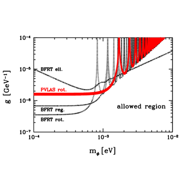
Top panel: The 95 % confidence level upper limits from BFRT data Cameron:1993mr on polarization (rotation and ellipticity data) and photon regeneration are displayed as dotted lines.. The preferred values corresponding to the anomalous rotation signal observed by PVLAS Zavattini:2005tm are shown as a thick solid line.
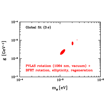
Bottom panel: Three sigma allowed region from PVLAS data on rotation plus BFRT data on rotation, ellipticity, and regeneration Ahlers:priv .
Recently, the PVLAS collaboration has reported an anomalous signal in measurements of the rotation of the polarization plane of a laser beam in a magnetic field Zavattini:2005tm . A possible explanation of such an apparent vacuum magnetic dichroism is through the production of a light pseudo scalar or scalar, coupled to photons through Eq. (1) or Eq. (2), respectively. Accordingly, photons polarized parallel (pseudo scalar) or perpendicular (scalar) to the magnetic field disappear, leading to a rotation of the polarization plane Maiani:1986md . The region quoted in Ref. Zavattini:2005tm that might explain the observed signal is around (95 % confidence level)
| (3) | |||||
| (4) |
obtained from a combination of previous limits on vs. from a similar, but less sensitive polarization experiment performed by the BFRT collaboration Cameron:1993mr and the vs. curve corresponding to the PVLAS signal (cf. Fig. 2 (lower panel) where also two other small allowed (at 3 sigma) regions are displayed.).
A particle with these properties presents a theoretical challenge. It is hardly compatible with a genuine QCD axion Raffelt:2005mt ; Ringwald:2005gf . Moreover, it must have very peculiar properties in order to evade the strong constraints on from stellar energy loss considerations Raffelt:1985nk and from its non-observation in the CERN Axion Solar Telescope Andriamonje:2004hi ; Raffelt:2005mt . Its production in stars may be hindered, for example, if the vertex is suppressed at keV energies due to low scale compositeness of , or if, in stellar interiors, acquires an effective mass larger than the typical photon energy, keV, or if the particles are trapped within stars Masso:2005ym ; Jain:2005nh ; Jaeckel:2006id ; Mohapatra:2006pv .
Clearly, an independent and decisive experimental test of the particle interpretation of the PVLAS observation, without reference to axion production in stars (see Dupays:2005xs ; Kleban:2005rj ; Fairbairn:2006hv ), is urgently needed Ahlers:2006iz . In Ref. Ringwald:2003ns , one of us (AR) proposed to exploit the strong magnetic field of superconducting HERA dipole magnets for a photon regeneration experiment. In this letter-of-intent, we propose a possible realization of such an experiment.
Within the international community the PVLAS results have triggered substantial activities. Besides this proposal efforts are under way in Europe (at CERN, INFN and within a collaboration of different laboratories in France) and the US (at Jefferson Laboratories) to directly test the particle interpretation of the PVLAS result (for a review see Ringwald:2006rf ). Recently a corresponding workshop took place at the Institute for Advanced Studies workshop in Princeton. According to the presented time schedules ALPS could be the first experiment to clarify experimentally whether a previously unknown particle can be created by interactions of photons with a strong magnetic field.
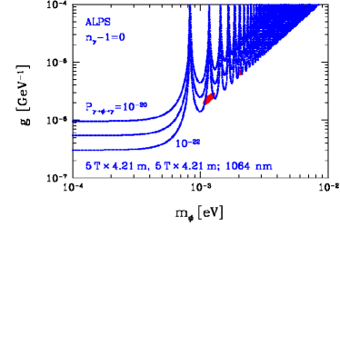
Top panel: Iso-contours of the regeneration probability probability , Eq. (5), for the parameters of the HERA dipole magnet, T, m, exploiting an infrared photon beam, nm, corresponding to eV, in vacuum ().
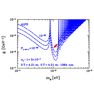
Bottom panel: Same as top panel, but in buffer gas with .
II Photon regeneration in a HERA dipole magnet
We start with a discussion of the probability that an initial photon with energy converts, in the magnetic field region of size and length in front of the wall, into an axion-like particle, and reconverts, in the magnetic field region of size and length on the other side of the wall, into a photon. It is given by
| (5) |
where is the probability that a photon converts into an axion-like particle,
| (6) |
Here,
| (7) |
is the momentum transfer to the magnetic field, i.e. the modulus of the momentum difference between the photon and the axion-like particle, and
| (8) |
is a form factor which reduces to unity for small momentum transfer . For large , incoherence effects emerge between the (pseudo-)scalar and the photon, the form factor getting much smaller than unity, severely reducing the conversion probability. Clearly, in vacuum, the photon mass vanishes, . In a refractive medium, which may be realized in our experiment by filling in buffer gas vanBibber:1988ge , the effective mass is given by
| (9) |
where is the refraction index of the medium. Therefore, by tuning , i.e. by varying the gas pressure in the magnetic field regions, one may optimize the sensitivity in certain mass regions by essentially tuning toward small values.
In Fig. 3, we display iso-contours of the regeneration probability in the ––plane, for the parameters of the HERA dipole magnet, T, m, exploiting an infrared photon beam, nm, corresponding to eV, in vacuum (; top panel) and with buffer gas (; bottom panel). We infer from that figure that it will be very important to have the possibility to run the experiment with a buffer gas of an optimal refraction index. In order to probe the PVLAS preferred region, the other experimental parameters, such as the laser power, eventual pulsing, and detector performance have to be designed in such a way as to be able to test a photon regeneration probability in the range (cf. Fig. 3 (bottom panel)).
III Experimental Realization
We propose a photon-regeneration experiment planned around a spare dipole of the HERA proton storage ring at the DESY magnet test stand. Both parts of the experiment, i.e. axion-like particle production and photon-reconversion have to be accommodated in one single magnet since the test stand architecture in its present configuration forbids to place two fully functional magnets in line.
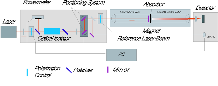
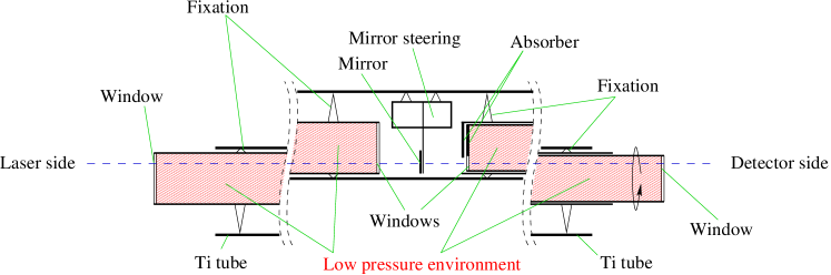
The general layout of the experiment is depicted in Fig. 4. A high intensity laser beam is placed on one side of the magnet traversing half of its length. In the middle of the magnet, the laser beam is reflected back to its entering side, and an optical barrier prevents any photons from reaching the second half of the magnet. Axion-like particles would penetrate the barrier, eventually reconverting into photons inside the second half of the magnet. Reconverted photons are then detected with a pixeled semi-conductor detector outside the magnet. The individual components of the experiment are discussed in the following.
III.1 Magnet
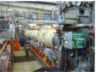
The magnetic field will be produced by a spare dipole magnet of the HERA proton storage ring. At a nominal current of 6000 A, the magnet reaches a field of 5.355 T over a total magnetic length of 8.82 m. The device is in place at the magnet test stand in building 55 (Fig. 5).
The length of the magnet including one compensating end flange is 9766 mm. The “open” magnet is connected at both ends to two Helium feed boxes of 1180 mm diameter. These boxes are the interfaces to the vacuum, to the cold Helium and to the electric current for the magnet.
The cold inner beam pipe of the magnet has a temperature of 4 K and is bent with a radius of approx. 588 m to follow the HERA curvature. A “warm” instrumentation tube of Titanium is inserted into the magnet to allow for instrumentation for magnetic field measurements. This tube has an overall length of 13.5 m, follows the curvature of the beam pipe and acts also as a vacuum barrier to the surrounding atmosphere. The instrumentation tube is insulated against the cold beam pipe by super insulation. During magnet tests, the tube is flushed with warm Nitrogen to keep it at room temperature. As a side effect the heat load on the magnet is high. About 30 g/s of 4 K Helium are needed to keep the magnet cold and to prevent quenches at 6000 A.
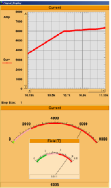
After a long shutdown the magnet was successfully put into operation again on September 26, 2006. A screen shot of the control monitor is shown in Fig. 6.
The position of the Titanium tube was measured by the DESY geometers. Although it follows the curvature of the beam pipe, an open aperture of approximately 18 mm is available around a straight line-of-sight along the whole length, placing geometrical constraints on the following considerations for the ALPS experiment.
III.2 Magnet Insert Unit
The Magnet Insert Unit (MIU) covers all instrumentation inside the magnet. It will be inserted into the Titanium tube already installed inside the magnet. Following the procedure of standard magnet tests, this tube will be flushed with dry nitrogen of around 300 K temperature while the magnet is cooled to liquid helium temperatures.
The main purpose of the MIU is to provide a suitable low pressure environment (LPE) which the laser beam passes on its way toward the mirror and back. It needs to meet several requirements:
-
1.
The space between the MIU and the measuring pipe must allow for a nitrogen flow large enough: to keep the temperature of the inner measurement-pipe wall everywhere a few degrees above room temperature and to remove the heat produced in the reflecting mirror.
-
2.
The pressure of the gas species inside the MIU is to be varied between 1 bar and 10 mbar. In order to minimize contamination, the pipe has to be evacuated and possibly baked out before introducing the gas. If, at lower working pressures, degassing from the interior of the insert ceases to be negligible, continuous pumping and replenishing the gas will be required. In that case, in order to minimize pressure deviations along the length of the magnet, a large diameter of the tube is desirable. Also, the gas may be admitted through a long capillary with several holes along its length.
-
3.
The gas pressures in front of and behind the mirror need to be equal. A convenient way to achieve this is to connect both parts by a bypass line. Since absolutely no light from the laser may propagate into the tube part with the detector, the connection must contain a highly effective light trap. To make the connection symmetrical with respect of flow conductance and to separate gas inlet and vacuum outlet, two pairs of light traps are needed. If the two parts cannot be connected the pressures in both parts need to be measured and controlled separately to make them equal. This method is experimentally more demanding, but does not require light traps.
In designing the MIU, a compromise between two diverging objectives has to be found: reliable, repeatable and easy alignment of the axis of the laser beam and the photon detector and complete optical separation of the laser and the detector part, so that none of photons produced on the laser side reaches the detector.
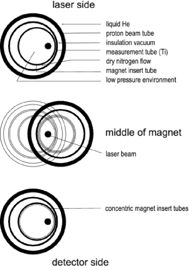
We propose to start with an MIU shown in Figs. 7 and 8 consisting of three parts:
-
1.
The laser side part, consisting of a metal tube of 7 m length, approx. 35 mm outer diameter and 1 mm wall thickness, with an optical window at each end. It is inserted from the laser side.
-
2.
A dielectric mirror that reflects the laser beam. It is mounted on a holder such that it can be electro mechanically tilted around two axes which are perpendicular to each other and located in the mirror plane. It is inserted into the measurement pipe either by a special tool or in connection with the laser part. The temperature of the mirror is measured with a temperature sensor. The laser beam is reflected back out of the magnet, separated by the optical insulator and directed into a laser beam dump.
-
3.
The detector side part consists of two concentric metal tubes of 1 mm wall thickness each. The outer tube has an outer diameter of approx. 37 mm. It is inserted from the detector side. The inner tube is terminated with a full window at the detector end. At the end pointing to the laser there is a smaller, eccentric window and, diametrically across it, a light trap. The inner tube may be rotated between one position where the axis of the laser beam passes the two windows, and another, where the laser beam axis is blocked by the light trap.
Both tube subunits are suspended by (asymmetric) distance holders (fixed to the tubes) which glide on the inner wall of the measuring pipe when the MIU is being inserted. That way, in the middle of the magnet, they touch the inside wall of the measuring pipe on the side with the smaller bending radius and on the opposite side (with the larger bending radius) at the ends of the magnet. The mirror surface is optically usable approx. 1 mm from its edge. This leaves a horizontal clearance of 14 mm for the laser beam into and out of the tube subunits. The parts outside the magnet of the laser side tube and of the inner detector side tube are equipped with vacuum tight connectors for pumping, gas inlet and electrical wiring. The space between the MIU and the measuring pipe is subjected to a dry nitrogen flow.
The tube material (e.g. aluminum, stainless steel, OHFC copper, Titan) will be selected later in the design process.
An alternative MIU design which concentrates on assuring a complete optical separation between laser and detector part, has also been considered and is only summarized here:
-
•
The reflecting mirror is placed inside the laser side tube. Behind the mirror the tube is closed by a metal plate so that no light can escape.
-
•
On the detector side there is just one closed tube with a window on the outer end.
-
•
Both tubes are joined in the middle of the magnet by a sliding coupling.
With this alternative MIU the optical adjustment requires a complex procedure. It relies entirely on the permanent correspondence between the position and direction of the laser beam axis and reference beams derived from it (cf. Fig. 4). Both the detector and the laser assembly need to be moved in and out of the magnet beam path in a reproducible way.
In spite of its drawbacks, this second MIU design can serve as a fall-back solution in case of unsurmountable difficulties with the preferred design as well as a cross checking option in case of evidence for axion-like particles. In setting up the experiment, we intend to make the necessary preparations to be able to implement and use this MIU design if needed.
III.3 Laser
| Laser Concept | Output Power (W) | Beam Quality () | Polarization | Operation |
|---|---|---|---|---|
| Rod-Laser | 100 - 4.000 | 35 - 75 | random | cw |
| Disk-Laser | 250 - 8.000 | 12 - 24 | random / linear | cw |
| Fiber-Laser | 100 - 10.000 | 1.15 - 35 | random / linear | cw, qcw |
The design of the laser system is driven by two main aspects: the need of large intensity of order photons/s and the small aperture of the MIU. In addition, controllable linear polarization is desirable to distinguish scalar and pseudo scalar axion-like particles and to allow for systematic tests. Commercial laser systems with the required intensity are available for near-infrared wavelengths of order 1100 nm. Typical parameters for different technologies are listed in Tab. 1.
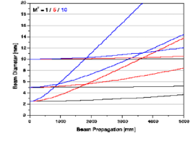
An important characteristics is the beam quality factor given by
| (10) |
which depends on the initial beam radius , the divergence angle and the wavelength . In the proposed setup, the laser beam diameter is at best equal at the entrance and exit of the magnet, and due to finite divergence hence has to be minimal on the mirror in the middle of the magnet. Fig. 9 shows the evolution of beam diameters with the propagation length for different values and initial diameters. It is evident that beam qualities with are needed to safely guide the laser through the magnet.
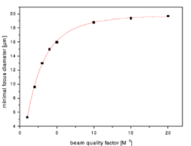
It is planned to focus the reconverted photons on a small region of the detector to allow the use of small pixeled semiconductors with low noise. The path of incoming laser photons, created axion-like particles and reconverted photons lay on top of each other for all practical purposes, and so the initial laser beam quality also determines the minimal spot size of reconverted photons reachable on the detector. A corresponding curve is shown in Fig. 10. The required beam quality can be easily achieved.
In summary: Commercial available laser systems in the near-infrared region with output power above 200 W (corresponds to a flux exceeding photons per second) and high beam quality match the requirements of the ALPS proposal. However such systems are only available operating in cw-mode.
III.4 Detector
Considering the conversion probability (Fig. 3) and the laser properties discussed above we expect a signal of the order of 10 photons/s, equivalent to W. The detector must be able to detect photons at this low rate. Although this is challenging, comparable sensitivities are reached in detectors for infrared astronomy.
In the following we will concentrate on semiconductor detectors. As the ALPS time schedule is somewhat ambitious we prefer commercial available systems and can not afford for time consuming extensive R&D.
Silicon, InGaAs, and HgCdTe have been considered up to now. For these materials sensors from single diodes up to two-dimensional cameras are available.
-
•
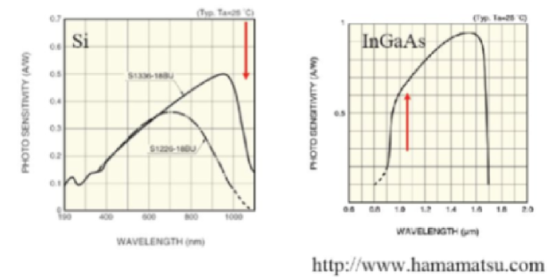
Silicon:
Silicon detectors normally reach their highest efficiency at wavelengths around 700 nm. At 1070 nm the quantum efficiencies reach typically only very few percent. Therefore silicon detectors seem to be inadequate to our requirements. -
•
InGaAs:
InGaAs detectors are frequently used in infrared astronomy. Usually they are sensitive to photon wavelengths above 800 nm and up to 1700 nm (or 2,500 nm in extended versions). -
•
HgCdTe:
Such detectors have also been used in infrared astronomy since quite some time. They offer a similar sensitivity range as InGaAs detectors.
Figure 11 shows typical sensitivities of Si and InGaAs diodes.
We have decided to focus on InGaAs in the following while still considering HgCdTe as a possible alternative.
InGaAs sensors are available as single diodes, one-dimensional and two-dimensional arrays. As the laser will be essentially operated in cw-mode we do not need fast triggering and gating. Therefore we principally prefer two-dimensional arrays:
-
•
They are less sensitive to potential misalignments.
-
•
The beam could be focused on the most sensitive pixel.
-
•
Pixels outside the signal region could be used to monitor the background conditions.
Semiconductor detectors suffer from dark current and read out noise. To reach the required sensitivity the total background has to be limited. As an exemplary calculation the maximal background is estimated requiring a five standard deviation detection of the signal assuming a measurement with signal and subtracting a background measurement .
| (11) |
Assuming and for an integration time of 10 minutes a background rate of about 1 kHz could be allowed for considering only statistics. In the experimental set-up it remains to be proven that the systematic uncertainties are sufficiently well under control.
The dark current is strongly influenced by the operation temperature. To minimize the technical efforts we will consider only cooling by Peltier modules (down to 180 K) or liquid nitrogen (77 K).
We would like to stress that in the near infrared region considered here the background induced by thermal radiation of the environment amounts to at most only few photons per minute (depending on the size of the detector) and hence is neglected.
In summary:
-
•
The detector should be based on InGaAs or HgCdTe.
-
•
Fast triggering and gating is not required.
-
•
The dark current should preferably be below 103 electrons per second.
-
•
The detector will be cooled by Peltier modules or liquid nitrogen.
-
•
A two-dimensional array is to be preferred with respect to a one dimensional array or single diodes.
-
•
Small area detector elements can be used due to the option to focus the laser beam. This will help to reduce the noise.
At DESY nearly no experience with low intensity infrared detection exists. In order to build up some competence the infrared sensitive camera ST-402 ME-C1 (Santa Barbara Instrument Group) has been ordered in summer. Although this Si-detector could not be used at ALPS it would be an easy-to-use device to gain some insight into eventual experimental difficulties. However due to the new EU regulations (RoHS) on lead-free soldering the camera has not arrived yet.
One of us (GW) has an InGaAs camera at hand (XEVA-USB-FPA-640). At present the properties of the camera are investigated, but probably the noise level does not match our requirements. Further tests including cooling are under way.
Therefore we do not have at present a detector available matching the requirement. Four directions could be followed to arrive at an adequate system:
-
•
Continue the tests with the camera at hand and check also other commercially available solutions (i.e. from Princeton Instruments).
-
•
Check the possibility to develop own read-out electronics (based on commercial available ASICS) for InGaAs CCD chips.
-
•
Develop a detector based on single diodes.
-
•
Check whether a system could be copied or even borrowed from an infrared astronomy group.
Significant effort is necessary within the next three month to develop a detector system. Dedicated personnel resources are necessary. However no show-stoppers have been identified yet so that confidence exists to reach the goals. It would be nice if at least two different systems could be built to allow for systematic studies at the experiment.
III.5 Alignment
The alignment procedure consists of five steps:
-
1.
The inner detector tube is rotated into the position where the laser beam passes the two windows of the inner detector side tube (see Fig. 8). The laser beam is directed toward the mirror and reflected back into the laser beam dump.
-
2.
The detector now is aligned w.r.t. the laser beam by using the fraction of laser radiation not being reflected or absorbed by the mirror (less than 1 %). During this step, the detector will be protected by additional laser attenuation outside the magnet and decoupled from the detector.
-
3.
A low intensity reference beam, generated from the main laser beam with a beam splitter, is centered onto a position sensor which is fixed with respect to the detector. From then on the position of the reference beam is continuously monitored using the position sensor. An auto alignment system will use this information to maintain a proper alignment of laser beam and detector.
-
4.
The inner detector side tube is now rotated into a position where the light trap is behind the mirror, so that any light originating from the laser and passing the mirror is blocked.
-
5.
The mirror system inside the magnet might have moved during tube rotations and now needs to be re-aligned in order to reflect the laser beam out of the magnet and into the beam dump again. Neither laser nor detector will be affected by this step, thus the alignment between these two units remains unchanged.
Optionally, the adjustment procedure can be repeated between measurement runs.
III.6 Safety
In the experiment we are confronted with the following hazards:
-
•
Cryogenic temperatures;
-
•
high magnetic fields;
-
•
high electric currents;
-
•
intense laser beam.
The experiment utilizes the magnet test stand in building 55. Safety concepts for the first three items are established for this area and will not be repeated here.
During normal operation the main laser beam will be constrained to the tube of the HERA magnet without having a chance to escape. Also any reference beam aside the magnet will be guided in closed tubes. A detailed safety report (“Gefahrenanalyse”) for the laser operation will be prepared once a specific laser system has been decided on.
Closed areas with fences and interlock doors will be established at both sides of the magnet. A simple electrical interlock loop will switch off the laser in case of risk like opening doors, quench of magnet, opening of the system etc.
IV Experimental Reach
In this section we estimate the sensitivity of the experiment w.r.t. the two physics goals: exploring the theoretical parameter space favored by the PVLAS results and reaching optimal exclusion limits in case of no signal observation.
The search for axion-like signals will be performed on data taken with and without the possibility of axion-like particle production, e.g. with the laser blocked before or guided through the magnet. Both measurements should be performed alternating to minimize any systematic effects. With equal integration time of the background and the signal-plus-background measurements, we will need a measuring time
in order to observe a 5 signal excess over background where and are the detected signal and background rates, respectively.
With the variable refraction index tunable with the gas pressure inside the LPE, we have the probability to adjust the maximum reconversion probability for each mass hypothesis, i.e. we can tune from equation 8 to be unity. The rate of reconverted photons then is completely determined by the parameters of the magnet and laser systems, with the coupling as sole free parameter. Assuming a laser with an output power of 200 W at 1070 nm sending its beam into a HERA dipole magnet we achieve
The coupling strength is given in ; is the efficiency of the detector and all optical components, which is not yet known exactly. Here we conservatively assume and with one achieves a signal . Hence with a background rate of 1 kHz it follows from the equation given above that are needed to observe a 5 signal. This time is to be doubled due to the necessity of a background measurement.
The allowed parameter space from the combination of PVLAS and BFRT is constrained to three regions with masses roughly between 1 and 3 meV and couplings above . In order to scan these mass ranges, we will need less than 100 different configurations for the LPE gas pressure, if the separation of the configurations is chosen such that the photon reconversion rate with one configuration is still 90 % at the mass for which the next configuration is optimal. The total measurement time to probe the parameter space allowed by the combination of the PVLAS and BFRT results thus is
To first approximation, the experimental reach for the axion mass is determined by the number of pressure configurations, while the sensitivity for the coupling depends on the integration time at each configuration. The reach in mass (coupling) depends on the square (on the fourth power) of the total measuring time, making it hard to explore phase space regions well beyond the PVLAS/BFRT allowed region.
To explore masses up to 5 meV would require 180 LPE configurations, while already 750
configurations are needed to reach 10 meV. Similarly, with an hour of
integration time per configuration, the coupling can be explored down to values of
GeV-1 with a possible improvement by one order of magnitude in the
more optimistic case of only 10 Hz background rate.
Based on these considerations, we are confident that the proposed ALPS experiment is sensitive enough to explore the parameter space for axion-like particle production allowed from the combination of PVLAS and BFRT. The potential to explore regions of the parameter space much further however are limited and can only be extended moderately with longer integration times and lower background rates. Please note that for the standard QCD axion masses above 100 eV are predicted for coupling strengths above GeV-1. A QCD axion with a mass around 1 meV would have a coupling strength around GeV-1. Corresponding sensitivities are clearly out of reach of ALPS.
Acknowledgments
We would like to thank Markus Ahlers, Martin Bräuer, Rolf-Dieter Heuer, Jörg Jäckel, and Ulrich Kötz for valuable input to this project. We are also very grateful to Heinrich Brück, Herman Herzog, Johannes Prenting, Matthias Stolper and the cryogenics group MKS for technical support.
References
- (1) S. Weinberg, “A New Light Boson?” Phys. Rev. Lett. 40, 223 (1978); F. Wilczek, “Problem of Strong P and T Invariance in the Presence of Instantons,” Phys. Rev. Lett. 40, 279 (1978).
- (2) R. D. Peccei and H. R. Quinn, “CP Conservation in the Presence of Instantons,” Phys. Rev. Lett. 38, 1440 (1977); R. D. Peccei and H. R. Quinn, “Constraints Imposed by CP Conservation in the Presence of Instantons,” Phys. Rev. D 16, 1791 (1977).
- (3) P. Sikivie, “Experimental Tests of the ‘Invisible’ Axion,” Phys. Rev. Lett. 51, 1415 (1983) [Erratum-ibid. 52, 695 (1984)]; A. A. Anselm, “Axion — Photon Oscillations in a Steady Magnetic Field. (In Russian),” Yad. Fiz. 42, 1480 (1985); M. Gasperini, “Axion Production by Electromagnetic Fields,” Phys. Rev. Lett. 59, 396 (1987).
- (4) K. Van Bibber, N. R. Dagdeviren, S. E. Koonin, A. Kerman and H. N. Nelson, “An Experiment to Produce and Detect Light Pseudoscalars,” Phys. Rev. Lett. 59, 759 (1987).
- (5) G. Ruoso et al., “Limits on light scalar and pseudoscalar particles from a photon regeneration experiment,” Z. Phys. C 56 (1992) 505.
- (6) R. Cameron et al., “Search for Nearly Massless, Weakly Coupled Particles by Optical Techniques,” Phys. Rev. D 47, 3707 (1993).
- (7) E. Zavattini et al. [PVLAS Collaboration], “Experimental Observation of Optical Rotation Generated in Vacuum by a Magnetic Field,” Phys. Rev. Lett. 96, 110406 (2006) [arXiv:hep-ex/0507107].
- (8) M. Ahlers, private communication (unpublished).
- (9) L. Maiani, R. Petronzio and E. Zavattini, “Effects of Nearly Massless, Spin Zero Particles on Light Propagation in a Magnetic Field,” Phys. Lett. B 175, 359 (1986); G. Raffelt and L. Stodolsky, “Mixing of the Photon with Low Mass Particles,” Phys. Rev. D 37, 1237 (1988).
- (10) G. G. Raffelt, “Axions: Recent Searches and New Limits,” in Proceedings of the Eleventh International Workshop on “Neutrino Telescopes”, edited by Milla Baldo Ceolin (Istituto Veneto di Scienze, Lettere ed Arti, Campo Santo Stefano, 2005), pp. 419-431 [arXiv:hep-ph/0504152].
- (11) A. Ringwald, “Axion interpretation of the PVLAS data?,” J. Phys. Conf. Ser. 39, 197 (2006) [arXiv:hep-ph/0511184].
- (12) G. G. Raffelt, “Astrophysical Axion Bounds Diminished by Screening Effects,” Phys. Rev. D 33, 897 (1986); G. G. Raffelt and D. S. Dearborn, “Bounds on Hadronic Axions from Stellar Evolution,” Phys. Rev. D 36, 2211 (1987); G. G. Raffelt, Stars As Laboratories For Fundamental Physics: The Astrophysics of Neutrinos, Axions, and other Weakly Interacting Particles, University of Chicago Press, Chicago, 1996; G. G. Raffelt, “Particle physics from stars,” Ann. Rev. Nucl. Part. Sci. 49, 163 (1999).
- (13) K. Zioutas et al. [CAST Collaboration], “First Results from the CERN Axion Solar Telescope (CAST),” Phys. Rev. Lett. 94, 121301 (2005).
- (14) E. Masso and J. Redondo, “Evading Astrophysical Constraints on Axion-Like Particles,” JCAP 0509, 015 (2005); “Compatibility of CAST search with axion-like interpretation of PVLAS results,” Phys. Rev. Lett. 97, 151802 (2006) [arXiv:hep-ph/0606163].
- (15) P. Jain and S. Mandal, “Evading the astrophysical limits on light pseudoscalars,” arXiv:astro-ph/0512155; P. Jain and S. Stokes, “Self interacting dark matter in the solar system,” arXiv:hep-ph/0611006.
- (16) J. Jaeckel, E. Masso, J. Redondo, A. Ringwald and F. Takahashi, “We need lab experiments to look for axion-like particles,” arXiv:hep-ph/0605313; “The need for purely laboratory-based axion-like particle searches,” Phys. Rev. D 75, 013004 (2007) [arXiv:hep-ph/0610203].
- (17) R. N. Mohapatra and S. Nasri, “Reconciling the CAST and PVLAS results,” arXiv:hep-ph/0610068.
- (18) A. Dupays, C. Rizzo, M. Roncadelli and G. F. Bignami, “Looking for light pseudoscalar bosons in the binary pulsar system J0737-3039,” Phys. Rev. Lett. 95, 211302 (2005) [arXiv:astro-ph/0510324].
- (19) M. Kleban and R. Rabadan, “Collider Bounds on Pseudoscalars Coupling to Gauge Bosons,” arXiv:hep-ph/0510183.
- (20) M. Fairbairn, T. Rashba and S. Troitsky, “Shining light through the Sun,” arXiv:astro-ph/0610844.
- (21) M. Ahlers, H. Gies, J. Jaeckel and A. Ringwald, “On the particle interpretation of the PVLAS data: Neutral versus charged particles,” arXiv:hep-ph/0612098.
- (22) A. Ringwald, “Production and Detection of Very Light Bosons in the HERA Tunnel,” Phys. Lett. B 569, 51 (2003).
- (23) A. Ringwald, “Photon regeneration plans,” arXiv:hep-ph/0612127.
-
(24)
Workshop homepage:
http://www.sns.ias.edu/axions/schedule.shtml - (25) K. van Bibber, P. M. McIntyre, D. E. Morris and G. G. Raffelt, “A Practical Laboratory Detector For Solar Axions,” Phys. Rev. D 39, 2089 (1989).
Web Links
ALPS webpage:
http://alps.desy.de/
Experimental situation:
http://www.desy.de/ringwald/axions/axions.html
http://www.inp.demokritos.gr/idm2006/
http://www.sns.ias.edu/axions/axions.shtml
Detectors:
http://www.XenICs.com/
http://www.sbig.com/
http://www.kodak.com
http://www.lasercomponents.com/
http://www.hamamatsu.com/
Experimental setup:
http://www.matthiaspospiech.de/studium/vortraege/
http://www.lzh.de/
http://www.chronz.com/home/index.php
http://www.physikinstrumente.de/de/index.php
http://www.feinmess.de/
http://www.piezojena.com/
http://www.vericold.de/