Status and Commissioning of the CMS Experiment
Abstract
After a brief overview of the Compact Muon Solenoid (CMS) experiment, the status of construction and installation is described in the first part of the note. The second part of the document is devoted to a discussion of the general commissioning strategy of the CMS experiment, with a particular emphasis on trigger, calibration and alignment. Aspects of b-physics, as well as examples for early physics with CMS are also presented. CMS will be ready for data taking in time for the first collisions in the Large Hadron Collider (LHC) at CERN in late 2007.
1 OVERVIEW OF CMS
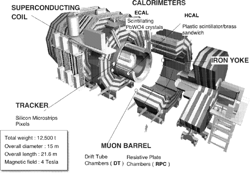
A schematic drawing of CMS is shown in Fig. 1. The total weight of the apparatus is 12500 tons. The detector, which is cylindrical in shape, has length and diameter of 21.6 m and 14.6 m, respectively. The overall size is set by the muon tracking system which in turn makes use of the return flux of a 13 m long, 5.9 m diameter, 4 Tesla superconducting solenoid. This rather high field was chosen to facilitate the construction of a compact tracking system on its interior while also allowing good muon tracking on the exterior. The return field saturates 1.5 m of iron containing four interweaved muon tracking stations. In the central region (pseudorapidity range ) the neutron induced background, the muon rate and the residual magnetic fields are all relatively small, while in the forward regions () all three quantities are relatively high. As a result, drift tube (DT) chambers and cathode strip chambers (CSC), are used for muon tracking in the central and forward regions, respectively. Resistive plate chambers (RPC) with fast response and good time resolution but coarser position resolution are used in both regions for timing and redundancy.
The bore of the magnet coil is also large enough to accommodate the inner Tracker and the calorimetry inside. The tracking volume is given by a cylinder of length 5.8 m and diameter 2.6 m. In order to deal with high track multiplicities, CMS employs 10 layers of silicon microstrip detectors, which provide the required granularity and precision. In addition, 3 layers of silicon pixel detectors are placed close to the interaction region to improve the measurement of the impact parameter of charged particle tracks, as well as the position of secondary vertices. The electromagnetic calorimeter (ECAL) uses lead tungstate (PbWO4) crystals with coverage in pseudorapidity up to . The scintillation light is detected by silicon avalanche photodiodes (APDs) in the barrel region and vacuum phototriodes (VPTs) in the endcap region. A preshower system is installed in front of the endcap ECAL for rejection. The ECAL is surrounded by a brass/scintillator sampling hadron calorimeter (HCAL) with coverage up to . The scintillation light is converted by wavelength-shifting (WLS) fibres embedded in the scintillator tiles and channeled to photodetectors via clear fibres. This light is detected by hybrid photodiodes that can provide gain and operate in high axial magnetic fields. This central calorimetry is complemented by a “tail-catcher” in the barrel region—ensuring that hadronic showers are sampled with nearly 11 hadronic interaction lengths. Coverage up to a pseudorapidity of 5.0 is provided by an iron/quartz-fibre calorimeter. The Cerenkov light emitted in the quartz fibres is detected by photomultipliers. The forward calorimeters ensure full geometric coverage for the measurement of the transverse energy in the event.
2 STATUS OF CMS (SEPTEMBER 2006)
In the current CMS Master Schedule the initial detector will be ready for first collisions in the last quarter of 2007. Installation of the pixel Tracker and the ECAL endcaps is foreseen during the 2007/2008 winter shutdown, in time for the first physics run in spring 2008. CMS has made much progress over the summer. The detector has been closed for the first time, the solenoid has been tested up to the design field of 4 T, and cosmics data have been taken simultaneously from a slice of all the sub-detectors using predominantly the final components. The items staged for design luminosity running include the fourth endcap muon station, RPC chambers at low angles, several online farm slices and the third layer of forward pixel disks.
2.1 The Magnet
The required performance of the muon system, and hence the bending power, is defined by the invariant mass resolution for narrow states decaying into muons and by the unambiguous determination of the charge for muons with a momentum of TeV. This requires a momentum resolution of at TeV.
To achieve this goal, CMS chose a large superconducting solenoid with a 4 T field [1]. The 12.9 m long and 5.9 m diameter magnet is operated with a current of 19.5 kA. The overall energy stored in the field corresponds to 2.7 GJ. The CMS magnet has been assembled on the surface and was successfully tested during the recent CMS Magnet Test and Cosmic Challenge (MTCC, see section 3).
2.2 The Muon System
Each Endcap (ME) of the Muon Detector [2] contains 234 CSCs. All of the 468 endcap CSCs have been installed on the magnet yoke disks and are now being commissioned with cosmic rays. Each trapezoidal endcap CSC chamber has 6 gas gaps containing a plane of radial cathode strips and a plane of anode wires parallel to the longest edge of the trapezoid and so, roughly perpendicular to the strips. The spatial resolution provided by each chamber ranges from 100 in Station 1 to roughly 150 in Stations 2 to 4. Wire signals are fast and are used in the Level-1 Trigger though they have coarser position resolution.
The manufacture of Barrel DT chambers is complete and almost all of the 266 DTs have been installed. The chambers installed in the barrel yokes (YB) are organized in 4 stations. Each DT chamber is piggy-backed by one or two RPCs. The chambers are staggered from station to station so that a high- muon near a sector boundary crosses at least 3 stations. The chambers consist of twelve planes of aluminum drift tubes; four measuring planes are placed above, and four below, a group of four measuring planes. Each station gives a muon vector in space with a precision of less than 100 in position and less than 1 mrad in direction. Several chambers of the barrel and endcap muon systems were successfully operated during the MTCC in July and August (see section 3 for more details).
2.3 The Tracker
The CMS Tracker [3] occupies a cylindrical volume of length 5.8 m and diameter 2.6 m. The outer portion of the Tracker is comprised of 10 layers of silicon microstrip detectors and the inner portion is made up of 3 layers of silicon pixels. Silicon provides fine granularity and precision in all regions for efficient and pure track reconstruction even in the very dense track environment of high energy jets. The three layers of silicon pixel detectors at radii of 4, 7 and 11 cm provide 3D space points that are used to seed the formation of tracks by the pattern recognition. The 3D points also enable measurement of the impact parameters of charged-particle tracks with a precision of the order of 20 in both the and views. The latter allows for precise reconstruction of displaced vertices to yield efficient b tagging and good separation between heavy and light quark jets.
The CMS Tracker continues to make good progress. Hybrid production was completed at the end of 2005, and module production was completed in the spring of 2006. In October 2006 the forward (+) half of the Tracker Outer Barrel TOB will be completed, Tracker Inner Barrel TIB+ will be ready for integration into TOB+, and Tracker EndCap TEC+ will be delivered to CERN from Aachen, where it was completed in September. In November 2006 the backward (-) half of TOB will be completed, TIB- will be ready for integration into TOB- and TEC- will be completed ready for integration into the Tracker support tube. The quality of the Tracker sub-detectors is very good. The number of dead or noisy channels is two per mille and the signal to noise ratio is . The Pixel Detector continues to make good progress. All components are now available and 15% of the modules (Barrel Pixels) and Plaquettes (Forward Pixels) have been successfully produced. A pixel sector will be delivered to CERN in December 2006 for integration before installation into CMS in September 2007. The full Pixel Detector will be ready to be installed into CMS in November 2007.
2.4 Electromagnetic Calorimeter
The ECAL [4] is a hermetic, homogeneous calorimeter comprising lead tungstate (PbWO4) crystals mounted in the central barrel part, closed by 7324 crystals in each of the 2 endcaps.
About of the barrel crystals have been delivered and are being used to construct modules (400 or 500 crystals) at CERN and in Rome. At present 122 modules out of 144 have been assembled. Thirty bare supermodules (SM, each comprising 1700 crystals) have been assembled. The crystal production is now proceeding at the rate of about 1250 crystals per month. The last Barrel crystal will be delivered by March 2007, allowing insertion of the last supermodule in May 2007. The production of Endcap crystals will start immediately after the end of the Barrel crystals production and is expected to finish by February 2008. For the Barrel electromagnetic calorimeter, the integration status is the following: During last spring, an integration rate of 4 SMs per month was achieved. Currently 24 SMs are completed, which is consistent with the general construction schedule of CMS. The performance of the integrated supermodules satisfies fully the design performance stated in the Technical Design Report. After integration, each SM is subjected to a pre-calibration and commissioning run of 10 days with cosmic muons. In addition, eight SMs have already been pre-calibrated in an electron beam. Preliminary comparisons between the cosmic and test beam data indicate that the cosmic data yield an initial inter-calibration with a precision better than 2%. Finally, two SMs have been successfully tested in the magnet of CMS during the MTCC, showing that the performance is maintained inside CMS and in the 4 T magnetic field. Large pre-series of all off-detector readout modules are in hand. Their production and testing will be completed by mid-November 2006.
2.5 Hadronic Calorimeter
All HCAL [5] module types [HB (barrel), HE (endcap), HO (outer) and HF (forward)], including absorber and optics, are completed. Photodetectors and electronics have been installed and a comprehensive calibration of HCAL using Co-60 sources has been completed. HF will be the first sub-detector to be lowered into the underground experimental cavern. This is expected to occur in October 2006. The HB and HE are fully installed. The HF has been calibrated to , HE and HB to . The HE and HB have also been run globally with muons. HCAL Trigger and DAQ have been tested with cosmics. HCAL slow controls are fully operational and data quality monitoring (DQM) is now under development and partially up and running.
2.6 Trigger and Data Acquisition
The trigger [6, 7] system is well into production with many components already completed. Components are exercised with other trigger and detector electronics systems in the Electronics Integration Center at CERN. Integration tests are run in which detector primitives are generated and used to feed the trigger and DAQ. Final system components were also used in data taking during the MTCC this summer (see section 3).
3 THE MAGNET TEST AND COSMIC CHALLENGE (MTCC)
A full-scale test and field-mapping of the CMS 4 T solenoid magnet system prior to lowering the major elements has been carried out this summer. In addition to this magnet test also a “cosmic challenge” was performed. The objective of this combined Magnet Test and Cosmic Challenge was the recording, offline reconstruction and display of cosmic muons in the 4 subsystems of CMS (Tracker, ECAL, HCAL and Muon Detector), with the magnet operating at 4 T.
The original scope was expanded to include substantial offline as well as online systems objectives. Data transfer to some Tier-1 centers, online event display, quasi-online analysis at the main CERN site, and fast offline data-checking at Fermilab were some highlighted targets of MTCC Phase I designed to offer a first hand taste of a “CMS-like” running experience.
After the cabling of the detector elements the final closing of the yoke proceeded. It was completed on 25 July allowing the start of the magnet test. The power circuit was completed and the testing of the coil progressed in steps: 5, 7.5, 10, 12.5, 15, 17.5 and then 19.12 kA to reach the nominal 4 T field on 22 August. At each value, fast discharges were provoked to learn how to tame the dumping of energy inside the cold mass during such a discharge. After running at 3.8 T for 48 hours for the cosmic challenge, the coil was run at 4 T for 2 hours on the 28 August, and the functional tests of the magnet have been declared completed with success.
Twenty five million cosmic triggered events were recorded with the
principal subdetectors active, of which 15 million events have stable
field of 3.8 T. Data-taking efficiency reached over 90% for
extended periods. Several thousand of these events correspond to the
“4-detector” benchmark, and the whole data sample will provide useful
understanding and calibration of the combined detector and software
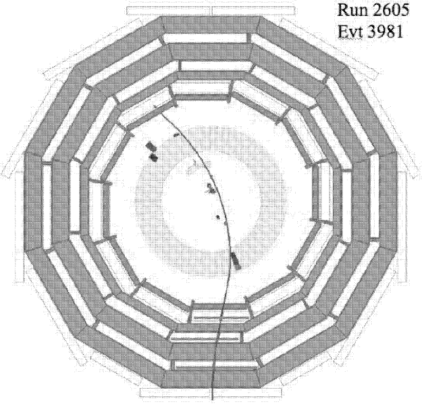
performance. A characteristic event display of a cosmic muon that left
signatures in all four active detector elements (Tracker, ECAL, HCAL
and Muon Detector) is shown in Fig. 2. The shown
trajectory corresponds to the result of the standalone muon
reconstruction. In the inner detector this trajectory coincides
within the expected uncertainties with the ECAL, HCAL and
Tracker measurements demonstrating that the propagation of the
standalone muon information was successfully carried out. The main
conclusions of the successful MTCC are:
– CMS can be opened and closed on the timescales intended;
– The magnet worked stably and safely at 4 T;
– The subdetectors work with the magnet and each other;
– The subdetectors can be integrated with the central DAQ, trigger, DCS, DQM etc.;
– The commissioning strategy broadly worked;
– CMS can work as a world-wide, unified team.
| Luminosity | |||||
|---|---|---|---|---|---|
| Time | few weeks | 6 months | 1 day | few weeks | one year |
| Int. Luminosity | |||||
| 700K | 7M | 100K | 7M | 70M | |
| 100K | 1M | 20K | 1M | 10M | |
4 CMS COMMISSIONING STRATEGY
Once CMS is fully installed in the underground cavern, a comprehensive program of commissioning has to be carried out in order to optimize the detector performance, and to prepare it for an optimal exploitation of its physics potential.
The commissioning program includes the precise calibration of the ECAL and HCAL calorimeters, the alignment of the tracking and muon detectors and the definition of an efficient and flexible trigger setup. Once the detector is aligned and calibrated, physics tools such as b-tagging and missing measurement can be commissioned.
4.1 LHC Schedule
Recently, the LHC start-up schedule has been revised [8]. The closing of the experiments will be followed by the start-up and initial commissioning of the LHC accelerator with single beams at in autumn 2007. In December 2007, a 2-3 week “calibration run” will be carried out with collisions at and low specific luminosities .
After the winter shutdown, LHC operation will be continued with commissioning at and a three-stage running scenario: (1) a one-month “pilot physics run” at ; (2) pushing of the machine parameters in order to increase the specific luminosity to ; (3) towards the end of 2008 the luminosity could be pushed to the nominal value.
4.2 Commissioning Data Samples
From the CMS commissioning point of view three distinct phases can be
identified, which give access to complementary data sets:
– No beams: Accumulation of large
samples of cosmic muons, which are very beneficial e.g. for Tracker
and muon barrel alignment.
– Single beams: Single beams give rise
to beam halo muon and beam-has events. The near-horizontal beam halo
muons can be used for Tracker and muon end-cap alignment. Beam-gas
interactions can be used for various commissioning tasks.
– Colliding beams: LHC collisions will provide
a cocktail of physics events, depending on the specific
luminosity. For commissioning purposes, muons and electrons from
decays, but also minimum bias and QCD jet events are
useful.
During the low-luminosity 2007 calibration run at , the available data will be completely dominated by minimum bias and QCD jet events. At most a few tens of events can be expected in this phase. However, the 2008 pilot run will see substantial rates of events (Tab. 1). Large samples of high muons from these events can thus be accumulated within a short timescale and used e.g. for alignment.
4.3 CMS Commissioning Strategy
The main CMS commissioning goals are: (1) Efficient operation of trigger and DAQ; (2) Tracker and Muon alignment; (3) Calorimeter calibration. Once these goals are achieved, the commissioning of higher level physics tools and objects such as b-tagging, jets, missing can proceed.
Provided a sufficient amount of physics, cosmics and beam-halo/gas events can be accumulated, a lot of important commissioning tasks can be performed already during the 2007 calibration run: Trigger and DAQ can be timed in, synchronized and their data integrity be checked. The trigger algorithms can be debugged and improved. ECAL and HCAL can be calibrated to . Tracks from cosmic and beam halo muons as well as collision tracks can be used to align the Tracker to significantly better than , and to align the muon chambers.
However, important commissioning tasks can only be carried out in 2008: The final HCAL and ECAL calibrations, the final Tracker alignment (the pixel detector will only be installed in 2008) and the commissioning of b-tagging, missing etc.
5 MAJOR COMMISSIONING TASKS
Details on the commissioning procedures as well as the physics potential can be found in [9, 10]. In the following, a few aspects of the major commissioning tasks are highlighted.
5.1 Trigger and DAQ
The CMS trigger consists of the hardware based Level-1 trigger (nominal accept rate ) using calorimeter and muon signals, and of the High Level Trigger (HLT), a massively parallel processor farm in which the full event information is available. The HLT reduces the rate by three orders of magnitude to which are sent to the Tier-0 centre for prompt reconstruction.
An efficient operation of the trigger is ensured if both ECAL and HCAL are calibrated to the level of , the muon detector is aligned to , and the silicon Tracker is aligned to (for HLT b-tagging). Most of these requirements can be met already during the 2008 pilot run.
Trigger tables [7] for low and high luminosity running have been prepared and are currently being refined. In addition, trigger scenarios for the 2007 and 2008 calibration and pilot runs are being prepared, with a focus on commissioning triggers.
The data reconstructed at the Tier-0 are split in streams [11], according to their physics content. Particularly important for commissioning purposes is the express stream, which is defined to have a fast turn-around time. Its purpose is to provide fast feedback on any possible interesting high mass signals, but also to provide data sets used for alignment and calibration.
5.2 Tracker Alignment
The CMS Silicon Tracker consists of silicon strip and pixel sensors covering an active area of . This large number of independent silicon sensors and their excellent intrinsic resolution of make the alignment of the CMS Tracker a complex and challenging task.
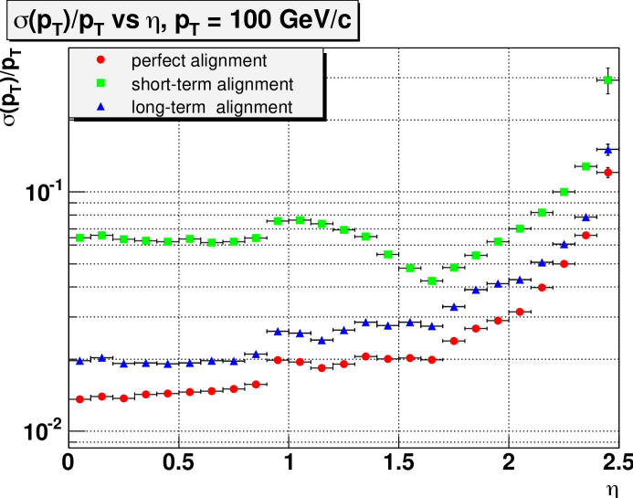
5.2.1 Impact of Misalignment
Misalignment will degrade the track parameter resolution and hence affect the physics performance of the Tracker, for instance the mass resolution of resonances or the b-tagging performance. To assess the impact of misalignment on the tracking and vertexing performance, Two misalignment scenarios have been implemented [12, 13], which are supposed to mimic the conditions for different data taking conditions, namely the First Data Taking Scenario and the Long Term Scenario (Fig. 3).
5.2.2 Alignment
The alignment strategy for the CMS Tracker foresees that in addition to the knowledge of the module positions from measurements at construction time, the alignment will proceed by means of a Laser Alignment System (LAS) and track-based alignment. The LAS uses infrared laser beams and operates globally on the larger Tracker composite structures. It cannot determine the positions of individual modules. The goal of the LAS is to provide measurements of the Tracker substructures at the level of as well as monitoring of possible structure movements at the level of .
Track-based alignment represents a major challenge at CMS because the
number of degrees of freedom to be determined with a precision of
is . Three different
algorithms for alignment with tracks are used in CMS:
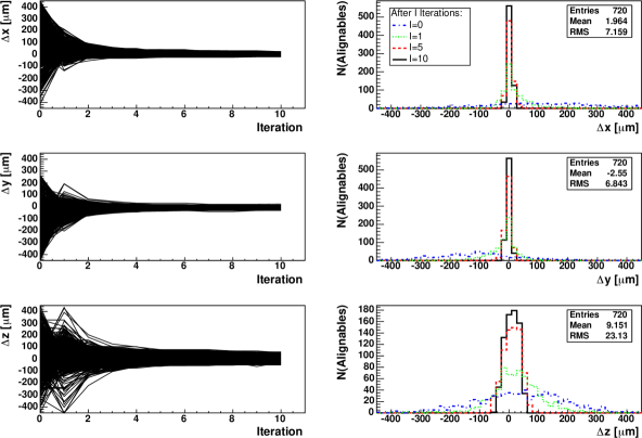
– HIP algorithm: Minimization of
a local function on each sensor [14]. Correlations
between different sensors are not explicitly included, but taken care
of implicitly using iterations. No inversions of large matrices are
involved (Fig. 4).
– Millepede-II:
A global linear least-squares algorithm which takes into account
correlations among parameters. For alignment parameters the
solution requires the inversion of a matrix. A new
version, Millepede-II, was developed [15] which offers
additional solution methods and is expected to be scalable to the
full CMS Tracker alignment problem within reasonable CPU time.
– Kalman filter:
A method for global alignment derived from the Kalman filter. It is
iterative and avoids inversions of large
matrices [16]. The alignment parameter update can be
extended to those elements that have significant correlations with the
ones in the current track.
The current alignment strategy foresees that cosmics and beam halo muons can be used to carry out an initial alignment of the strip Tracker in 2007, which could be improved using high collision tracks when available. When larger samples of muons from decays become available in 2008, a standalone alignment of the by then installed pixel detector can be performed, followed by the precise alignment of the strip Tracker, using the pixel detector as a reference system.
5.3 Muon Alignment
The CMS Muon system consists of 790 individual chambers with an intrinsic resolution in the range . Excellent alignment of the Muon system is particularly important to ensure efficient muon triggering and good track momentum resolution at large momenta.
For optimal performance of the Muon spectrometer over the entire momentum range up to 1 TeV, the different muon chambers must be aligned with respect to each other and to the Tracker to within . To control misalignment during commissioning and to monitor further displacements during operation, CMS will combine measurements from an optical-mechanical system with the results of track based alignment [17].
5.4 Calorimeter Calibration
Precise calibration of the ECAL and HCAL calorimeters is a key ingredient for precise measurements of photons, electrons, hadrons, jets and missing . Certain physics channels, such as , impose very tight requirements such as the ECAL calibration being known to the level of . On the other hand typical SUSY signatures involve final states with jets and missing , measured using the HCAL. The knowledge of the energy scale for b-jets is crucial for top quark mass measurements.
HCAL will be pre-calibrated to the level of using a radioactive source. This calibration will be improved upon using minimum bias events for HCAL uniformity, from high isolated tracks extrapolated from the Tracker, and di-jet balance for regions not covered by the Tracker acceptance [9].
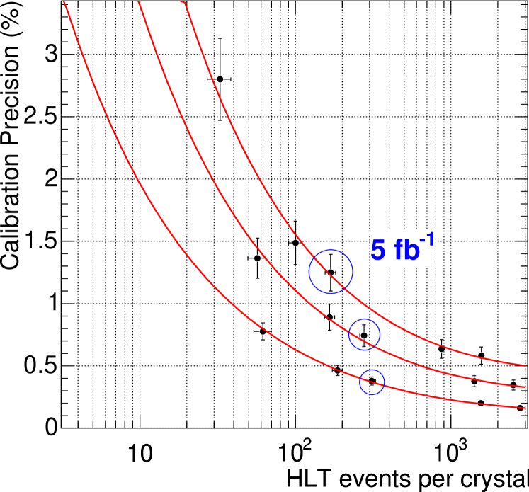
For ECAL, a pre-calibration using test beam and light-yield measurements as well as cosmics will be performed to a precision of around . During the 2007 calibration run, it is envisaged to set up a dedicated minimum bias event stream with a bandwidth of . Using phi symmetry as well as decays, the calibration can be improved quickly. The ultimate ECAL calibration precision will be reached from the 2008 pilot physics run onwards, using the method with high momentum electrons from decays (see Fig. 5). Studies using full simulation have shown that a precision of can be achieved in the barrel using of data [18].
6 EARLY PHYSICS WITH CMS
Provided the commissioning tasks can be be performed successfully, there is an exciting potential for early physics with CMS [10]. Here, only two examples can be highlighted:
6.1 Top Physics
Since the top quark pair production cross section is very large at the LHC (), top physics is an early physics topic for CMS. Cross section and mass measurements will be possible in all major decay channels. For , events are expected in the dilepton channel. A cross section measurement at the level, as well as a mass measurement to will be possible [19], the systematic error being dominated by the b-jet energy scale uncertainty. At , the top mass can be measured to in the semileptonic channel [20], provided the b-jet energy scale is known to . These examples illustrate the importance of the commissioning of physics tools such as b-tagging (alignment) and jet energy scale (calibration).
6.2 High Mass Dileptons
Resonances at high mass in dilepton final states are very interesting for early discoveries since they could potentially show up at luminosities as low as a few . High mass dileptons (where ) are predicted by various new physics scenarios. Simulations show [10] that a resonance in the di-muon mass spectrum could be discovered within a few weeks of data taking. However, for a measurement of the mass of the resonance and to separate it from the continuum background, a very good alignment of the Tracker and muon detectors is crucial.
7 ASPECTS OF B-PHYSICS
7.1 b-Tagging Performance
Various b-tagging algorithms have been implemented in the CMS
reconstruction software and their performance evaluated
in [9]. Both lifetime as well as soft lepton ( and
) tags have been studied. The lifetime-tag based algorithms
are:
– Track counting: Robust algorithm which counts
the number of tracks in a jet with impact parameter above a given
threshold;
– Probability: Calculates the probability that a set of tracks
originate from the primary vertex;
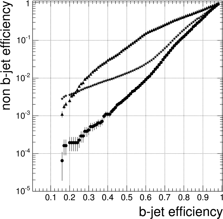
– Combined secondary vertex tag: Reconstructs
the secondary vertex of the b hadron decay and combines
several discriminating variables [21]
(Fig. 6).
All lifetime based algorithms require that the pixel detector has been aligned with tracks.
7.2 Sensitivity to
A new study of the CMS sensitivity to the rare decay has been performed [22]. It uses a dedicated HLT trigger (accept rate ) and a cut-based offline analysis. For a signal efficiency of , a background rejection of is obtained. For this corresponds to signal (background) events. The corresponding C.L. upper limit on the branching fraction is , including systematic errors.
8 CONCLUSIONS
The construction and installation of the CMS detector is making very good progress, demonstrated for instance by the successful Magnet Test and Cosmic Challenge carried out in the summer of 2006. Following the installation of CMS, the LHC 2007 calibration run and 2008 pilot physics run must be used for detector commissioning. Important examples are the trigger and DAQ system, Tracker and Muon alignment and calorimeter calibration. The commissioning of physics tools relies on the success of these tasks. There is an exciting program for early physics with CMS.
References
- [1] CMS Coll., “Magnet Technical Design Report”, CERN/LHCC 1997-010 (1997).
- [2] CMS Coll., “Muon Technical Design Report”, CERN/LHCC 1997-032 (1997).
- [3] CMS Coll., “Tracker Technical Design Report”, CERN/LHCC 1998-006 (1998); Addendum CERN/LHCC 2000-016 (2000).
- [4] CMS Coll., “ECAL Technical Design Report”, CERN/LHCC 1997-033 (1997).
- [5] CMS Coll., “HCAL Technical Design Report”, CERN/LHCC 1997-031 (1997).
- [6] CMS Coll., “L1 Trigger Technical Design Report”, CERN/LHCC 2000-038 (2000).
- [7] CMS Coll., “Data Acquisition and High-Level Trigger Technical Design Report”, CERN/LHCC 2002-026 (2002).
- [8] http://lhc-commissioning.web.cern.ch/lhc-commissioning/
- [9] CMS Coll., “Physics Technical Design Report Vol. 1: Detector Performance and Software”, CERN/LHCC 2006-001 (2006).
- [10] CMS Coll., “Physics Technical Design Report Vol. 2: Physics Performance”, CERN/LHCC 2006-021 (2006).
- [11] D. Acosta et al., CMS Note 2006/095.
- [12] I. Belotelov et al., CMS Note 2006/008.
- [13] P. Vanlaer et al., CMS Note 2006/029.
- [14] V. Karimaki et al., CMS Note 2006/018.
- [15] P. Schleper et al., CMS Note 2006/011.
- [16] R. Fruehwirth et al., CMS Note 2006/022.
- [17] A. Calderon et al., CMS Note 2006/016.
- [18] L. Agostino et al., CMS Note 2006/021.
- [19] M. Davids et al., CMS Note 2006/077.
- [20] J. D’ Hondt et al., CMS Note 2006/066.
- [21] C. Weiser, CMS Note 2006/014.
- [22] C. Eggel et al., CMS CR 2006/071.