Event Rates for Off Axis NuMI Experiments
Abstract
Neutrino interaction rates for experiments placed off axis in the NuMI beam are calculated. Primary proton beam energy is 120 GeV and four locations at 810 km from target and 6, 12, 30 and 40 km off axis are considered. This report is part of the Joint FNAL/BNL Future Long Baseline Neutrino Oscillation Experiment Study.
1 Introduction
A generic calculation of neutrino event rates for detectors at various locations in the NuMI neutrino beam has been done. Only flux, probability, cross sections and rudimentary energy reconstruction is considered. No particular detector technology is assumed.
2 Baselines
This document gives a calculation of neutrino flux and interaction rates for detectors placed in the various locations in the NuMI beam at 810 km from the target. Four off-axis locations are considered: 6 km (7.4 mrad), 12 km (14.8 mrad), 30 km (37.0 mrad) and 40 km (49.4 mrad).
3 Neutrino Flux
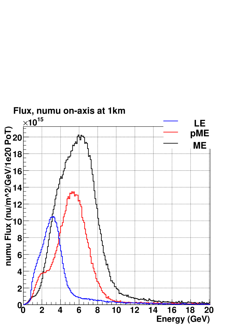
Neutrino flux calculations are performed using the GEANT3 based GNUMI simulation program. The proton beam, target, focussing horns, decay tunnel and other elements are models of what is currently in use by MINOS. The locations of the two focusing horns with respect to the target can focus the neutrino parents to produce different spectra. The so called “Low Energy” (LE)111More properly, MINOS calls this “LE-10” and “pseudo Medium Energy” (pME) tuning are used to confirm the simulation against measured MINOS near detector data while the “Medium Energy” tuning is used for spectra at 810 km to match. Table 1 summarizes the beam tunings used. In all cases a 120 GeV primary proton beam is used.
| Name | Target (cm) | Horn 2 (m) | Current (kA) | Version |
|---|---|---|---|---|
| LE | -10 | +10 | 182 | v18 |
| pME | -100 | +10 | 197 | v18 |
| ME | -100 | +13 | 182 | v15 |
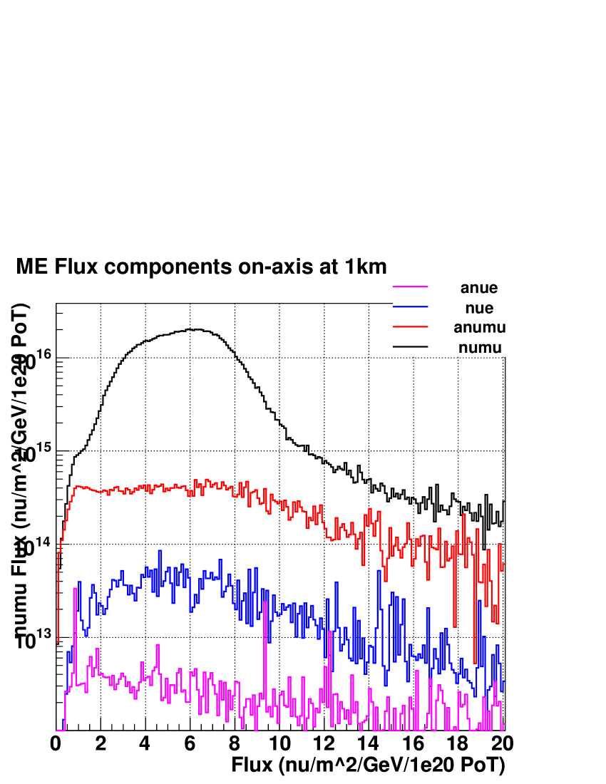
Figure 1 shows the spectra for these three beam configurations. Figure 2 shows the four neutrino components of the flux for the ME configuration.
4 Oscillation Probability
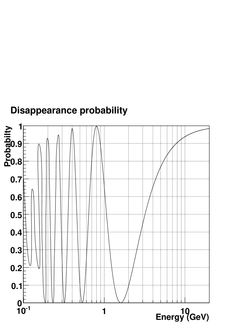
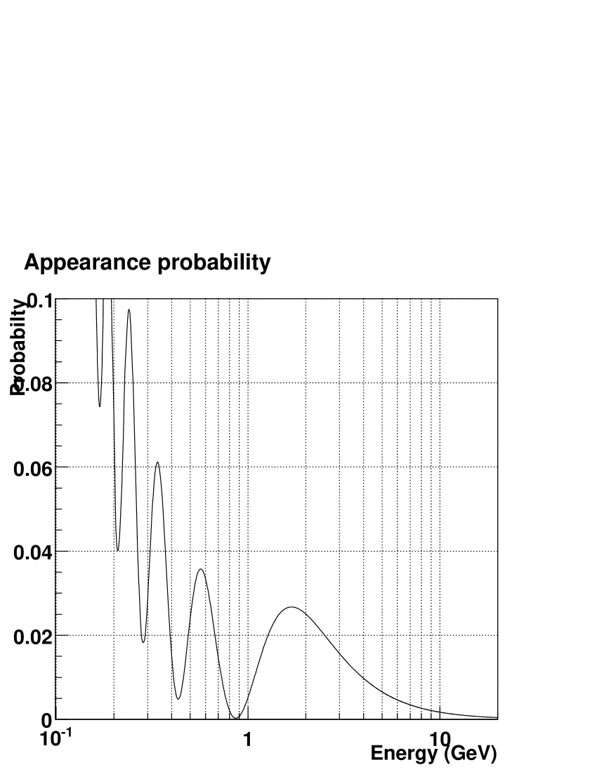
For this study, the neutrino oscillation parameters that were used are given in Table 2. They were calculated using the program “nuosc” part of libnuosc++[1]. This calculation is a full three-neutrino numerical calculation using the Preliminary Reference Earth Model (PREM)[2] for Earth’s density. The calculation mode using constant matter densities averaged over the baseline was used. Figure 3 shows the disappearance and appearance probabilities used.
| Parameter | Value |
|---|---|
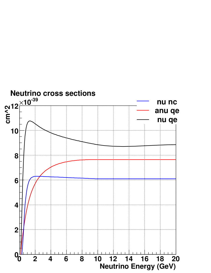
5 Cross Sections
The interactions considered are:
-
•
Quasi-elastic (QE) charged current (CC)
-
•
Total charged current
-
•
Neutral current (NC) single productions (1)
The cross sections used for QE and NC-1 are shown in Figure 4. The total CC cross sections are parameterized for neutrinos as:
and anti-neutrinos as:
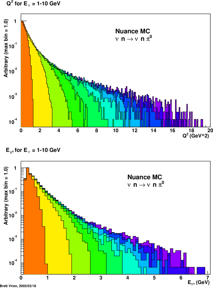
The neutrino energy in charged current (total and QE) events is assumed to be reconstructed with perfect energy resolution and with no systematic bias. For NC-1 events the reconstructed neutrino energy is taken to be the true energy of the and no consideration for shower angle w.r.t. to the incoming neutrino is made. This produces a softer reconstructed energy spectrum than would be found if this angle were considered. In addition, no account of nuclear absorption nor charge exchange by the is made.
To simulate the energy of the sets of spectra were generated using mono-energetic neutrinos with energies chosen in steps of 0.5 GeV. These were generated with the NUANCE[3] simulation. Figure 5 illustrates this.
All cross sections are applied assuming the detector mass is made up of equal numbers of protons and neutrons.
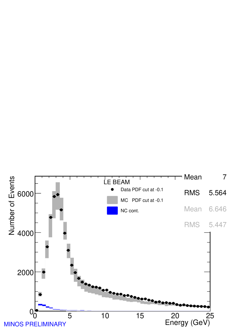
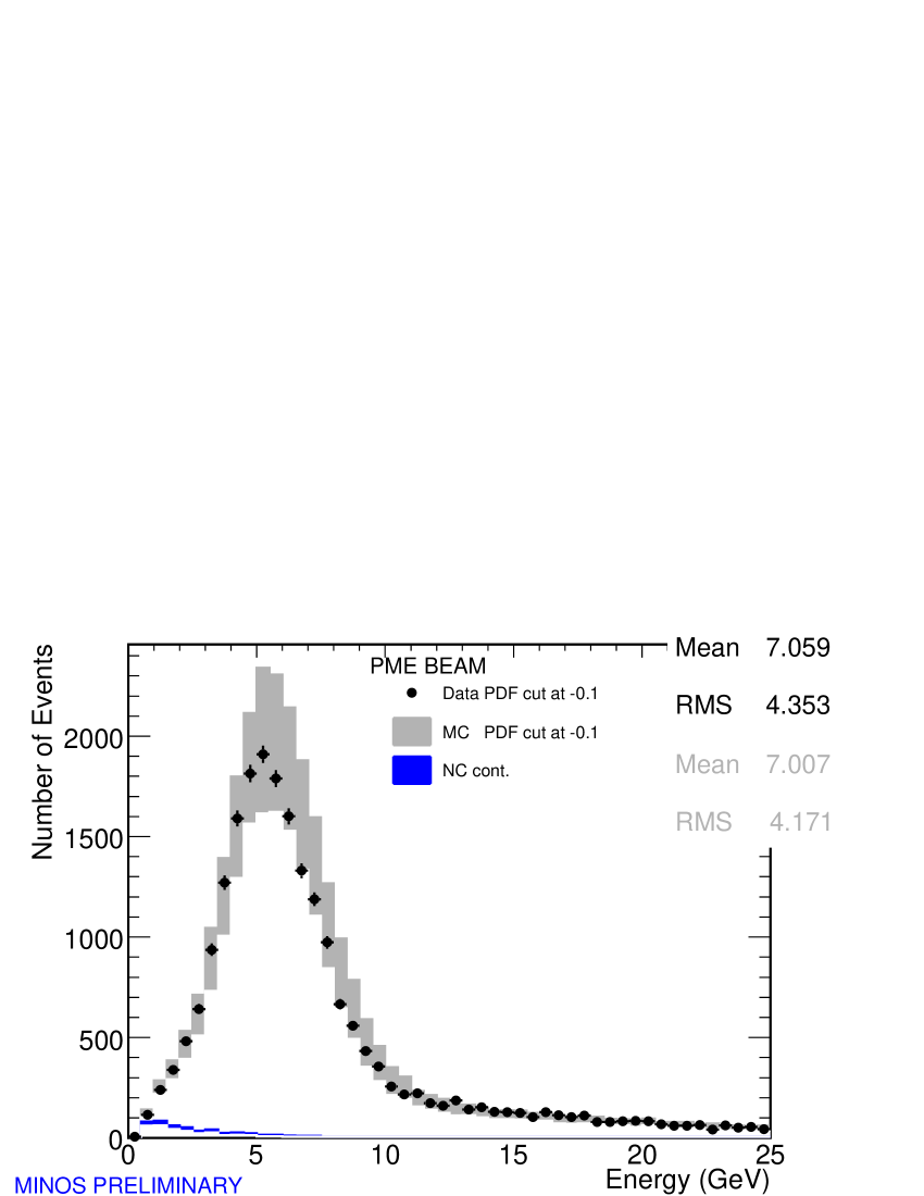
6 Comparison with MINOS Near Detector Data
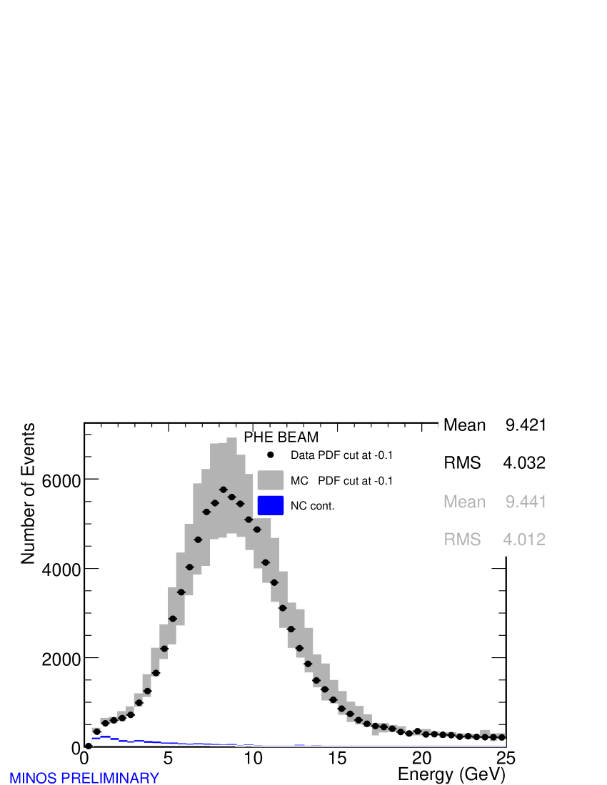
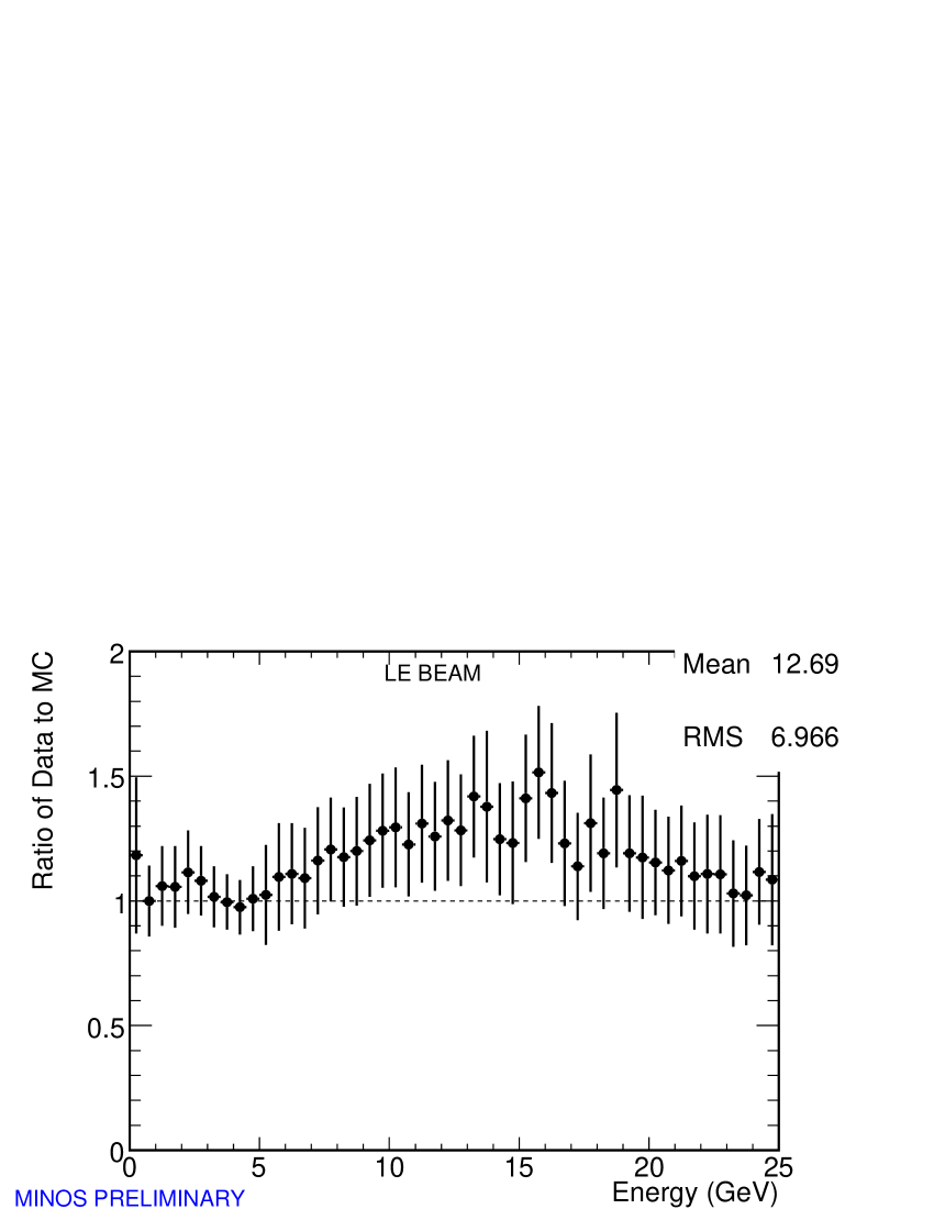
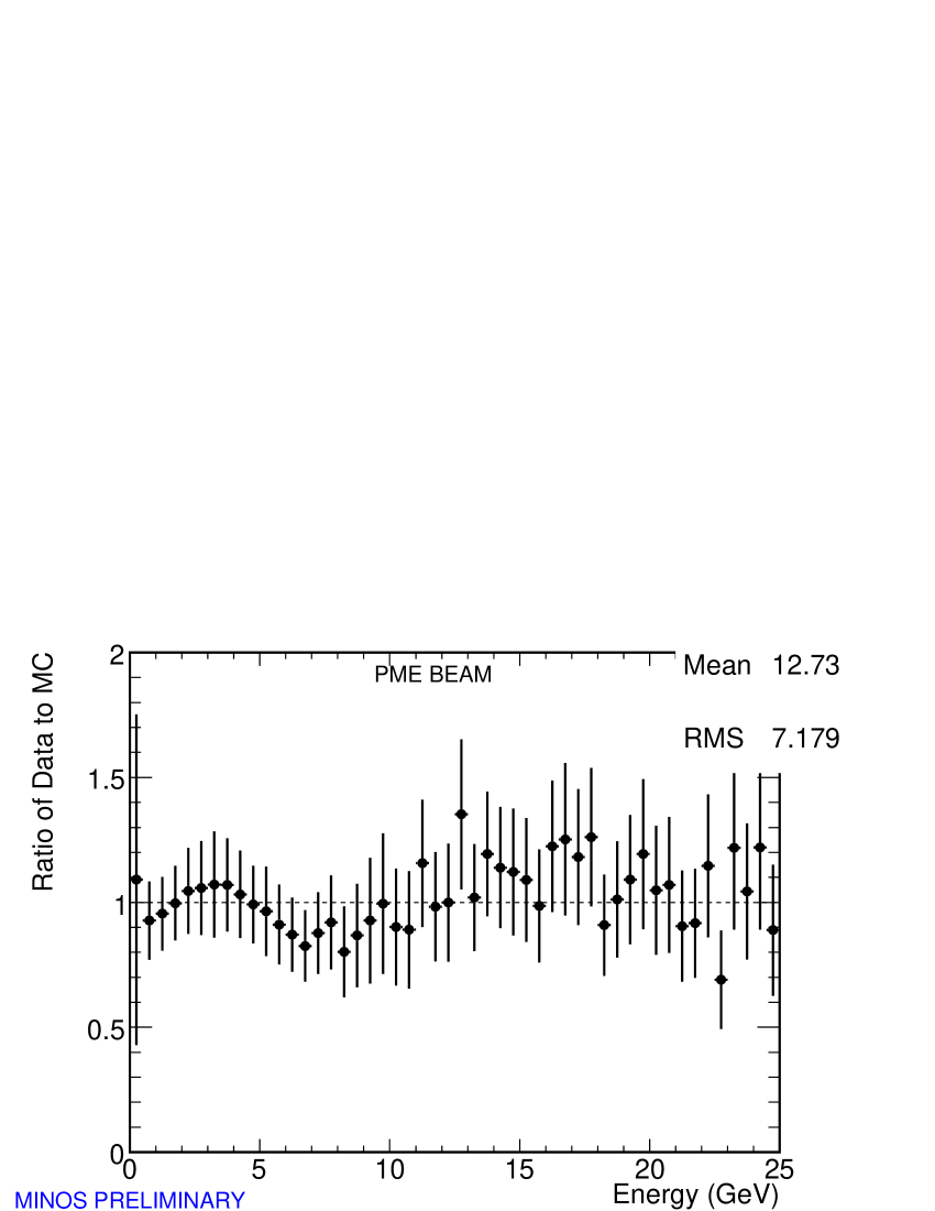
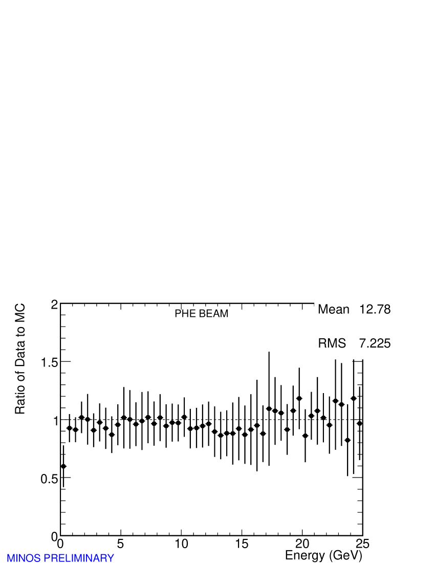
Figure 6 shows a comparison between GNUMI MC simulation and data collected in the MINOS near detector. There “LE-10” corresponds to the “LE” configuration in this work. The ME simulation used in this work is from a slightly older version (v15) of GNUMI than is used in this comparison (v18). No tuning to the MINOS data has been done and data/MC comparison shows very good agreement.
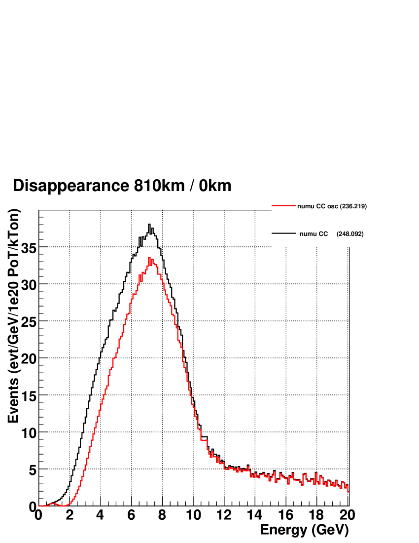
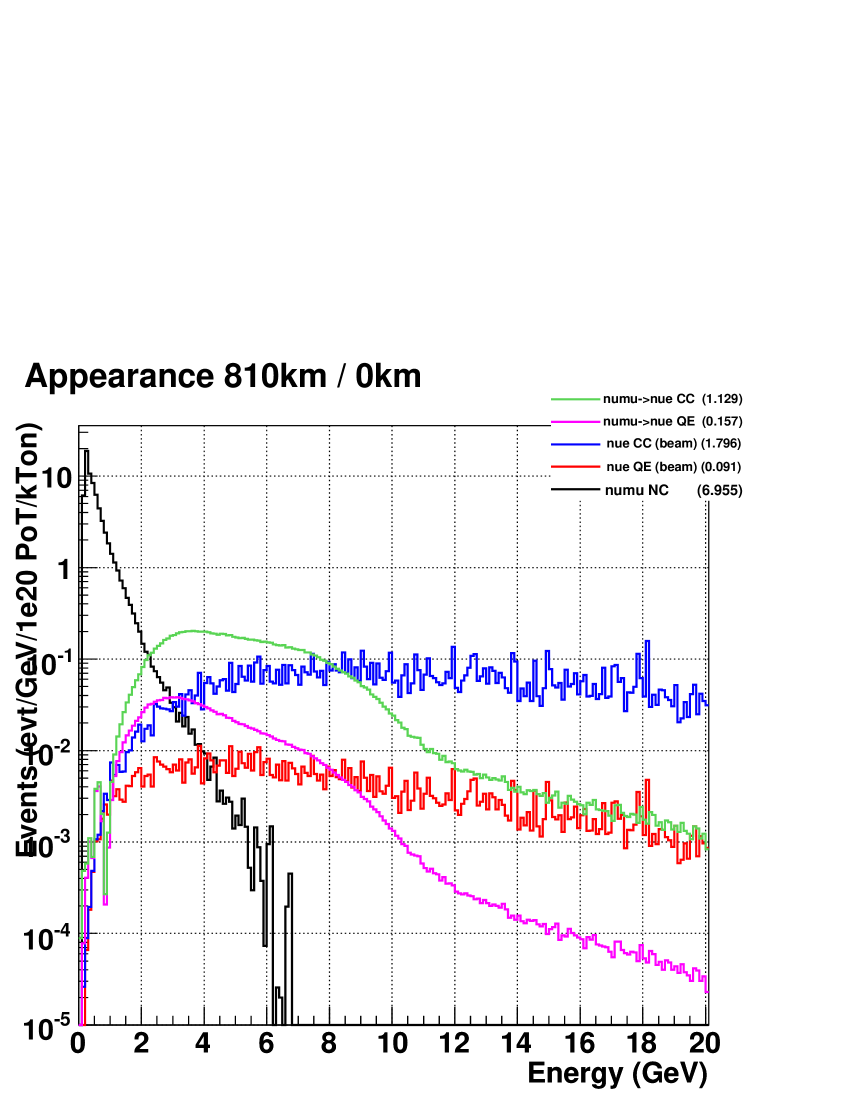
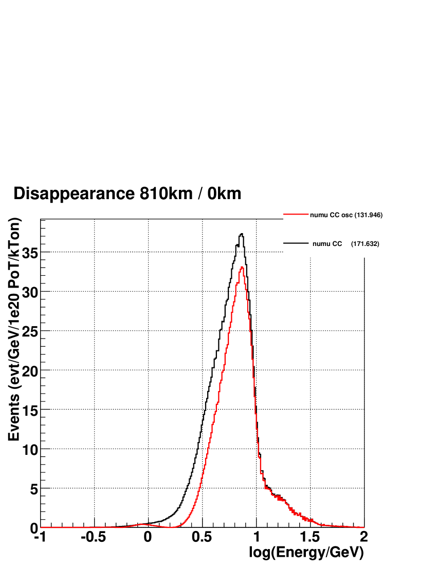
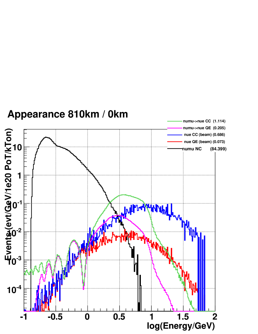
7 Off-axis Event Rates
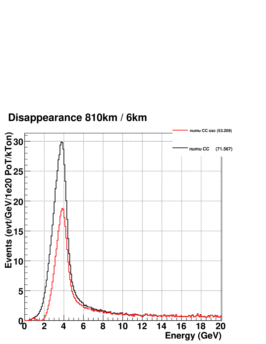
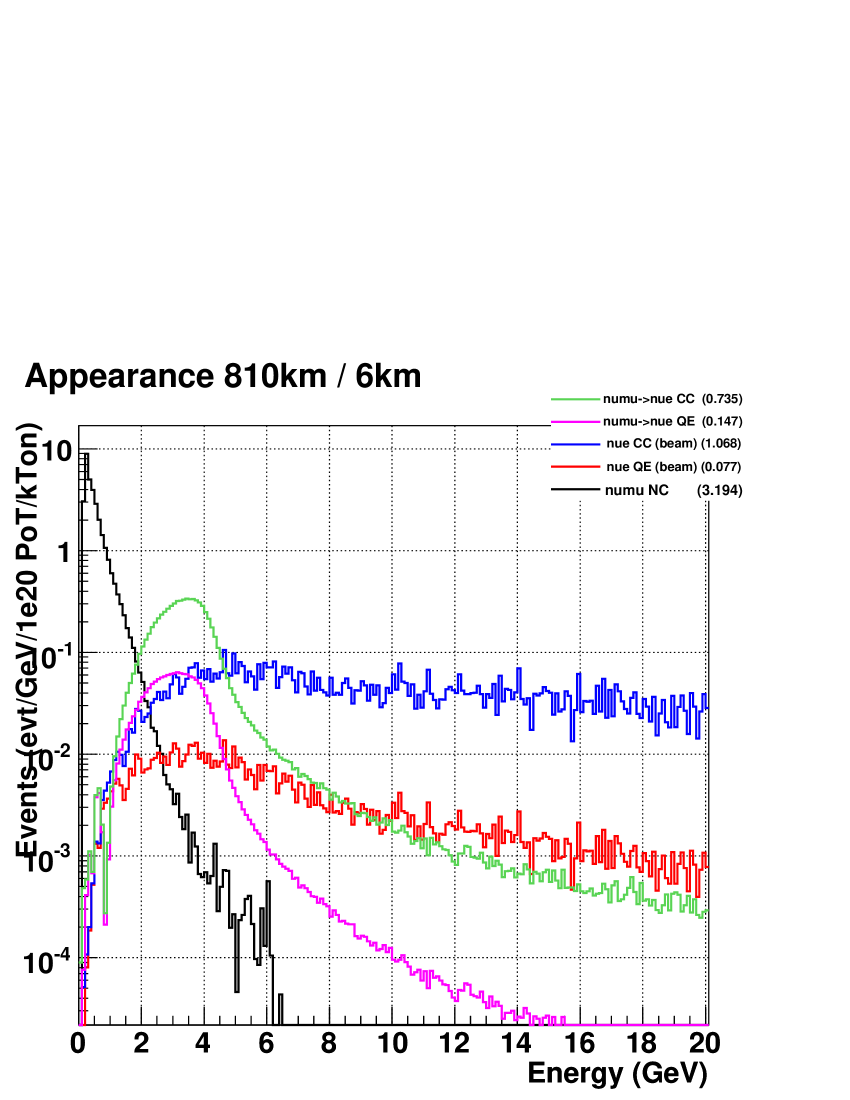
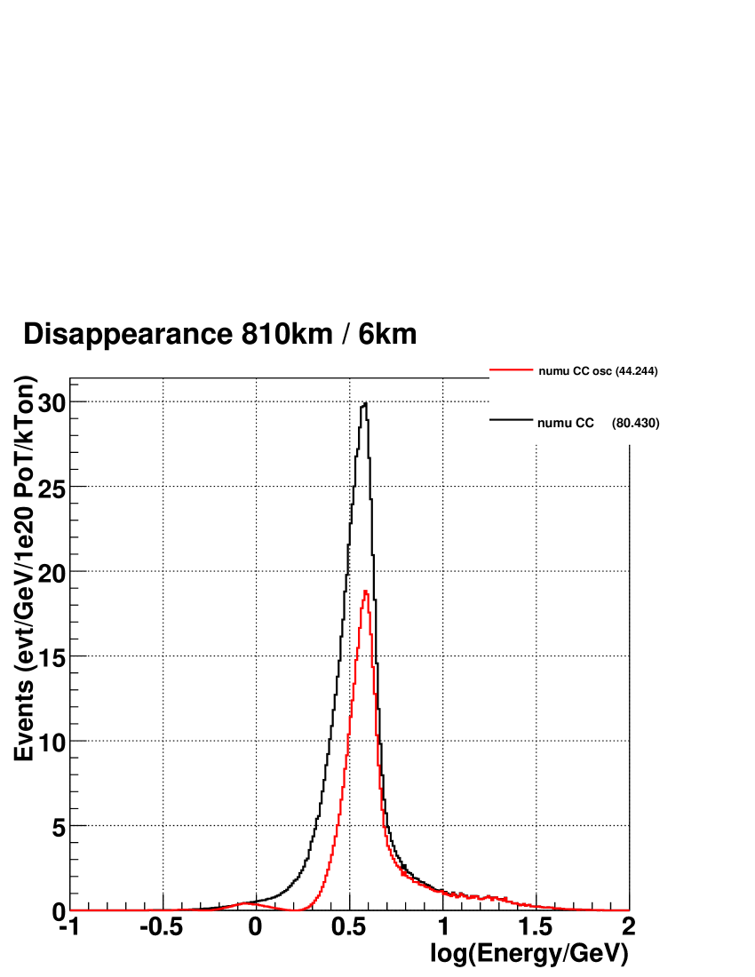
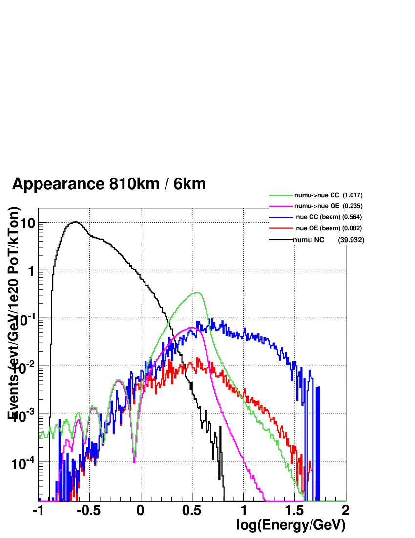
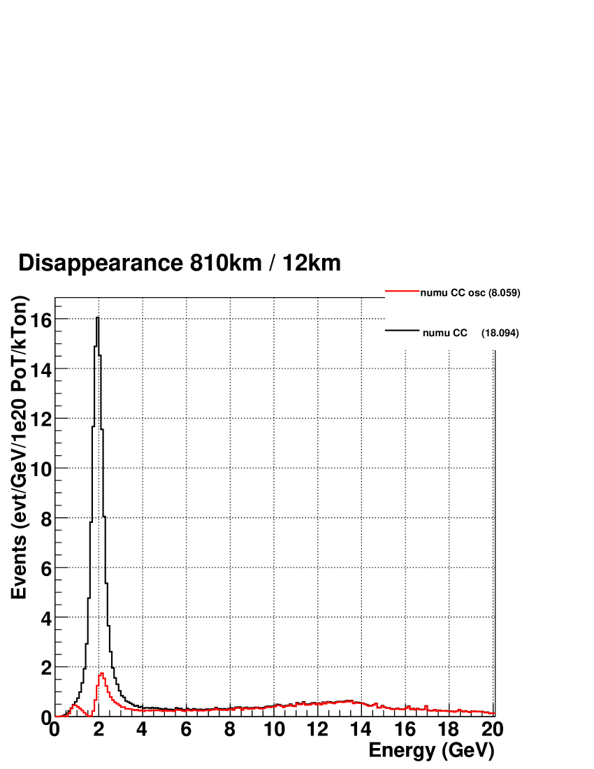
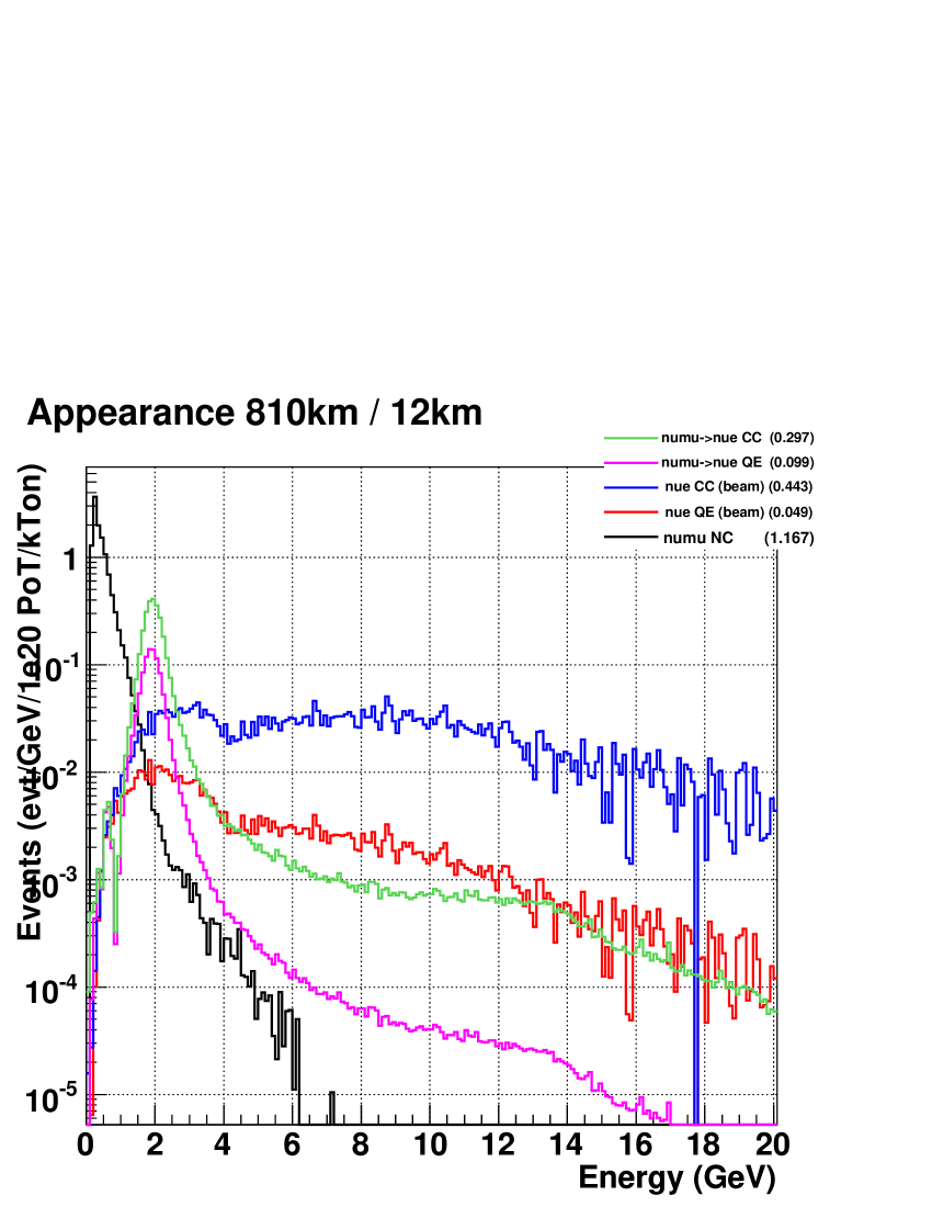
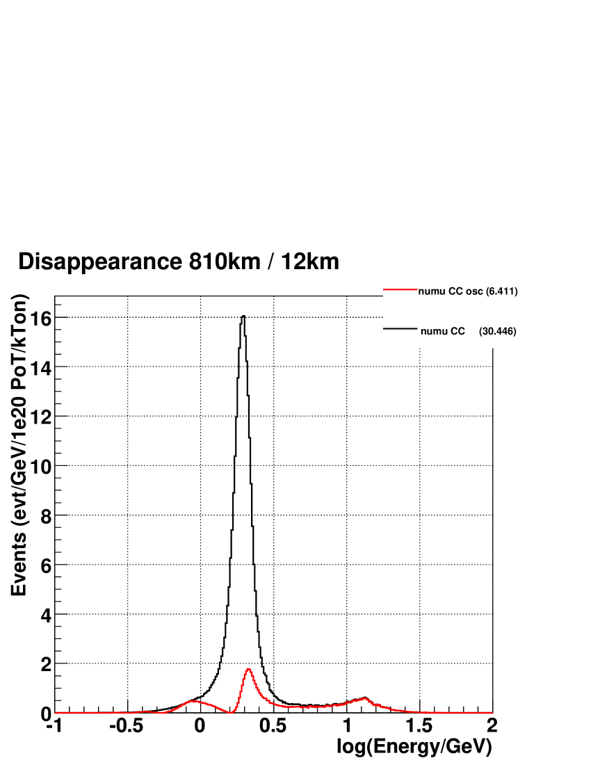
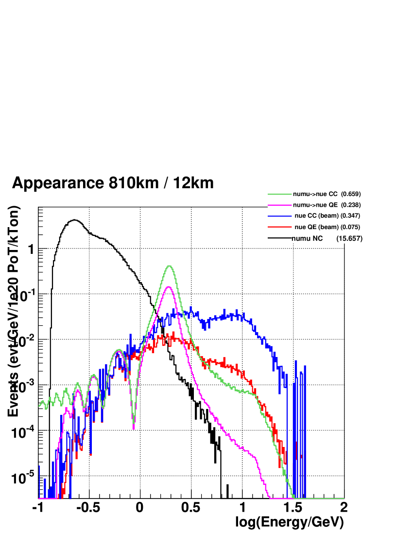
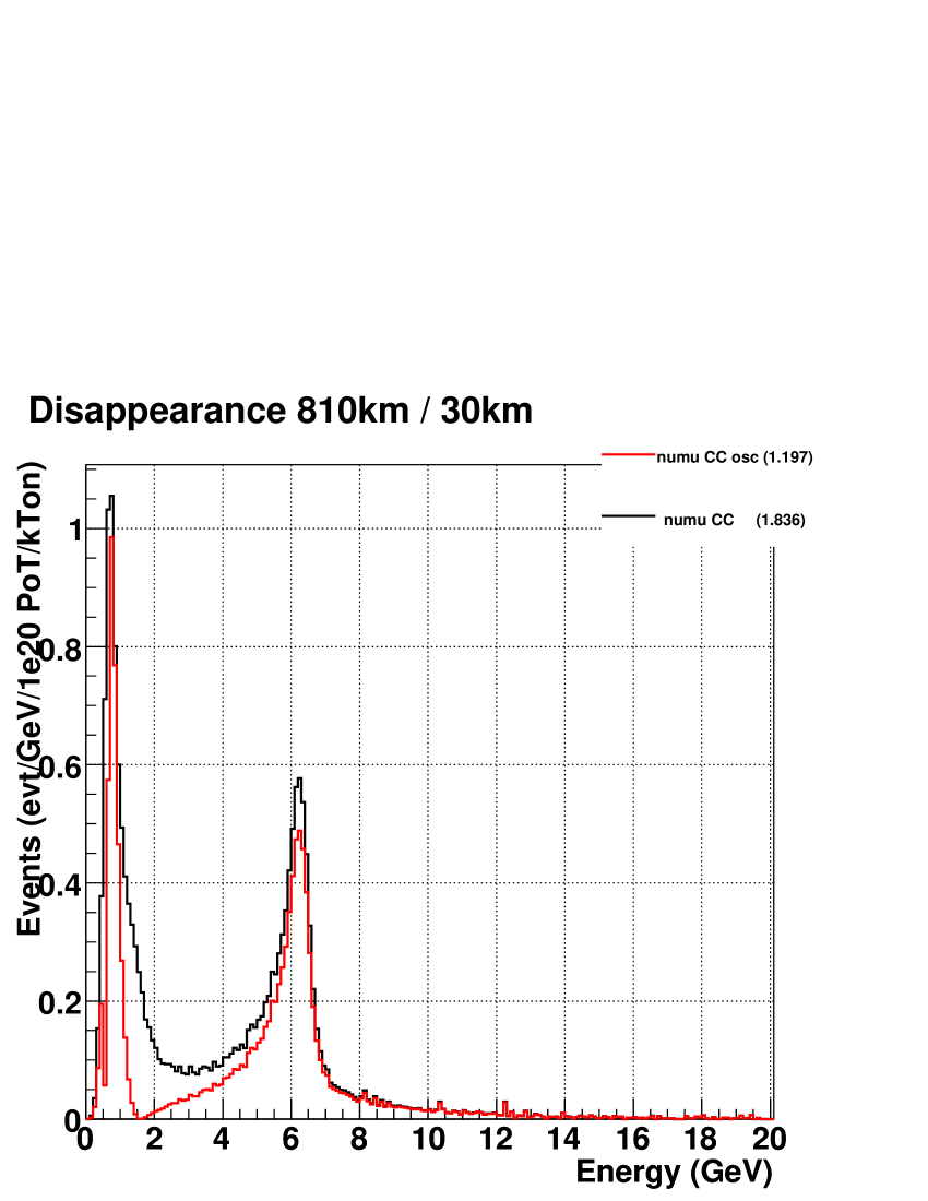
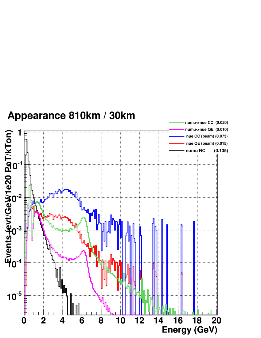
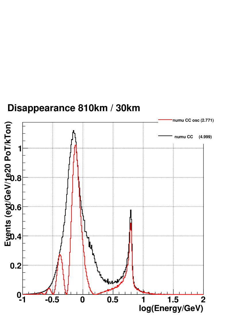
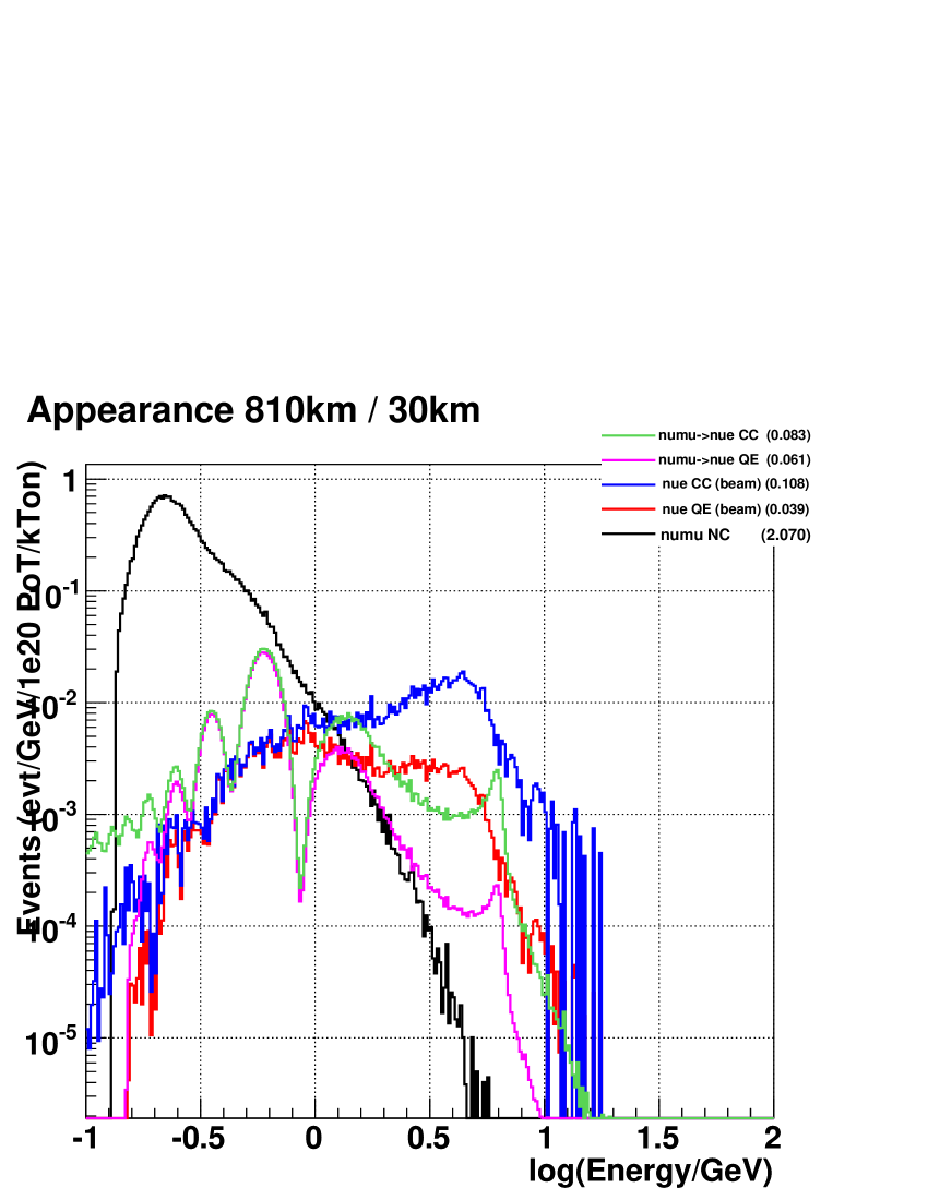
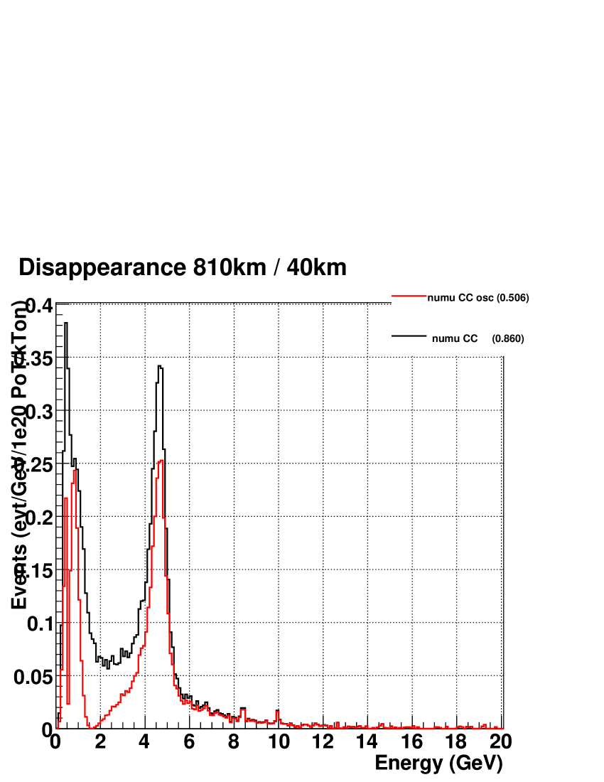
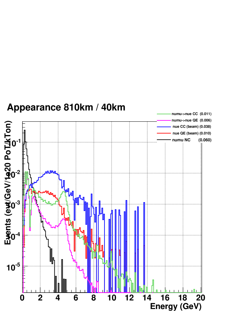
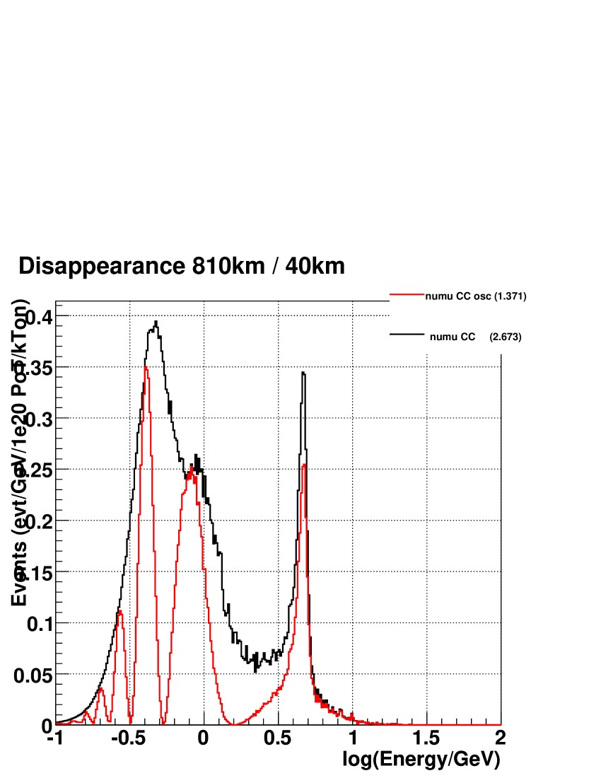
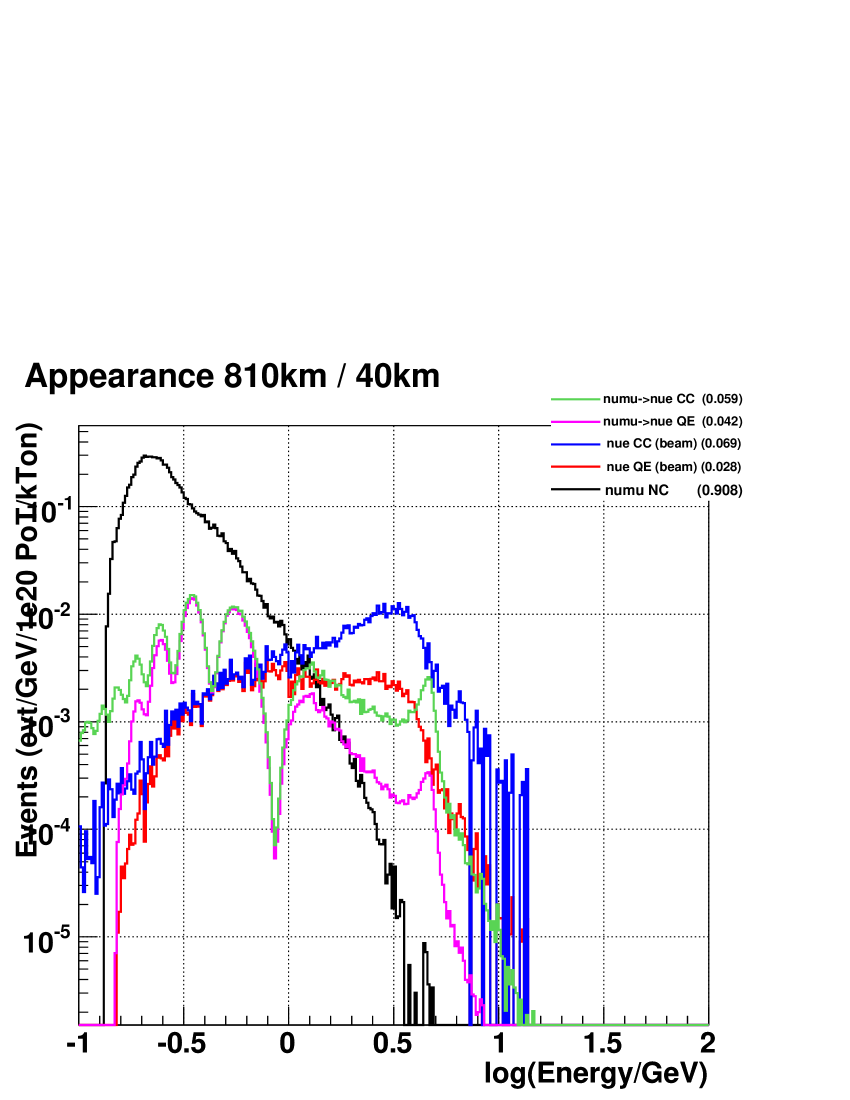
All of the above is combined to estimate interaction spectra and rates for disappearance and appearance modes for detectors placed in the NuMI beam. Figures 7-16 show these spectra for an 810km baseline at 0, 6, 12, 30 and 40 km off axis. The event rates are summaries in Table 3.
| km o.a. | CC | CC osc | CC beam | QE beam | NC- | CC | QE | |||||||
|---|---|---|---|---|---|---|---|---|---|---|---|---|---|---|
| 0 | 248. | 0 | 225. | 0 | 1. | 80 | 0. | 0914 | 6. | 96 | 1. | 40 | 0. | 188 |
| 6 | 71. | 6 | 47. | 0 | 1. | 068 | 0. | 0770 | 3. | 194 | 0. | 879 | 0. | 171 |
| 12 | 18. | 1 | 7. | 33 | 0. | 443 | 0. | 0485 | 1. | 168 | 0. | 305 | 0. | 099 |
| 30 | 1. | 84 | 1. | 12 | 0. | 0730 | 0. | 0152 | 0. | 135 | 0. | 0216 | 0. | 0108 |
| 40 | 0. | 860 | 0. | 479 | 0. | 0378 | 0. | 0097 | 0. | 0605 | 0. | 0121 | 0. | 0057 |
References
- [1] “libnuosc++ - A library for calculating 3 neutrino oscillation probabilities.”, B. Viren, http://nwg.phy.bnl.gov/ bviren/elbo/libnuosc++/README.
- [2] A. M. Dziewonski and D. L. Anderson, “Preliminary Reference Earth Model,” Phys. Earth Planet. Interiors 25, 297 (1981).
- [3] D. Casper, Nucl. Phys. Proc. Suppl. 112, 161 (2002), hep-ph/0208030.
- [4] “Joint Experimental/Theoretical Physics (Wine and Cheese) Seminar”, Fermilab 2006 March 30, D. Petyt for the MINOS Collaboration