Test experiment to search for a neutron EDM by the Laue diffraction method
Abstract
A prototype experiment to measure the neutron electric dipole moment (nEDM) by spin-rotation in a non-centrosymmetric crystal in Laue geometry was carried out in order to investigate the statistical sensitivity and systematic effects of the method. The statistical sensitivity to the nEDM was about ecm per day and can be improved by one order of magnitude for the full scale setup. Systematics was limited by the homogeneity of the magnetic field in the crystal region and by a new kind of spin rotation effect. We attribute this effect to a difference of the two Bloch waves amplitudes in the crystal, which is caused by the presence of a small crystal deformation due to a temperature gradient. In a revised scheme of the experiment, this effect could be exploited for a purposeful manipulation of the Bloch waves.
keywords:
Electric dipole moment , Laue diffraction , Spin rotationPACS:
11.30.Er, 61.12.Ld, , , , , , , ,
1 Introduction
The search for a finite nEDM is a prominent example of the quest for new sources of CP violation and thus for physics beyond the Standard Model. The most precise experiments today were carried out using the Ramsey resonance method and ultra-cold neutrons (UCNs) [1, 2]. Further progress is presently limited by systematics [3] and the low density of UCNs available.
In general, the statistical sensitivity of an experiment to measure the nEDM is determined by the product , where is the value of the electric field, the duration of the neutron interaction with the field and the number of the counted neutrons. New projects to measure the nEDM with UCNs aim to increase the UCN density and thus by orders of magnitude (see [4] for a recent overview). In contrast, experiments with crystals exploit the electric field inside matter, which can, for some crystals, be orders of magnitude above the electric field achievable in vacuum.
EDM experiments with absorbing crystals were pioneered by Shull and Nathans [5]. The first one based on the interference of electromagnetic amplitude with the imaginary part of the nuclear one [6]. The first who paid attention to the presence of a spin dependent term due to interference of nuclear and spin-orbit parts of scattering amplitude in the neutron interaction with a non-centrosymmetric non-absorptive crystal were Abov with his colleagues [7]. Spin-rotation in non-centrosymmetric crystals due to such interference as a way to search for a nEDM was first discussed by Forte [8]. The corresponding spin-rotation effect due to spin-orbit interaction was experimentally tested by Forte and Zeyen [9]. A similar to [8], but more detailed theory of neutron optical activity and dichroism for diffraction in non-centrosymmetric crystals has been developed in [10]. Authors of the works [11, 12] have shown and experimentally proved that the interference of nuclear and electromagnetic parts of the scattering amplitude leads to an existence of a constant strong electric field, acting on a neutron during all time of its movement in the noncentrosymmetric crystal. This field was measured first [12] in the neutron Laue diffraction experiment, the measured value being coincided with the calculated one.
Recently a new method of a neutron EDM search was proposed [13, 14, 15, 16]. The value of the electric field in this method was determined experimentally for quartz to V/cm [12, 17]. The interaction time of the neutron with the electric field is shorter than in UCN experiments and can reach ms [18, 15, 19]. The statistical sensitivity of the method profits from the higher flux of the used cold neutrons, compared to UCNs available today. In a test experiment [19] we have determined the statistical sensitivity of the method and have found that with existing quartz crystals and the flux of the PF1B beam line [20] of the ILL one can reach ecm per day, about the value of the most sensitive published UCN experiments [1, 2].
The aim of the experiment presented in this paper was to confirm the statistical sensitivity with a prototype set-up and to investigate systematic errors of the method.
2 Laue diffraction method to search for a nEDM
In non-centrosymmetric crystals the diffracted neutrons are moving in two Bloch states exposed to opposite electric fields [12, 13] because of the shift of the “electric” planes relative to the “nuclear” ones111In our notation, “nuclear” or “electric” planes are determined by the positions of the maxima of the corresponding periodic potential.. In the reference system moving together with the neutron the electric field is seen as a magnetic one. The interaction (Schwinger interaction) of the neutron spin with this effective magnetic field results in a spin precession around . The spin rotation angle for the two states is [13]
| (1) |
where is the interaction time ( being the component of the neutron velocity parallel to the diffracting planes and the thickness of the crystal) and the neutron magnetic moment with . The signs refer to the Bloch states 1 and 2, respectively. For a longitudinally polarized beam with the incident polarization , the final neutron polarization is longitudinal and given by [15, 16]222This result is obtained by averaging the Pendellösung oscillations over the Bragg angles. The angular period of these oscillations in the experiment was rad and the angular divergence of the neutron beam rad.:
| (2) |
It can be decreased down to zero by choosing the crystal thickness such that . The calculation for the -plane of -quartz gives cm.
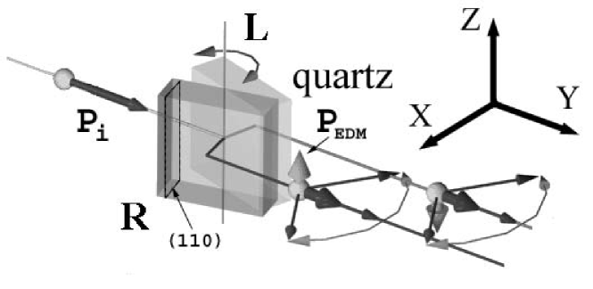
We consider Bragg angles close to , i.e. is almost parallel to . For each of the two Bloch states, a component of the polarization vector perpendicular to builds up in the XY-plane due to the Schwinger precession Eqs. (1,2). These components as well as the electric field have opposite signs for the two Bloch states. The interaction of a finite nEDM with the electric field results in a precession of the polarization vector around , thus creating a component in Z direction, with the same sign for the two Bloch states. is given by [15, 16]:
| (3) |
Here is the nEDM. Rotating the crystal by the angle () changes the sign of and thus that of . This is the experimental signature of a nEDM.
The principal scheme of the method is shown in Fig. 1. We assume that the environmental magnetic field is low enough as to avoid any further spin rotation. For the two crystal positions right (R) and left (L) with the same Bragg angle but with opposite directions of the electric field, the polarizations have opposite signs whereas a residual polarization has the same sign. In the coordinates of Fig. 1, is given by the difference of the Z components of the final polarization vectors for the two crystal positions R and L. High precision of the crystal rotation and “zero” magnetic field conditions are necessary to exclude systematic errors and to select the EDM effect.
¿From Eq. (2) follows that the effect due to the Schwinger interaction does not depend on neutron properties such as the energy, the wavelength or the Bragg angle. It is determined by the property of the crystal and by the fundamental constants only. For a given crystal it is the same for all Bragg angles. In contrast, the EDM effect Eq. (3) depends on the Bragg angle and grows strongly for . Thus, carrying out the measurement for two different Bragg angles gives an additional way to eliminate false effects related to the Schwinger interaction.
3 Experimental set-up
In order to avoid systematic effects, the two crystal positions have to be fully identical. Any gradient of the residual magnetic field or a temperature gradient over the crystal violates this requirement and, finally, can result in a systematic offset on the final polarization which could mimic the searched effect.
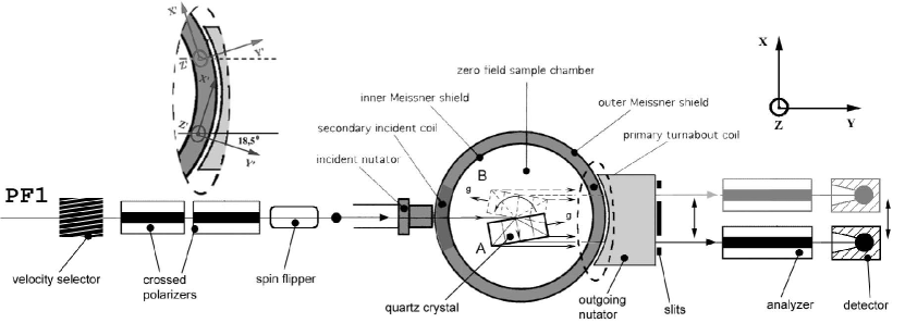
The experimental setup is shown in Fig. 2. It basically consists of the part responsible for the preparation of the beam with the desired neutron wavelength and polarization (neutron velocity selector, polarizer, flipper), the part responsible for the zero-field condition on the sample and spherical polarimetry (Cryopad with nutators [21]), and the analyzer of the final polarization.
The (110) plane (Å) of a quartz crystal was used in the experiment. The size of the crystal was mm3 and its mosaic angular second for the whole body of the crystal.
The experiment was carried out at the end position of the neutron guide H53 (instrument PF1) of the ILL. The guide is connected to the horizontal cold source and provides a capture flux of n/cm2s. The velocity selector served to preselect neutrons with a wavelength of Å and thus reduced the background. To obtain a homogeneous and wavelength-independent incident polarization, two super mirror polarizers were used in crossed geometry [22]. With this set-up, an incident polarization of about 99.5% is expected [22]. The experimental values % for the direct beam and % for the diffracted beams were limited by the analyzing power of the single super mirror analyzer. The neutron spin could be flipped by a resonance flipper.
For spherical polarimetry, the so-called Cryopad-II was used. It consists of two concentric cylindrical Meissner magnetic screens which prevent the penetration of the external field inside the cavity at the height of the beam. -metal screens located above and below Cryopad-II, together with the Meissner screens, assure a reduced magnetic field in the sample chamber. Nutators and superconducting coils are used to select the direction of the incident polarization vector and the component of the outgoing polarization vector that is being analyzed. The residual magnetic field inside the cavity was of the order of a few mG. The cross-section of the beam at the sample was cm2.
The cylindrical geometry of Cryopad leads to a discrepancy of the coordinate systems between the crystal positions L and R (see Fig. 2) and limits the accuracy of the measurement of the polarization vector at about 10 mrad. We estimate that this factor and the residual magnetic field result in a total directional uncertainty of the polarimetry of about 20 mrad. This value agrees qualitatively with the typical precision obtained with this second-generation Cryopad of 35 mrad [21].
Although the superconducting screens are obviously thermically isolated, the air temperature in the center of Cryopad was about 0.5 K higher than that close to the Cryopad walls.
4 Experimental results
The intensity of the diffracted beam for the experimental geometry was about 3-6 n/s for the “grey” polarization direction. It coincides with the result obtained in our previous experiment [19]. The relatively small intensity was mainly limited by the small size of the incident nutator restricting the beam cross-section to cm2. The corresponding statistical sensitivity for the nEDM is ecm per day. This value can be improved by about one order of magnitude by using a more intense neutron beam (for instance the instrument PF1B [20] of the ILL) and increasing the sizes of the beam and of the quartz crystal.
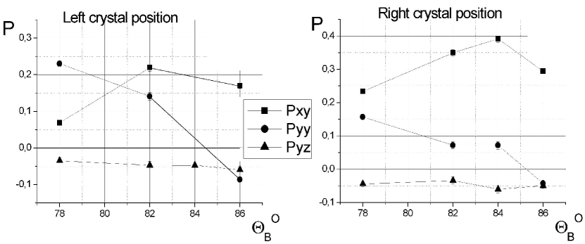
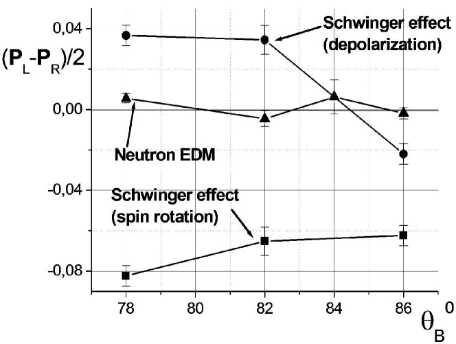
Examples of the measured angular dependences of the elements of the polarization matrix are shown in Fig. 3. Here, indicates the direction of the incident polarization and the analyzed component of the final polarization. The presence of a nEDM would lead to a difference of for the two crystal positions. The observed difference (triangles in the Fig. 4) is consistent with zero and can be used to estimate the nEDM ecm (only statistical error stated). This value, obtained within a few hours of data collection, is 20 times more precise than the result of the crystal diffraction experiment of Shull and Nathans [5]. We did not try to improve the statistical accuracy further since we found large final polarizations , , see Figs. 3 and 4, in contradiction to the expectations.
5 Discussion
To our understanding, the only reason for measuring large elements , of the polarization matrix is a difference between the two Bloch waves amplitudes excited in the crystal.333Note that a nonzero value of the matrix element indicates a neutron spin rotation due to spin-orbit interaction in Laue diffraction. Earlier, such an effect was predicted only for absorbing crystals [10].
A difference of this type can be explained by the Borman effect (different absorptions for the two Bloch waves). However, our estimations for the (110) plane of a quartz crystal show that this mechanism can account for not more than 10% of the observed effect.
A deformation of the crystal could be another possible reason. It is well known that the interaction of neutrons or X-rays with elastically deformed crystals strongly differs from the undeformed case [23, 24, 11]. In our experiment, such a deformation could arise from the temperature gradient of 0.5 K in the Cryopad. The thermal expansion of quartz is . This has to be compared with the Bragg width of the (110) plane of the crystal.
The trajectories of neutrons in a deformed crystal can be described by the so called “Kato forces” [25] that are determined by the value of the crystal deformation. For a constant gradient in the interplanar distance the neutron trajectories inside the crystal are given, see [11, 25]:
| (4) |
where is the so called “Kato mass” ( is the neutron structure factor of the reflection, the volume of the unit cell, and the interplanar distance), the reciprocal lattice vector, and describes the crystal deformation (). The signs in Eq. (4) correspond to the two Bloch waves. Eq. (4) holds for crystal deformations small compared to the Bragg width of the reflection.
The right part of Eq. (4) is proportional to the square of . In our experiment this factor was rather high: (). This results in a very high sensitivity of the neutron trajectories to even small deformations of the crystal.
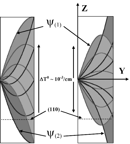
We calculated neutron trajectories in a deformed crystal of cm2 for the temperature gradient K/cm and (). The results are shown in Fig. 5. The left plot corresponds to a constant temperature gradient from one side of the crystal to the other and the right one to a gradient from the center to both sides. The two cases behave differently: For the constant gradient the crystal deformations do not result in different amplitudes for the two Bloch waves at the exit surface. For the gradient from the center to both sides, one Bloch wave ( in Fig. 5) is focused, the other one defocused. Consequently, the amplitudes of the two Bloch waves at the exit surface of the crystal are not equal. The outgoing neutron wave is the superposition of the two Bloch waves where the spin was rotated in opposite directions. Because of their different amplitudes, the depolarization effect described by Eqs. (1,2) is incomplete. For equal amplitudes, the X components of the polarization vectors of the two Bloch waves cancel everywhere (compare Fig. 1). For different amplitudes this is not the case and thus the total polarization vector is rotated in the XY-plane. In our model, it is the new spin rotation effect which is responsible for the high values of the elements and observed in the experiment.
It is important to point out that, although is measured via the Z-component of the final polarization vector, the surviving polarization in the XY-plane can cause an offset to , for example due to a residual magnetic field that turns the polarization toward the Z direction.
On the other hand, the effect permits to manipulate the amplitudes of the Bloch waves by applying a temperature gradient. For the inverse sign of the gradient, for example, is defocused and focused. Manipulating the sign of the temperature gradient is equivalent to changing the sign of the effective electric field seen by the forward diffracted neutrons. By a high temperature gradient one of the Bloch waves can even be fully suppressed.
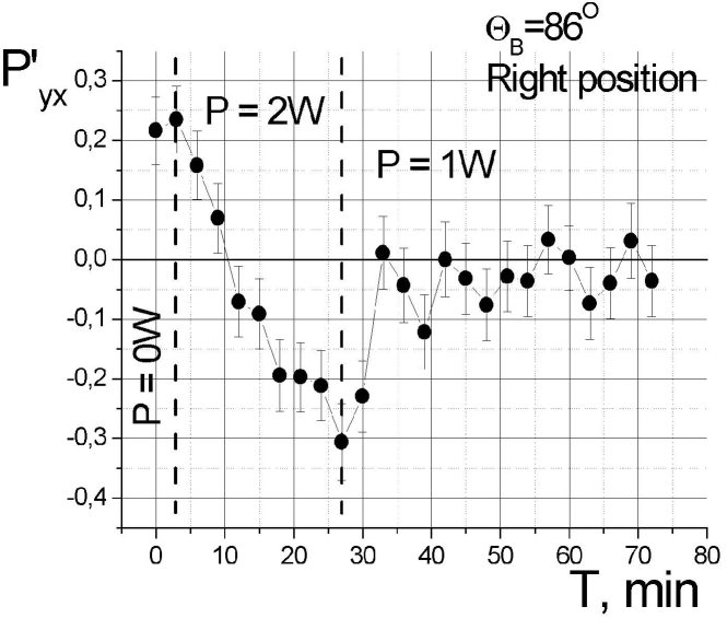
To test our explanation of the observed effect, we intentionally introduced a temperature gradient along the crystal by installing a small electric heater close to one surface of the crystal and measured the spin rotation effect () for different heating powers. The results are shown in Fig. 6: Heating the crystal with an electric power of about 2 W changed the sign of . The process had a relaxation time of the order of half an hour. Reducing the power of the heater to 1 W resulted in the compensation of the spin-rotation effect for the used crystal position. These results are in agreement with our explanation.
6 Conclusions
A prototype experiment to measure the nEDM by Laue diffraction in non-centrosymmetric crystals was carried out. This test allowed us to determine experimentally the statistical sensitivity of the method and to investigate possible systematic errors.
The experiment confirmed our expectation as regards the high statistical sensitivity: already the first run of a few hours resulted in the value ecm which is 20 times more precise than the result of the previous experiment based on crystal diffraction [5]. With a dedicated installation, a statistical precision of the order of ecm per day can be achieved, comparable to the present nEDM experiments with UCNs and the Ramsey resonance method [1, 2].
Beside the statistical precision the most important issue is the question about systematic errors. The main source of systematic errors is a residual magnetic field in the zero-field cavity where the crystal is installed. In our installation we used an old version of Cryopad as cavity, which has a relatively high residual magnetic field of the order of a few mG. This field limits the EDM experiment to a precision of about ecm. We believe that it is possible to build a dedicated spherical polarimeter based on the Cryopad ideas to reach a precision of the EDM experiment of the order of a few times ecm.
The performed experiment also allowed us to discover a new effect: for forward diffraction of polarized neutrons by a non-centrosymmetric crystal of quartz (110 plane) a large () spin-rotation effect induced by a temperature gradient was observed. We identified this effect as a combination of the Schwinger interaction of the neutron spin with the crystal interplanar electric field and the modification of the Bloch waves amplitudes by a temperature induced deformation of the crystal.
The consequences of this new spin-rotation effect are twofold: on the one hand it imposes a limitation on the proposed method to search for a nEDM and requires serious revision of the method, on the other hand it can serve as a new tool to manipulate the sign and the value of the crystal interplanar electric field and, hence, the sign of the nEDM effect. These possibilities open a new road to develop a nEDM experiment exploring the high interplanar field of non-centrosymmetric crystals.
Acknowledgments
The authors would like to thank the personnel of the ILL reactor (Grenoble, France), in particular E. Bourgeat-Lami and S. Pujol, for the technical assistance in the experiment. This work was supported by RFBR (grants No 05-02-16241-a, 03-02-17016-a) and INTAS.
References
- [1] I.S. Altarev, Yu.V. Borisov, N.V. Borovikova, et al., Yad.Fiz. 59 (1996) 1204.
- [2] P.G. Harris, C.A. Baker, K. Green, et al., Phys. Rev. Lett. 82 (1999) 904.
- [3] J.M. Pendlebury, W. Heil, Yu. Sobolev, P.G. Harris, J.D. Richardson, R.J. Baskin, D.D. Doyle, P. Geltenbort, K. Green, M.G.D. van der Grinten, P.S. Iaydjiev, S.N. Ivanov, D.J.R. May, and K.F. Smith, Phys. Rev. A 70 (2004) 032102.
- [4] R. Golub and P.R. Huffman, J. Res. Natl. Inst. Stand. Technol. 110 (2005) 169.
- [5] C.G. Shull and R. Nathans, Phys. Rev. Lett. 19 (1967) 384.
- [6] C.G. Shull, Phys. Rev. Lett. 10 (1963) 297.
- [7] Yu.G. Abov, A.D. Gulko, and P.A. Krupchitsky, Polarized Slow Neutrons, (Atomizdat, Moscow, 1966) 256p. (in Russian).
- [8] M. Forte, J. Phys. G 9 (1983) 745.
- [9] M. Forte and C.M.E. Zeyen, Nucl. Instr. Meth. A284 (1989) 147.
- [10] V.G. Baryshevskii and S.V. Cherepitsa, Phys. Stat. Sol. b128 (1985) 379; Izvestiya Vuzov SSSR, ser. fiz. 8 (1985) 110 (in Russian).
- [11] V.L. Alexeev, E.G. Lapin, E.K. Leushkin, V.L. Rumiantsev, O.I. Sumbaev, and V.V. Fedorov, JETP 94 (1988) 371.
- [12] V.L. Alexeev, V.V. Fedorov, E.G. Lapin, et al., Nucl. Instr. Meth. A 284 (1989) 181; JETP 69 (1989) 1083.
- [13] V.V. Fedorov, V.V. Voronin, and E.G. Lapin, J. Phys. G. 18 (1992) 1133.
- [14] V.V. Fedorov, V.V. Voronin, E.G. Lapin, and O.I. Sumbaev, Tech. Phys. Lett. 21 (1995) 884; Physica B234–236 (1997) 8.
- [15] V.V. Fedorov, E.G. Lapin, S.Yu. Semenikhin, and V.V. Voronin, Physica B 297 (2001) 293.
- [16] V.V. Fedorov and V.V. Voronin, Nucl. Instr. Meth. B 201 (2003) 230.
- [17] V.V. Voronin, E.G. Lapin, S.Yu. Semenikhin, and V.V. Fedorov, JETP Lett. 72 (2000) 308.
- [18] V.V. Voronin, E.G. Lapin, S.Yu. Semenikhin, and V.V. Fedorov, JETP Lett. 71 (2000) 76.
- [19] V.V. Fedorov, E.G. Lapin, E. Lelièvre-Berna, V. Nesvizhevsky, A. Petoukhov, S.Yu. Semenikhin, T. Soldner, F. Tasset, and V.V. Voronin, Nucl. Instr. Meth. B 227 (2004) 11.
- [20] H. Häse, A. Knöpfler, K. Fiederer, U. Schmidt, D. Dubbers, and W. Kaiser, Nucl. Instr. Meth. A 485 (2002) 453.
- [21] F. Tasset, P.J. Brown, E. Lelièvre-Berna, T. Roberts, S. Pujol, J. Allibon, and E. Bourgeat-Lami, Physica B 267-268 (1999) 69.
- [22] M. Kreuz, V. Nesvizhevsky, A. Petoukhov, and T. Soldner, Nucl. Instr. Meth. A 547 (2005) 583.
- [23] Yu.S. Grushko, E.G. Lapin, O.I. Sumbaev, and A.V. Tyunis, JETP 47 (1978) 1185.
- [24] O.I. Sumbaev and E.G. Lapin, JETP 51 (1980) 403.
- [25] N. Kato, J. Phys. Soc. Japan 19 (1964) 971.