XIth International Conference on
Elastic and Diffractive Scattering
Château de Blois, France, May 15 - 20, 2005
Elastic Cross-Section and Luminosity Measurement in ATLAS at LHC
Recently the ATLAS experiment was complemented with a set of ultra-small-angle detectors located in “Roman Pot” inserts at 240m on either side of the interaction point, aiming at the absolute determination of the LHC luminosity by measuring the elastic scattering rate at the Coulomb Nuclear Interference region. Details of the proposed measurement the detector construction and the expected performance as well as the challenges involved are discussed here.
1 Introduction
In March 2004 the ATLAS/LHC collaboration submitted a letter of intent proposing to complement the experiment with ultra-small-angle detectors, in order to measure elastically scattered protons for the primary purpose of absolute determination of the LHC luminosity at the ATLAS interaction point(IP). The detectors will be housed in “Roman Pot” (RP) inserts in the beam pipe located at on either side of the IP and will be able to detect the scattered protons at small enough (mm) distances away from the circulating beam, aiming to reach with the help of special optics, the theoretically well-calculable Coulomb scattering regime. To complete the picture, a second detector called LUCID, based on cylindrical Cerenkov counters is proposed to be installed around the beam pipe close to the interaction point. The LUCID detector is a luminometer, which will be calibrated using the RP detectors and would allow to transfer the luminosity measurement from the low () values used during the special luminosity runs, to the high () values during the main data-taking of ATLAS.
Measuring the small-angle elastic scattering at the Coulomb region is a very attractive and at the same time very a challenging experiment. Other possibilities to accurate estimate and monitor the LHC luminosity with the ATLAS detector will be pursued as well. For example, measuring the and rates or the di-muon pair production rate in double-photon exchange, the relative LHC luminosity could be determined very accurately due to the large statistics available. However it may be difficult to reach an absolute error close to a percent, due to the theoretical uncertainties in the cross-sections and branching ratios involved. Using the machine parameters and optics to estimate the luminosity is another possibility that will be investigated, however the expected error is estimated to be around 10%, dominated by the knowledge of the beam sizes around the interaction region.
An accurate knowledge of the luminosity would be very desirable for a number of physics studies in ATLAS . As an example in the measurement of the Higgs-boson rate as shown in Fig. 2, or in the measurement of cross-sections for processes like production, which, if could be very precisely measured and found different from the SM predictions, could be the sign of interference with new physics!

Traditionally, for hadron colliders, the luminosity as well as the total cross-section has been measured using the so-called “luminosity independent” method. In this approach one needs to measure both the total interaction () and the elastic rates in the forward region. This method was successfully used in previous experiments and is proposed by TOTEM for LHC . Unfortunately the ATLAS detector has limited coverage in the forward region to allow a reasonable measurement of the total inelastic rate. Thus, the only possibility to measure locally (i.e. at ATLAS) the absolute luminosity is to go into even smaller angles and reach the Coulomb Nuclear Interference (CNI) region.
1.1 Elastic Scattering at the Coulomb Nuclear Interference Region
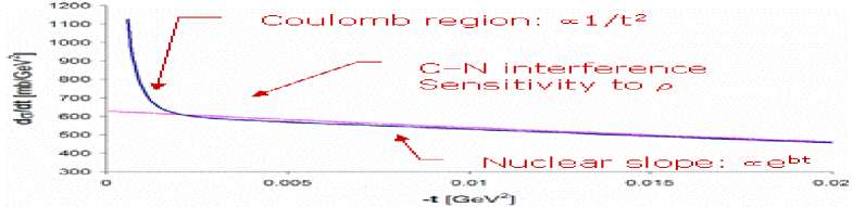
For very small momentum transfer values , , the cross-section becomes sensitive to the well-known electromagnetic amplitude (see Fig 2) as expressed by the formula:
| (1) |
Thus, provided that we are able to probe the CNI region (i.e. the region of values where the strong and the electromagnetic amplitudes become equal) and with the help of the optical theorem, a simple measurement of the elastic rate would allow the determination of the luminosity without measuring the inelastic rate. Moreover, since in practice we will fit the data to Eq 1, the other important parameters such as the -parameter, the total cross-section (), and the nuclear slope will be determined as well. This very powerful technique has been explored previously in the UA4 experiment at the collider with very good results. Our aim is to determine the luminosity within a 2% error and give a competitive measurement on the other parameters.
2 The Experimental Setup
The CNI region at LHC of corresponds to , or for scattering angle . This is a quite challenging angle to measure, about 40 times smaller from that of UA4 at the SPS. Nevertheless, we believe it can be done using special optics and running conditions of the LHC machine, accompanied with very performant edge-less detectors and RP system.
2.1 Optics and Beam Parameters
The typical optics for an elastic scattering experiment is the so-called “parallel to point” optics from the interaction region to the detector location. In such an optics, the betatron oscillation between the interaction point of the elastic collision and the detector position has a 90 degree phase difference in the measuring vertical plane such that all particles scattered at the same angle are focused at the same locus at the detector, independent on their vertex position. In such a case, the measured coordinate at the detector is related to the scattering angle according to while for the momentum transfer we obtain:
| (2) |
Expressing the minimum approach in terms of the beam size at the detector location () we obtain:
| (3) |
From Eq. 2 and 3 the important parameters of the experiment in order to reach the lowest possible value can be extracted: large which means the detectors must be far away from IP, large which means special optics, small emittance and small which means special running conditions and good cleaning efficiency in the machine collimation system in order to keep the beam halo and background rate to affordable levels and allow going close to the beam.
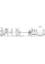
For our experiment, a location in the LHC machine between the Q6 and Q7 quadrupoles at 240 meters from the ATLAS/IP1 was found, where a station of two RP units separated by 3.5 m could be installed as shown in Fig. 3.
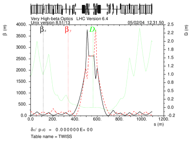
In parallel, a “high-beta” optics solution was found that satisfies the experimental requirements using the existing LHC magnetic elements within the specifications . The optics diagram and the main beam parameters are summarized in Fig. 4. To switch from the standard low-beta optics () to that one, no hardware modifications are required, apart from inverting the polarity for the Q4 quadrupole that could be done remotely.
| Interaction Region |
| Detector Position |
Although the optics would allow reaching the CNI region, the difficulties involved should not be underestimated. The operation scenario envisaged is to have dedicated low intensity runs with only 43 bunches in the machine of protons each, in order to achieve the required transverse emittance of and cleaning efficiency of the collimators. It should be noted that this emittance is the one foreseen for the pilot beam . In recent SPS machine tests, values close to the ones required here were obtained for an LHC structured (25 ns spacing) beam. Of course it remains challenging to preserve the emittance values after injection at LHC, but we hope that after some experience is gained could be feasible. Under these running conditions, the RP detectors could approach the beam as close as , staying in the shadow of the machine collimators. The accidental halo rate expected is about , compared to the expected rate for elastic events of during these special low luminosity () runs.
2.2 Roman Pots and Detectors
The RP units and the detectors have to satisfy similar stringent requirements. The most critical concerns the thickness of the pot window and the detectors to be edge-less in order to reduce the acceptance loss at the inmost side near the beam. Additional requirements for the detectors are for the spacial and angular resolution projecting back to the interaction point from the two RP stations to be both better than . Radiation hardness is not really an issue since the detectors will be used only during the low luminosity runs. The RP unit itself is a high precision mechanical system that should be able to position the two pots (up and down to the beam) with few precision. Moreover, their design must respect all the requirements arising from the LHC machine and due to interferences with the circulating beam (such as RF interference, vacuum, interlock system, etc.). For ATLAS, we plan to use the same RP unit design developed by TOTEM. to whom we are very grateful.
Following a review of various options and possibilities, the choice was made to use scintillating square fibers bunched to form tracker planes as detectors read out using multi-anode PMTs. Ten such planes per coordinate staggered with a pitch of will form a detector assembly, housed in a single RP as shown in Fig. 5. The trigger is provided by a large scintillator plane covering the full detector area. An elastic event will be identified using an left-up(down) right-down(up) coincidence. An important aspect in the design is the two overlap detectors located on each side of the pot in the horizontal plane which using halo tracks would provide a very precise calibration of the gap between the two (up and down) pots and therefore of the absolute scale.
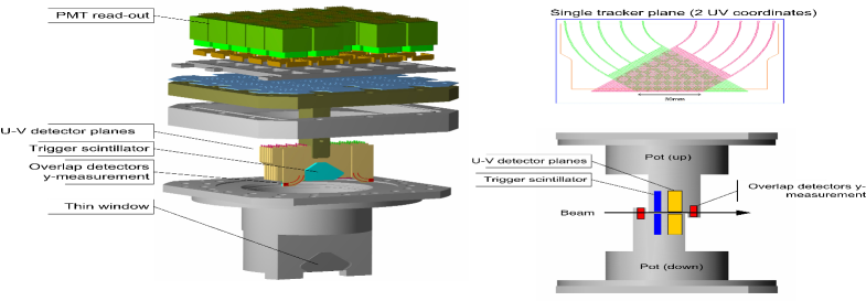

From simulations and first laboratory results, about 3 to 5 photoelectrons are expected per hit, while a resolution of with 95% efficiency was achieved. In Fig. 5 the simulated data on the detector planes are shown. For each event, the scattering angle from the left and right arm with respect to IP was reconstructed and combined. As a preliminary result, using 5 million events, corresponding to about 90 hours of LHC running at a statistical error of about 2% in the luminosity and the other parameters was obtained from a simple fit into the data. In the final analysis however, the fitting procedure would be more complicated taking into account the correlation between the parameters as well as other systematic uncertainties.
3 Future plans
Although our primary goal is to measure the luminosity and the total cross section, further studies in order to extend the measurement of the elastic rate to the maximum values are ongoing. Using the very high-beta optics we hope to reach the CNI region up to values of . Using an intermediate beta optics and short runs with low intensity, the region could be explored, while going to even higher values beyond high luminosity runs with low beta optics would be needed, most likely with different (radiation hard) detectors. Issues like background estimates, trigger and detector performance should be addressed as well but the potential of a very interesting physics program is quite appealing.
Going even further, at a longer time scale, after sufficient experience in dealing with the difficulties associated with working at small distances from the extremely powerful LHC beam is gained, it would allow us to propose a competitive diffractive physics program using possibly additional detectors accessing the full kinematic range of the scattered particle.
References
References
- [1] ATLAS Forward Detectors for Luminosity Measurement and Monitoring, CERN/LHCC/2004-010, 22 March 2004.
- [2] ATLAS Physics TDR, CERN-LHCC/99-14, ATLAS TDR 14 Volume I, Chapter 13.
- [3] UA4 Collaboration, D.Bernard et. al. Phys. Lett. B198 (1987) 583-589.
- [4] “Total Cross Section, Elastic Scattering and Diffraction Dissociation at the LHC”, Technical Proposal, CERN/LHCC-99-7, LHCC/P5, March 1999
- [5] A.Faus-Golfe, M.Haguenauer, J.Velasco, “Luminosity determination using Coulomb scattering at LHC”, EPAC2002 proceedings.
-
[6]
LHC Conceptual design report, CERN/AC/95-05.
R.Assman et.al. “Design and building a collimation system for the high intensity LHC beams”, EPAC 2003.