Presenter: A. Habig (ahabig@umn.edu), usa-habig-A-abs1-he24-poster
The MINOS Detectors
Abstract
The Main Injector Neutrino Oscillation Search (MINOS) experiment’s primary goal is the precision measurement of the neutrino oscillation parameters in the atmospheric neutrino sector. This long-baseline experiment uses Fermilab’s NuMI beam, measured with a Near Detector at Fermilab, and again 735 km later using a Far Detector in the Soudan Mine Underground Lab in northern Minnesota. The detectors are magnetized iron/scintillator calorimeters. The Far Detector has been operational for cosmic ray and atmospheric neutrino data from July of 2003, the Near Detector from September 2004, and the NuMI beam started in early 2005. This poster presents details of the two detectors.
1 Introduction
The MINOS experiment uses two similar detectors to measure the properties of the NuMI neutrino beam over a long baseline, in order to precisely measure the neutrino flavor oscillations seen in atmospheric neutrinos [1]. The beam is created using protons from Fermilab’s Main Injector and is characterized by the Near Detector, located 1 km from the target and 90 m under the surface at Fermilab. The beam then travels northwest 735 km to the Far Detector, located 700 m (2070 mwe) deep in the Soudan Mine Underground Lab in northern Minnesota.
The two detectors are designed to be as similar as possible to minimize the systematic errors resulting from a comparison of the observed neutrino spectra in the two detectors. Both are constructed of vertically hung planes, each plane having a layer of steel (to act as both a neutrino target and a calorimeter) and a layer of plastic scintillator to detect passing charged particles. The steel is also magnetized to allow charge discrimination and momentum determination. The planes are oriented perpendicular to the path of the beam.
2 The Near and Far Detectors
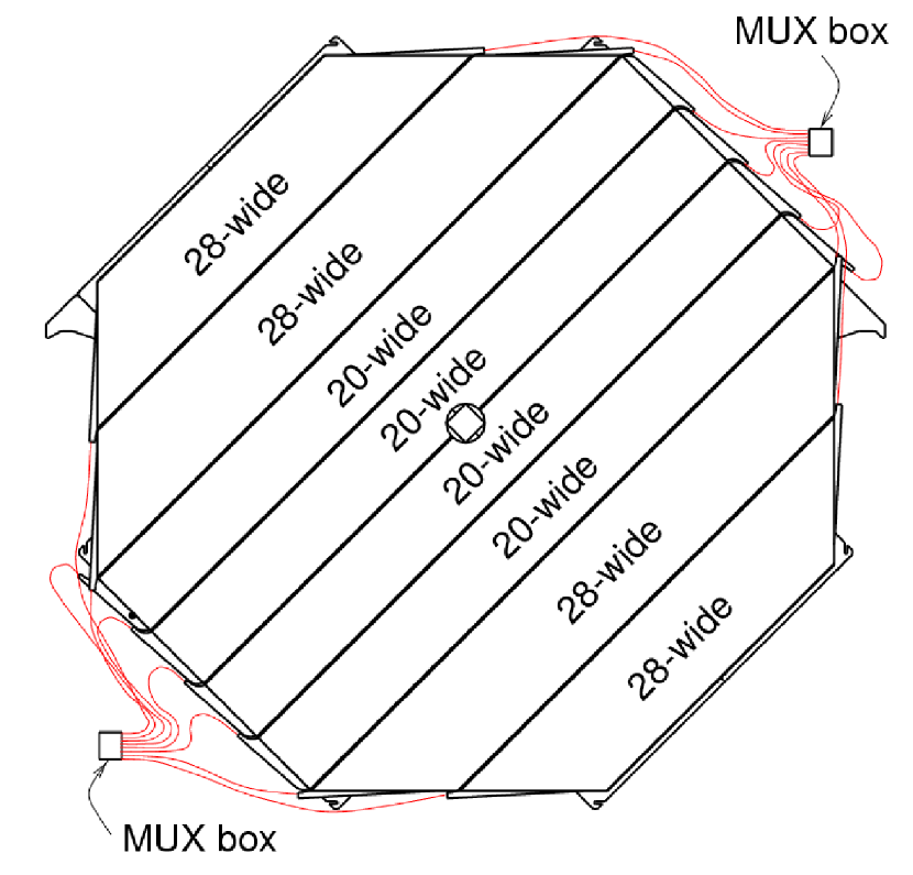
The Far Detector is composed of 486 planes and has a total mass of 5400 tons. It is octagonal in cross section (Fig. 1) with a diameter of 8 m and is divided into two halves or “Supermodules”, each 15 m in depth and separated by a 1.5 m air gap. In addition, a veto shield composed of two layers of scintillator (but no steel) is placed over the top and sides of the Far Detector, to better identify incoming cosmic ray muons that might otherwise enter down the cracks between planes and suddenly appear inside the detector’s fiducial volume.
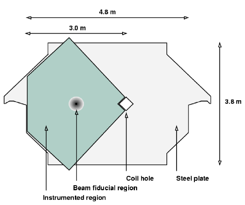
The Near Detector geometry has a 3.8 m4.8 m squashed octagon cross section (Fig. 1). As the beam is centered on the left of the detector and a fiducial region of radius 1 m defined about this point, not all the remaining area is instrumented. There are 282 planes (153 instrumented) for a total mass of 980 tons, spanning a length of 16.6 m. The detector is divided into two regions. The 120 planes in the upstream “forward” region are all instrumented. Every fifth plane has scintillator over most of the plane’s area, with the scintillator on the rest only covering the left side where the beam crosses. This region is used to get a detailed picture of the neutrino interactions occurring in its volume. The 162 planes downstream in the “spectrometer” section are only instrumented every fifth plane (albeit with full scintillator coverage). This region’s purpose is to track the penetrating muons generated by interactions upstream for a momentum determination of these long tracks.
2.1 Steel
The steel planes are 2.54 cm thick AISI 1006 low carbon steel (carbon content between 0.04% and 0.06%), flat to within 0.76 mm. Each detector is magnetized for charge identification and to determine a particle’s momentum by measuring the resulting curvature of its track. The current runs through a coil passing through a 25 cm hole in center of the detector. The Far Detector’s coil provides 15 kA-turns, the Near coil 40 kA-turns, resulting in a toroidal magnetic field in the steel varying between 1–2 T as a function of radius. Knowing how the magnetic field varies in the detector is important to the accuracy of the results obtained from the track curvature. This is accomplished by detailed knowledge of the steel chemistry and careful modeling, cross-checked by measurements of the induced current in induction loops built around each plane of steel.
2.2 Scintillator
The scintillator is composed of cm polystyrene strips extruded to length (up to 8 m in the Far Detector) [2]. The plastic is doped with 1% PPO plus 0.03% POPOP fluors and co-extruded with a white TiO2 layer to contain scintillation light. A groove is cut in this surface down one wide side of the strip and a 1.2 mm Kuraray wavelength shifting (“WLS”) fiber (containing Y-11 at 175ppm) glued into the groove to collect the light. Clear fiber carries the light from the ends of the strips to the phototubes. Also at the strip ends another fiber brings in light from a UV LED. This “Light Injection” system allows the calibration and verification of the complete system by injecting known quantities of light into specific parts of the detector [3]. Strips are laid side-by-side and bundled into “modules”, wrapped with an aluminum skin for light-tightness and ease of handling. Both ends of the Far Detector strips are read out but only one end at the Near. The strips are oriented at from vertical. Alternating planes have strips orthogonal to the last to allow stereo readout.
2.3 Electronics
The light gathered by the clear fibers is carried to “Front End” electronics racks, where it enters a dark box to be optically coupled to a photomultiplier tube (“PMT”). At the Far Detector, light from eight different strip ends is combined onto one pixel of a Hammamatsu R6000-M16 (Far) [4] multi-pixel PMT. M-64 PMTs are used at the Near [5]. There is no multiplexing in the forward region of the Near Detector due to its small size and higher rates, although the spectrometer region is four-way multiplexed.
The phototube signals are digitized by Viking “VA” chips at the Far Detector [6] and FNAL “QIE” chips to meet the faster demands of the high event rate at the Near. In both cases, circuitry is installed to inject known amounts of charge into the digitization circuits for calibration of the digitization. Data are gathered into custom mid-level VME cards for readout by the data acquisition [7]. The unexpectedly high singles rate from light generated in the WLS [8] is mitigated by the imposition of a 2/36 coincidence cut in these mid-level electronics at the Far Detector, but the faster electronics at the Near Detector has no problem with the rates. The data acquisition reads charge and time information (called “digits”) for each phototube signal, combines such data from all parts of the detector, and arranges them into time-ordered “snarls” of data that correspond to physical events. At the time of a beam spill all data is kept. The Near Detector uses the accelerator’s RF signal to gate the low-level electronics, and the far gets GPS beam spill timestamps via the internet and applies this to buffered data in the DAQ’s trigger processing farm. Absent a beam spill, low level singles noise is further suppressed by the application of a software trigger requiring either 4/5 contiguous planes hit (for tracks and large showers) or 6 hits and 1500 ADC counts in any 4 plane window (for small showers). The resulting data is written to disk in the “Root” format [9] for later analysis.
2.4 Operation and Performance
The Far Detector has been fully operational since July 2003, while the Near planes were fully commissioned in August 2004. During the Near Detector installation, as individual planes were commissioned during installation they were added to the data acquisition piecemeal, so a larger set of data exists for partial detector configurations. Cosmic ray muons are seen in both detectors, at rates of 0.5 Hz (Far) and 270 Hz (Near). These muons are used to calibrate the detector and validate the data acquisition and reconstruction, as well as studied in their own right. The seasonal variations in the cosmic ray muon rate has been seen, as has the shadow cast by the Moon in the primary cosmic ray sky. The Far Detector’s veto shield is 97% efficient at rejecting cosmic rays, allowing the detection of atmospheric neutrinos.
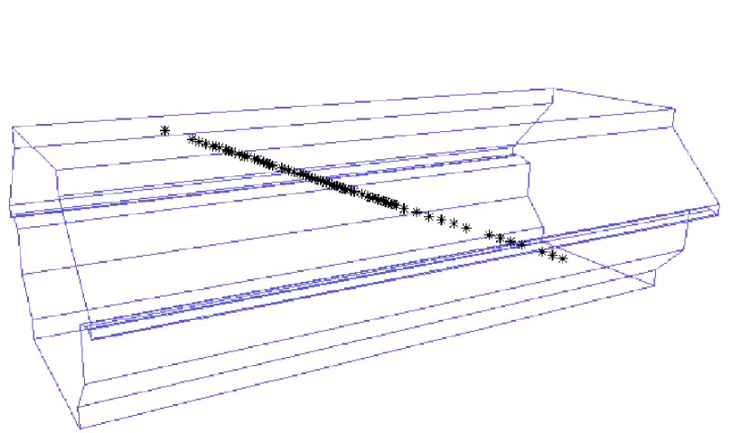
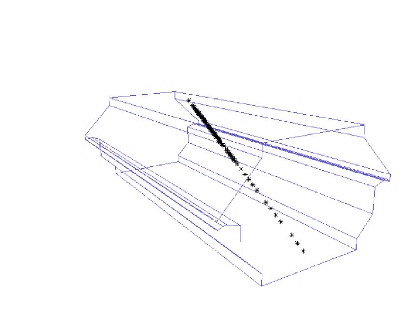
A particle interaction in the detector can be localized to 5.94 cm in the longitudinal direction and 4.1 cm in the transverse direction, allowing muon tracks to be resolved to . The energy resolution for showers is 55%/ for hadrons and 23%/ for electrons. A muon typically yields nine photoelectrons per plane with a timing resolution of 2.4 ns. An example of a cosmic-ray muon track in the Far Detector can be seen in Fig. 2. The Far Detector averages over 95% live time for cosmic rays, and well above 99% for beam data.
The Near Detector sees around 20 neutrino interactions during a typical s long beam spill, during which data is digitized continuously for 18 ms. The resulting data from individual neutrino interactions are “sliced” into discrete events offline, with a granularity of 19 ns. The Far Detector sees far less than one event per spill on average. Neutrino interactions have been observed in the Near Detector since the first beam tests in January 2005, and in the Far Detector since the beam intensity was increased to operational levels in March 2005, and continue to be collected.
3 Conclusions
The Near and Far Detectors of the MINOS long-baseline neutrino oscillation experiment are complete and operational. The two detectors are similar layered iron/scintillator calorimeters to minimize systematic differences. The plastic scintillator is extruded in strips and read out via optical fibers carrying the scintillation light to photomultiplier tubes. Cosmic ray data have been taken in both detectors, starting July 2003 at the Far Detector and August 2004 at the Near. Atmospheric neutrino events have been observed at the Far Detector at a rate of a couple per week [10]. Beam neutrinos have been observed in both detectors, as the beam has been in an operational mode since March of 2005. The MINOS detectors are performing as expected.
4 Acknowledgments
This work was supported by the U.S. Department of Energy, the U.K. Particle Physics and Astronomy Research Council, and the State and University of Minnesota. We gratefully acknowledge the Minnesota Department of Natural Resources for allowing us to use the facilities of the Soudan Underground Mine State Park. This presentation was directly supported by NSF RUI grant #0354848.
References
- [1] Y. Ashie et al., Phys. Rev. D 71, 112005 (2005).
- [2] P. Adamson et al., IEEE Trans. Nucl. Sci. 49, 861 (2002).
- [3] P. Adamson et al., Nucl. Instr. & Meth A 492, 325 (2002)
- [4] K. Lang et al., Nucl. Instr. & Meth A 545, 852 (2005).
- [5] N. Tagg et al., Nucl. Instr. & Meth A 539, 668 (2005).
- [6] J. Oliver et al., IEEE Trans. Nucl. Sci. 51, 2193 (2004).
- [7] A. Belias et al., IEEE Trans. Nucl. Sci. 51, 451 (2004).
- [8] S. Avvakumov et al., Nucl. Instr. & Meth A 545, 145 (2005).
- [9] R. Brun & F. Rademakers, Nucl. Inst. & Meth. A 389, 81 (1997).
- [10] A. Habig et al., these proceedings (2005); K. Ruddick et al., these proceedings (2005).