HERA-B Framework for Online Calibration and Alignment
Abstract
This paper describes the architecture and implementation of the HERA-B framework for online calibration and alignment. At HERA-B the performance of all trigger levels, including the online reconstruction, strongly depends on using the appropriate calibration and alignment constants, which might change during data taking. A system to monitor, recompute and distribute those constants to online processes has been integrated in the data acquisition and trigger systems.
keywords:
Conditions database , calibration , alignment , online reconstruction , PC farmsPACS:
07.05.-t Computers in experimental physics
07.05.Hd Data acquisition: hardware and software
07.05.Bx Computer systems: hardware, operating systems, computer languages and utilities
1 Introduction
It is essential in High Energy Physics experiments, that accurate and consistent detector parameter sets are used at all trigger levels and also in the event reconstruction. Similarly, simulation programs must use detector parameters which are consistent with those used in the trigger and reconstruction to properly simulate the detector and trigger conditions. The detector parameters (such as calibrations, alignments, detector channel maps, resolutions, etc), globally known as detector conditions111The detector conditions will be hereinafter also referred as CnA (Calibration and Alignment) constants, are normally calculated offline in a sporadic manner from monitoring information and event data, and updated in the trigger and reconstruction codes. The bookkeeping of the detector conditions becomes then an important issue.
The HERA-B experiment [1] was designed for the measurement of CP violation in the neutral B-meson system. The data acquisition (DAQ) and trigger systems were designed to cope with more than half a million detector channels, a 40 MHz interaction rate and an extremely low signal to background ratio of . A networked high-bandwidth data acquisition system [2] and a highly selective multi-level trigger [3, 4], with a suppression factor of , were built. Unlike most HEP experiments, HERA-B performs full event reconstruction online.
A novel approach for handling the detector conditions has been followed at HERA-B where a system to monitor, recompute and distribute CnA constants to online clients is integrated into the DAQ and trigger systems. Online updates of the CnA constants help to stabilize trigger performance and online reconstruction as detector conditions vary during data taking. The CnA system is also employed offline during event data reprocessing and Monte Carlo reconstruction. It allows to incorporate offline updates of the CnA constants during the data reprocessing and also ensures that the reconstruction of Monte Carlo simulated events is performed using the same CnA constants employed in the reconstruction of the real data being simulated. This approach is of potential interest to future HEP experiments who are planning sophisticated trigger systems and online event reconstruction.
The architecture, implementation and performance of the CnA system are described in this paper. The motivation for the CnA system and its requirements are summarized in the next section. The system architecture is described in section 3 and its implementation and performance is discussed in section 4. Section 5 describes the offline usage of the CnA system for data reprocessing and Monte Carlo reconstruction.
2 Motivation and requirements
The design and requirements of the online CnA system are driven by the design of the HERA-B detector and the architecture of the DAQ and trigger systems. We therefore begin this section with a description of the relevant aspects of the HERA-B detector, DAQ and trigger systems.
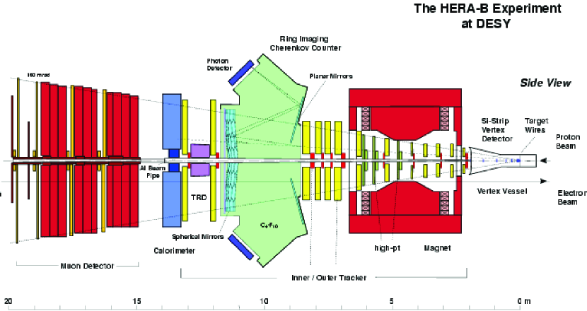
The HERA-B detector is depicted in figure 1. The target wires and the silicon vertex detector (SVD) stations are movable. The target positions change to stabilize the average interaction rate. The SVD stations are also moved towards the beam at the beginning of every fill and retracted at the end to avoid damage during injection. These two subsystems are particularly subject to alignment changes. Although the stepping motors provide sufficient precision (of order 1 micron), alignment corrections are needed relatively often for optimal performance due to thermal and other effects. Similarly, the realignment of the tracking chambers is needed whenever they are moved away from the beam line during accesses to the detector for repairs. Such accesses occur typically at intervals of order one week. The calibration of all detector subsystems is often updated as well. Examples are pedestal following and energy calibration of the electromagnetic calorimeter, the time calibration of the TDC boards of the tracker system, the drift velocity calibration of the tracker system and the maximal value of the Cherenkov angle in the RICH detector which varies with atmospheric pressure, temperature and gas composition. Moreover, the channel status (hot/dead/noisy) maps for all subsystems must be monitored and updated periodically.
The HERA-B DAQ system and its relationship with the trigger levels is sketched in figure 2. The trigger rates, latencies and data volumes of each stage are also shown.
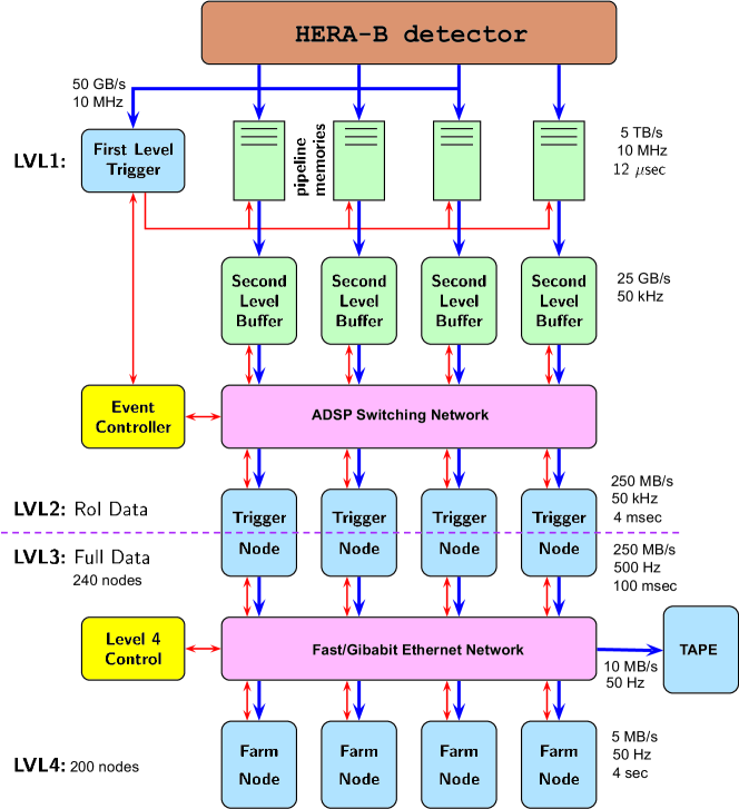
The detector data are read out at the HERA bunch-crossing rate of about 10 MHz and stored in a 128-deep front-end pipelines during the First Level Trigger (FLT) processing. The large input event rate forces the FLT to be entirely built from specialized hardware. The FLT performs hardware tracking to select events with particles decaying into two leptons. The FLT tracking is initiated by lepton candidates in the electromagnetic calorimeter and muon systems. The accepted events are pushed into a distributed system of buffers (Second Level Buffers, -SLB-). The events reside in the SLBs while the Second Level Trigger (SLT) step is being run. The SLT is implemented as a software trigger running in a PC farm of 240 nodes [5].
A switching network provides full connectivity between the SLBs and the SLT nodes. This high bandwidth and low latency switch is built by interconnecting several hundreds of Digital Signal Processors (DSP) between the SLB system and the SLT nodes. The total bandwidth of the DSP switch is above 1 GB/sec. The switch message passing software ensures zero packet loss and, in addition, possesses multicasting capabilities which are used for distributing data sets to all SLT nodes in parallel.
The SLT operates on regions of the detector defined either by FLT track candidates or pretrigger information (Region of Interest -RoI-). The SLT refines the FLT tracks and extrapolates them through the spectrometer magnet, tracks them through the SVD and optionally performs a vertex cut. Tracker and SVD data needed by the SLT are fetched from the SLBs via the DSP switch. Events accepted by the SLT are assembled and, optionally, further processed by the Third Level Trigger (TLT) in the same trigger node. Events passing the TLT are sent via a switched Ethernet network to a second 200-processor PC farm to be fully reconstructed online [6]. Event classification by physics category is performed after the event reconstruction and an additional Fourth Level Trigger (4LT) step can be run at this stage if further reduction of the event rate is required.
The HERA-B trigger system relies on track-finding to an unusual degree. In turn, accurate track-finding and event selection at all trigger levels requires relatively precise knowledge of detector calibration, alignment and detailed detector channel status information all of which can influence both trigger efficiency and trigger rate (and therefore system deadtime). The highly distributed DAQ and trigger systems require a dedicated online system for monitoring and distributing updates of the CnA constants into the trigger processors without incurring significant deadtime.
Running full reconstruction online imposes constraints on the quality of the CnA constants but also allows immediate data analysis and therefore detailed information for data quality monitoring. Given the large data volume collected by the experiment and the large event reconstruction time, offline data reprocessing should be minimized.
3 Architecture
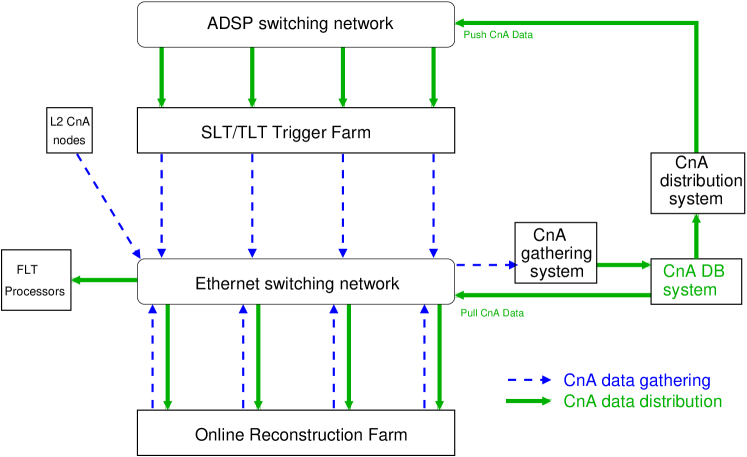
The CnA system provides the online infrastructure for collecting data suitable to align and calibrate the detector, for computing CnA constants and for delivering updated constants to all processes involved in the trigger and the online reconstruction, see figure 3. The CnA system takes care of tagging the set of CnA constants being used at any moment by the DAQ providing an exact history of the set of constants used.
3.1 Data gathering
During the online reconstruction procedure, data for monitoring and calculating detector conditions are collected from the reconstruction processes. In addition, subsystem specific monitors continuously check the raw data and derive channel status maps. To make use of the large number of trigger and reconstruction nodes providing such data in parallel, the CnA architecture relies on a gathering system to collect data in a central place. Gathered data can then be used centrally to compute updated CnA constants which are subsequently stored in the online database system [7].
3.2 CnA distribution
The CnA distribution system delivers updated CnA constants to the trigger and reconstruction processes. This involves distributing large objects to a large number of clients as quickly as possible to minimize deadtime. Two different approaches were followed according to the different latency of the trigger levels and the bandwidth of the DAQ at those stages (see figure 3): a push architecture is best suited for distributing the CnA constants to the FLT and SLT/TLT processes while a pull architecture was chosen for the reconstruction farm.
For the SLT/TLT, trigger latencies are of the order of milliseconds and a fast distribution is required in order not to cause deadtime. Taking advantage of the high speed, reliability and multicasting capabilities of the DSP switch, the CnA data can be synchronously pushed to the trigger processes.
For the online reconstruction farm, several factors favor a pull architecture. The Ethernet switching network of the reconstruction farm has substantially less bandwidth than the DSP switch and would be rapidly saturated if operated under a synchronous push protocol. This would lead to frequent data retransmissions and consequently, to degraded performance. In addition, the Ethernet switches have no support for multicasting so that the same data sets would have to be sequentially pushed into all nodes. Furthermore, the online reconstruction latency is much larger than that of the SLT/TLT and pausing data taking to wait until all events are fully consumed would cause deadtime on the order of seconds. On the other hand, the reconstruction nodes process events asynchronously and independently from each other, and therefore an asynchronous pull protocol would distribute the requests for data over the average reconstruction time and thus make more efficient use of the available bandwidth. Finally, with a pull architecture, a distributed system of fast memory database caches can be implemented to replicate the CnA data and allow for faster uploading and reduction of overall bandwidth requirements.
Since uploading into the reconstruction nodes is asynchronous, the reconstruction processes need to be individually notified when new constants become available. The notification is done through the event data. A data base table (the ”key table”) contains identifiers to all sets of CnA tables which are used by all online processes. The identifier of the current key table (the CnA key) is stamped into events by the SLT process at event assembly time. This index allows an event to be associated with all the calibration and alignment data used in its triggering process and online reconstruction. Whenever updated CnA constants have been distributed to the SLT/TLT nodes or become available for the online reconstruction, a new identifier is stamped in the event data. The reconstruction processes check the CnA identifier and request updated CnA constants when the identifier changes.
For the synchronous distribution of the CnA constants to the FLT and SLT/TLT, a manager process is needed for synchronization during the distribution and also as an intermediary between the CnA producers (processes producing online updated constants) and the consumers (trigger and reconstruction processes). The manager is notified when updated constants are available for distribution. On notification, the manager requests that the FLT/SLT/TLT be paused, supervises the distribution, and requests resumption data taking when the distribution is completed.
The system is quite flexible in that it allows distribution of any kind of information to the trigger processors. This includes FLT and SLT trigger settings as well as geometry and detector calibration data sets. The same distribution protocols used for the on the fly distributions of CnA constants are employed for the initial loading of the constants at DAQ booting time.
3.3 CnA offline usage
The trigger and online reconstruction farms together with the online booting, control, monitoring and online data transmission protocols and processes are used offline for performing data reprocessing and Monte Carlo production during DAQ idle time [8]. The CnA system was also designed for offline use. During data reprocessing, the CnA system allows any online changes of the CnA conditions to be accurately reproduced. Moreover, it provides for use of recalculated sets of CnA constants in place of the online tables, when appropriate. For Monte Carlo reconstruction, the geometry, calibrations and channel maps of the run period being simulated are identified and loaded as well as additional data sets containing detector resolution and efficiency data.
4 Implementation and performance
We describe in this section the implementation of the online calibration and alignment system following the requirements and architecture discussed in the previous sections. Key elements of the system are the data collection and monitor processes (gatherers), the distributed system of database servers and proxies for storage and replication of the constants, and the procedure for distribution to the trigger and reconstruction processes. The CnA framework also includes the software modules for the trigger and reconstruction codes needed to upload the CnA constants.
4.1 Data gathering and computation
Data needed to monitor detector conditions are collected, by gatherers, from the reconstruction processes and from dedicated nodes in the SLT farm which run subsystem-specific monitors. The dedicated SLT nodes receive unbiased events at rates up to several Hz and continuously check the raw event data, updating channel status maps as needed.
As sketched in figure 3, gatherers collect summary data via Ethernet in parallel from all farm nodes. Gatherer processes can work in two distinct modes, either requesting data from the providers or subscribing for the data in the provider nodes which then periodically publish the data to the subscribers. Gatherers can also serve as data providers to other gatherers which subscribe to the provider gatherer for needed data and use the data to update CnA constants. In order to limit the amount of CnA data kept locally in the provider nodes, the CnA data are stored either as histograms or as ring buffers with arbitrary format. A remote histogramming package (RHP[9]) was developed for the data definition and data collection. RHP implements part of the functionality of the CERN HBOOK package [10].
By calling subdetector specific functions, CnA gatherers compute new CnA constants and monitor their evolution over time. If significant changes are produced, the new constants are stored in the distributed database system described in section 4.2, triggering the online on-the-fly distribution as described in section 4.3.
4.2 CnA distributed database system
The storage of updated CnA constants into active database servers triggers online distribution. Upon an update, the CnA database servers propagate update messages notifying the update to the CnA distribution system. Indexed objects (CnA keytables), whose identifiers (CnA key) are stored in the event data, are created automatically by a dedicated CnA database server. The CnA keytable contains CnA metadata, namely the indices of the sets of CnA constants used online during a particular period. The CnA key allows to associate every event with all the CnA constants used in its triggering process and online reconstruction. This bookkeeping is of crucial importance for identifying the correct sets of CnA constants in the event simulation and in the offline event data reprocessing as explained in section 5.
The CnA distributed system of databases consists of active subdetector CnA database servers, a dedicated CnA keytable database server and a distributed system of fast memory database cache servers. The subdetector CnA database servers store the subdetector specific CnA constants and notify the CnA keytable server of any update. The CnA keytable server holds the keytable CnA metadata. After an update message, it generates a new keytable incrementally, i.e., it copies the last keytable and updates the indices of the updated sets of CnA constants. It then publishes to the CnA distribution system the CnA key of the new CnA keytable. The distributed system of memory database caches is used to replicate the CnA constants in order to speed up their distribution to the online reconstruction farm as explained in the next section.
4.3 CnA distribution
As stated before, the distribution procedure of CnA constants is initiated by the storage of new constants into active database servers which then propagate the updates to the CnA keytable database server. This server in turn notifies the CnA distribution system of the existence of updated CnA constants. The distribution procedure is sketched in figure 4.
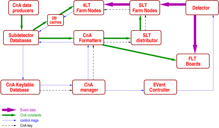
The CnA manager is the process receiving the notifications from the CnA keytable database server. This process is in charge of the control and synchronization of the distribution of the CnA constants. At DAQ booting time, the CnA consumers (trigger and reconstruction processes) subscribe in the CnA manager for updates of particular sets of CnA constants.
The format of the CnA constants as stored in the databases might be different to the format required by the CnA consumers. To centralize the formatting of the constants, to save CPU processing time, and to simplify code in the CnA consumers, CnA formatters were introduced. The formatters are CnA processes that call subdetector specific functions which use one or more raw data base tables to produce the tables which are actually distributed to the consumers. The subscription messages sent by the CnA consumers to the CnA manager identify the associated CnA formatter of the desired set of constants. The CnA formatters fetch any needed CnA tables from the database, make the required formatting and send the formatted constants to the CnA consumers.
The full sequence of the distribution of the CnA constants to the trigger processors is the following: a CnA producer (CnA gatherer) stores updated constants into an active database. The database server informs the CnA keytable server of the update which creates a new keytable with a new CnA key index that is sent to the CnA manager. The manager informs appropriate formatters of the update which then fetch the updated CnA constants from the appropriate database and produce format tables. When the formatting is finished the CnA manager requests the DAQ event controller (EVC) to pause the data taking. The EVC waits until all events in the second level buffers are processed by the SLT nodes before handshaking Cna manager’s request. This way the events already processed by the FLT are processed by the SLT and are stamped with the correct CnA key. In addition, consuming all events in the buffers guarantees that the DSP switch bandwidth will be fully available for the transmission of the CnA constants. The CnA manager then requests the CnA formatter to push the constants into the trigger nodes. The new CnA key is also distributed to the nodes and will be written into the event data of the new events. When the distribution is complete, the CnA manager requests the event controller to resume the data taking.
For distribution to the FLT processors, the FLT CnA formatter sends the constants through Ethernet to a master process running in each of the FLT trigger crates which in turn distributes them in parallel to the trigger boards in the crate. For the distribution into the SLT/TLT farm, the SLT/TLT formatter sends the constants via Ethernet to a dedicated process running in one of the SLT/TLT nodes, the SLT distributor. This process in turn uses the multicasting capabilities of the DSP switch to transmit the constants in parallel to all the 240 trigger nodes. The throughput of the multicasting via the DSP switch is about 1 GB/sec. The constants are synchronously pushed into the trigger nodes under the coordination of the CnA manager. Thanks to the large bandwidth of the DSP switch, the distribution introduces no significant deadtime.
Unlike the distribution to the trigger nodes, where a synchronous distribution is done using a push architecture, the distribution of updated CnA constants to the reconstruction nodes is done asynchronously in each node and using a pull architecture. After any update of the CnA constants, the new CnA key index will end up in the event data. The reconstruction processes upon a change of this index will fetch from the CnA keytable database the new keytable to determine which updated set of constants should be loaded. In order to speed up the loading of the new constants, the reconstruction nodes fetch them via a distributed system of memory database caches. Given the smaller Ethernet bandwidth compared to the DSP switch bandwidth, an asynchronous retrieval of the constants is more efficient.
Exactly the same distribution procedure is applied at DAQ booting time to upload the CnA constants into the trigger and reconstruction processors. At booting time, all the sets of constants appear to be updated and all of them are distributed. Not only detector conditions constants are uploaded following the procedure described above, but also the trigger settings are distributed into the trigger nodes in the same way.
4.4 Performance
Over 60 sets of CnA constants, amounting a total volume of 6.5 MB, are used. At DAQ booting time, they are pushed into the SLT/TLT trigger nodes in 1.5 secs, at a rate of 1 GB/sec (6.5 MB x 240 nodes / 1.5 sec). Upon receiving their first events after run startup, reconstruction nodes fetch the constants at an effective rate of 50 MB/sec (6.5 MB x 200 processes / 25 sec). Note that in this case, 25 seconds is the total time required to completely upload the constants in all the reconstruction processes, but not the deadtime caused since the retrieval is asynchronous and independent in every node so that each node starts processing events as soon as all the constants have been read.
The deadtime caused in the data taking by the distribution of CnA constants to the SLT/TLT nodes is dominated by the time needed for data transmission and multicasting in the DSP switch. The distribution messages containing individual sets of CnA constants are multicasted within the DSP switch. The multicast is based on message copy. The copy of the messages in the first block of the switch dominates the multicast latency. The contribution from the CnA control and distribution protocol is small, of the order of 100 msecs.
The RICH detector calibration and channel status map were updated online at intervals of the order of minutes. ECAL pedestals and tracker channel maps online updates occured at a intervals of the order of hours. Although the online CnA system was fully functional, not all subdector groups developed online monitors or updated CnA constants online due largely to lack of manpower. Calibration and alignment constants for the vertex detector, tracker and muon systems were updated offline by manually updating the index to the relevent tables in the online keytable. The change in the online keytable caused the new constants to be automatically loaded at the next DAQ startup or triggered their distribution if data taking was in progress.
The FLT lookup tables are distributed to the FLT trigger boards at DAQ booting time using the CnA distribution procedure. The large number of these tables and the slow input link to the boards prevents online distributions of updated lookup tables except as part of the startup procedure. Steering parameters for the FLT processes are also distributed via the CnA system.
5 CnA system for offline reprocessing and Monte Carlo reconstruction
As the knowledge of the detectors improves, the reconstruction packages are further developed and improved calibration and alignment constants are made available, the offline reprocessing of the event data becomes necessary. At HERA-B the trigger and online reconstruction farms together with the online booting, control, monitoring and online data transmission protocols and processes are used offline for performing data reprocessing and Monte Carlo reconstruction as described in [8]. Exactly the same CnA distributed database system and CnA data uploading mechanism used for online reconstruction are also employed offline for mass data processing. The only difference between reprocessing and online reconstruction is that the source of the data is not the detector but the recorded raw events archived on tape. This system makes an extremely efficient use of the online computing resources during idle time and shutdown periods of the detector.
As mentioned earlier, the event record includes a tag which links the event with the CnA keytable in the database containing the indices of all the sets of CnA constants used in the online reconstruction of that event. The automatic bookkeeping of the keytables in the database during data taking allows to reproduce the detector calibration and alignment conditions for offline data reprocessing. Sets of constants improved offline are incorporated in the reprocessing by producing a revision of the online keytables. The online keytables are first duplicated in the database with a new revision number and then the keytables corresponding to data taking periods for which updated constants are available are modified with the indices of the updated constants. The offline reconstruction processes make use of a given revision number of the keytables when reprocessing the data.
Monte Carlo event reconstruction should be performed using the reconstruction conditions of the real data one intends to simulate. This is simply achieved by using the keytable (CnA key and CnA revision number) employed in the reconstruction of the real data. For extended data taking periods with several associated keytables, Monte Carlo samples can be reconstructed using those keytables separately, and the events are reweighted according to the relative luminosities of the periods of validity of the different keytables.
6 Summary
In the HERA-B experiment, all trigger levels as well as the online reconstruction critically depend on calibration and alignment constants. In order to keep the trigger performance and the online reconstruction stable under variations of the detector conditions, an online calibration and alignment system was implemented and used. This system monitors the status of the calibration and alignment constants, recomputes them upon significant changes in the calibration or alignment conditions in the detector and if necessary distributes them on the fly to the trigger and reconstruction processors without causing significant deadtime in the data acquisition. The distribution system exploits the high bandwidth and multicasting capabilities of the DSP switch to synchronously push the constants to the SLT/TLT trigger processes with a throughput of 1 GB/s. On the other hand, given the smaller effective network bandwidth of the reconstruction farm and the higher event processing time, the reconstruction processes asynchronously fetch the updated constants from a distributed and replicated database system.
A tag in the event record associates every event with the detector conditions used in the trigger and online reconstruction. This mechanism provides the bookkeeping necessary for offline data reprocessing and Monte Carlo reconstruction. The online CnA distribution system is also used offline for mass data processing.
The integration of the CnA system took place during the HERA-B commissioning runs in 2000/2001. The system was fully operational and routinely working during the 2002-2003 data taking period and is still in use for data reprocessing and Monte Carlo reconstruction.
The upcoming LHC experiments will incorporate PC farms into their DAQ and trigger systems and might find the HERA-B experience concerning the online calibration and alignment system of interest.
7 Acknowledgments
We are grateful to Andreas Gellrich for fruitful discussions. We thank the DAQ subdetector and trigger experts for their work in the integration of the online subsystems into the DAQ CnA framework.
References
- [1] The HERA-B Collaboration, HERA-B, an experiment to study CP violation in the B system using an internal target at the HERA proton ring, DESY-PRC 95/01, 1995.
- [2] M. Dam et al., Nucl. Instr. and Meth. A 525 (2004) 566.
- [3] M. Medinnis, Nucl. Instr. and Meth. A 368 (1995) 161.
- [4] A. Gellrich and M. Medinnis, Nucl. Instr. and Meth. A 408 (1998) 173.
- [5] M. Dam, Second and Third level trigger systems for the hera-b experiment. Proc. of the CHEP’98 conference, Chicago, USA, 1998.
- [6] A. Gellrich, The fourth level trigger online reconstruction farm for HERA-B. Proc. of the CHEP’98 conference, Chicago, USA, 1998.
- [7] A. Amorim et al., The HERA-B database services. Proc. of the CHEP 2000 conference, Padova, Italy, 2000.
- [8] J.M. Hernández et al., Nucl. Instr. and Meth. A 502 (2003) 469.
- [9] U. Schwanke, Trigger and Reconstruction Farms in the HERA-B Experiment and Algorithms for a Third Level Trigger. Ph.D. Thesis, Humboldt-Universität zu Berlin, 2000.
- [10] CERN CN/ASD Group, HBOOK CERN Program Library Y250, CERN, 1998.