Online monitoring system and data management for KamLAND
Abstract
In January 22, 2002, KamLAND started the data-taking. The KamLAND detector is a complicated system which consists of liquid scintillator, buffer oil, spherical balloon and so on. In order to maintain the detector safety, we constructed monitoring system which collect detector status information such as balloon weight, liquid scintillator oil level and so on. In addition, we constructed continuous Rn monitoring system for the 7Be solar neutrino detection. The KamLAND monitoring system consists of various network, LON, 1-Wire, and TCP/IP, and these are indispensable for continuous experimental data acquisition.
1 Introduction
The solar neutrino deficit was a longstanding unsolved problem for almost 30 years. The remaining solutions were limited to only two, LMA and LOW. The LMA parameter was accessible by a laboratory test based on reactor neutrinos with a long-baseline of more than 100 km. KamLAND (Kamioka Liquid scintillator Anti-Neutrino Detector) is such the experiment aiming to examine the oscillation parameters around LMA [1]. The data-taking started in January 22, 2002. The first results of KamLAND came from a study of reactor anti-neutrino oscillations based on an analysis of 162 ton-yr exposure data. KamLAND found fewer electron anti-neutrino events than expected from standard assumptions about the electron anti-neutrino propagation at 99.95% C.L [2]. In the context of two-flavor neutrino oscillations with CPT invariance, all solutions to the solar neutrino problem except for the “LMA”region were excluded. In addition, we searched ’s in the energy range 8.3 MeV E 14.8 MeV. No candidates were found for an expected background of events. This result can be used to obtain a limit on fluxes from any origin [3].
KamLAND detector is complicated system that consists of liquid scintillator, buffer oil and balloon and so on. It is important to take data keeping detector stable. Therefore we constructed KamLAND detector monitoring system. We are planning to take 7Be solar neutrino as a next step. So, we have to remove background and measure it precisely. Therefore we constructed continuous radon(Rn) monitoring network system. In this paper, we explain monitoring system that are maintaining the safety of the KamLAND detector.
2 KamLAND detector
The KamLAND detector (Figure 1) was designed for a low energy neutrino detection with a large volume, 1000 ton liquid scintilator.
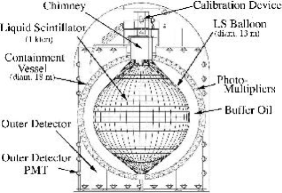
There is 2,700mwe of rock overburden. The cosmic-ray background is reduced to a factor . The core part of the detector is the large volume liquid scintillator(LS). The total volume of the LS is . The liquid scintillator is mixture of 80volume% of dodecane(C12H26) plus 20volume% of pseudocumen(1,2,4-Trimethylbenzene) plus 1.5g/liter of PPO(2,5-Diphenyloxazole:C15H11NO) as a fluor. The direct light output of the LS is more than 50% anthracene equivalent and the transparency is more than 9m for 400nm wavelength light. The liquid scintillator is viewed by 1,325 17-inch-apparture PMTs (Hamamatsu R7250) and 554 20-inch-apparture PMTs which are uniformly distributed in the inner wall of the stainless steel spherical (sss) tank of diameter 9m. The liquid scintillator is contained in a spherical balloon of diameter 13m. The balloon is formed by transparent thin plastic films made of nylon and EVOH (ethylene vynil alchole). The total thickness of the film is 135 and the light transparency is 96% for 400ns wavelength light. The balloon is held in a Kevlar net with the mesh size of about 1m 1m at the equator. The weight of the balloon is measured by load cell at the top of each Kevlar rope. The space between the stainless tank and the balloon is filled by buffer oil (BO), which is a mixture of dodecane and isoparaffin(CnH2n+2, ) oil. The isoparaffin oil has larger specific gravity than dodecane. The specific gravity of the buffer oil is controlled such a way that BO is very slightly lighter than LS by adjusting the dodecane/isoparaffin ratio. The LS and BO were purified to remove 238U, 232Th, 40K and 222Rn before filling in the detector. As a result, for 238U, for 232Th and for 40K were achieved. The region between the sss tank and rock is filled with 3,000 of pure water. 225 20-inch PMTs are submerged in the water and act as cosmic-ray anti-counter. The front-end electronics uses Analog Transient Waveform Digitizer (ATWD) which captures waveforms from each PMT. The trigger makes use of Xilinx FPGA and the global triggers are issued based on number of hit channels (each channels has about 0.3 p.e. threshold). Experimental raw data contains trigger information and digital waveforms. The trigger information contains run number, event number, event time, and number of hits(PMT). The ATWD simultaneously can capture 4 channels of independent signals at 670MHz sample speeds. Then it has sliding capture window with 1.49ns step and 1.49x4ns window, and 128-samples are taken. The ATWD is equipped with a common-ramp parallel Wilkinson 10-bit ADC. In order to reduce dead time, the dual-ATWD ping-pong scheme which requires channel A and B is deployed. Multiple ATWD channels is used to extend the dynamic range; High, Midum, and Low gain. Therefore data size is; . The status of KamLAND detector (balloon weight, temperature, etc.) are monitored by using Slow Control Network. The Slow Control Network consists of LON, CAN and 1-Wire bus. The CAN bus is used to control the VME crates which include ATWDs. The ATWD electronics temperature and electric power consumption and so on are monitored by this network. The LON is monitoring network system of all sensors which covers whole KamLAND area. The 1-Wire bus is additional network system for Rn monitoring. The feature of this network is low cost and easy expansion.
3 LON monitoring system
3.1 Sensors
| Sensor (Number of channel) |
|---|
| Location: Dome area |
| Load cell (Balloon) (44) |
| Temperature (LS, BOI, BOO) (10) |
| Temperature (Anti Water Counter) (4) |
| Temperature (Dome) (1) |
| Atmospheric Pressure (Dome) (1) |
| Oxygen monitor (LS, BOI-Dome) (2) |
| N2 Differential pressure (LS-BOI) (1) |
| N2 Differential pressure (LS-Dome) (1) |
| N2 Differential pressure (BOI-Dome) (1) |
| Anti Counter Water Pressure (2) |
| Location: Purification area |
| LS buffer tank (10m3) oil level (1) |
| LS buffer tank (1m3) oil level (1) |
| LS filter out differential pressure (1) |
| LS filter in differential pressure (1) |
| LS Nitrogen supply tank pressure (1) |
| MO buffer tank (1m3) oil level (1) |
| MO buffer tank (15m3) oil level (1) |
| MO filter out differential pressure (1) |
| MO filter in differential pressure (1) |
| MO Nitrogen supply tank pressure (1) |
| Oxigen monitor (2) |
| Frammable gas monitor (1) |
| LS buffer tank (20m3) oil level (1) |
| BO buffer tank (20m3) oil level (1) |
| Detector Oil Level (LS, BOI, BOO) (3) |
| Detector Bottom LS Pressure (1) |
| Detector Bottom Diff. Press. LS-BO (1) |
| Detector Bottom LS flow rate (1) |
| Detector Bottom BOI flow rate (1) |
| Detector Bottom BOO flow rate (1) |
| Location: Water Purification area |
| Final filter out electric conductivity (1) |
| RO out electric conductivity (1) |
| Temperature (Cooling machine out) (1) |
| LS filter differential pressure (1) |
| MO filter differential pressure (1) |
LS: Liquid Schintilator,
BOI: Buffer Oil (Inner),
BOO: Buffer Oil (Outer),
MO: Mineral Oil (=Buffer Oil).
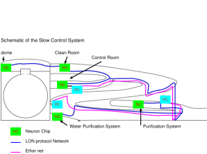
Figure 2 shows whole KamLAND area and location of sensors. Table 1 shows the sensors and locations that are connected in monitoring system.
3.2 Lon Network and Monitoring system
The LON was developed by ECHELON Corporation[4]. LonWorks technology is mainly used by building automation networks. LON network consists of the network modules and Neuron chip ICs required to build intelligent nodes. The control network configuration is installed in them. Each LonWorks node includes local processing and I/O to process input data from sensors and so on. Each node includes the capability to communicate with other nodes because it contains the LONTalk protocol in firmware that are installed Neuron chip or PROM by using LON builder. The LONTalk protocol is a complete 7-layer communications protocol that ensures that nodes can interoperate using an efficient and reliable communications standard.
Each node contains a Neuron chip. The Neuron chip is a transceiver to provide the electrical I/O interface. The sensor-data are gathered via these interface. These data are sent to another node via LON network.
The whole communication length in KamLAND experiment area is about 500 m. Then we used TP/FT-10 Module Transceiver(Echelon) and LW222S LON network cable (Showa densen). The maximum network distances is up to 2700 m (Bus topology twisted pair transceiver), or 500 m (Free topology twisted pair transceiver), we used bus topology. The commuication bit rate is 78 kbps. The TP/FT-10 include Neuron chip TMPN3150(Toshiba), and it need PROM in order to store the commands. We attached AT27C256R (Atmel) on TP/FT-10 board. We made network configuration and each data acquisition program. Then, these code was written on the PROM that were attached at TP/FT-10.
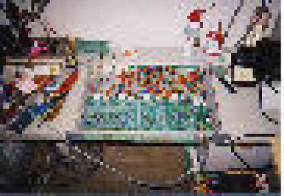
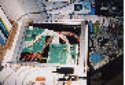
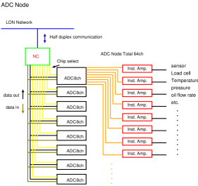
There are two kinds of neuron chip node, ADC data acquisition node and PC interface node. Figure 3 shows ADC data acquisition node and PC interface node. The schematic view of ADC Node is shown in Figure 4. The ADC data acquisition node consists of ADC MAX186(Maxim) and instrumental amplifier AD620(Analog Devices). Almost all sensors have 0-5V or 4-20mA output. These data are converted by these ADCs. The ADC boards have 8ch input interfaces and each channel has these instrumental amplifiers (Max x1000). Each ADC node can connect 8 ADC boards, hence 1 ADC node can read maximum 64 sensors.
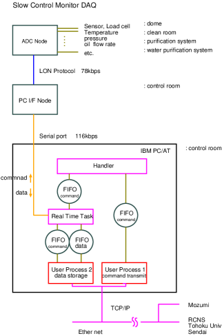
PC interface node gather sensor ADC data via each ADC data acquisition node and send data to PC via RS232c. The bit rate of RS232c is set to 115kbps.
The schematic view of data acquisition is shown in Figure 5. The RT-Linux was used by data acquisition PC. These tasks are connected via FIFOs. User process 1 is human interface of data acquisition system. Real time task is waked up by handler, and this command is sent from user process 1. User process 1 also sends command to each Neuron chip on LON network. When user process 1 sends command to user process 2 in order to store monitor data on file, user process 2 starts storing monitor data. Java GUI interface is deployed for online monitoring of KamLAND area.
4 1-Wire bus Rn monitoring system
We constructed continuous 222Rn monitoring system in the whole KamLAND area. We used Rn monitor (Model 1027) that was manufactured by Sun Nuclear Corporation [5]. In order to gather the 222Rn density data by using the 1-Wire network system, the TTL pulse output read-out interface was attached on Model 1027.
4.1 7Be Solar Neutrino
We are planning to detect the 7Be Solar Neutrino. So, we must reduce radio active background, such as 210Pb, 85Kr and so on. The 210Pb is serious background to detect the 7Be Solar Neutrino and it is daughter nuclei of the 222Rn. The 222Rn density in the air is very high in the kamioka mine, it is KBq/m3. This 222Rn density is much higher than the Rn density that are obtained at the outside of the mine. In addition, the 222Rn density in the mine has seasonal variation. The 222Rn density is high in summer. Therefore, at first, we must monitor 222Rn density in KamLAND area continuously. Then we must reduce 222Rn from KamLAND area.
4.2 1-Wire bus
The 1-Wire is a bus based on a PC communicating digitally over twisted pair cable with the 1-Wire components [6]. The network is defined with an open drain master/slave multidrop architecture that uses a resister pull-up to a nominal 5V supply at the master. The 1-Wire network consists of a bus master (PC) with controlling software, the wiring and 1-Wire devces.
The 1-Wire bus was extended in all KamLAND area and Rn monitors were put at every strategic point.
4.3 Rn monitoring system

Figure 6 shows the Rn monitoring TTL counter node that include counter, temperature and humidity sensors, and ADCs (4ch). The TTL pulse signal from Rn counter is counted by DS2423(Maxim). Then DS2423 send counting data to data acquisition PC. The efficiency of the Rn detection is influenced by humidity. Hence, we measure the humidity by using the HIH-3610(Honeywell). This analog data are converted by DS2438(Maxim) that include ADC and temperature sensors. Then these humidity and temperature data are sent to data acquisition PC via DS2438. Another sensor-analog data are converted by 4ch ADC DS2450(Maxim). Each ADC has instrumentation amprifier AD620(Analog devices), so these sensor data can be read precisely.
These Rn counting nodes were connected by category 6 LAN cable that were applied in all KamLAND area. The electrical power that are consumed by each node is supplied via same network cable. The location of Rn monitors are; Dome area, Control room, N2 purge tower, KamLAND experimental hall entrance, purification room (3), 4th access tunnel, and water purification area. Figure 7 shows the seasonal variation of Rn density in purification area.
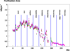
This is due to the direction of the air flow in the kamioka mine.
5 Data management
The monitor data are stored on local PC located in the control room and are sent to sendai via berkeley socket continuously. The data flow rate of monitoring system is about 30MB/day. The experimental raw data flow rate is about 160GB/day. The raw digital waveforms are analyzed and converted to time and charge information. After waveform analysis, the data size reduces to about 1/15, it is about 12GB/day. Then we apply event reconstruction process, the data size reduces to about 1/120, the final data rate is about 100MB/day.
6 Summary
KamLAND experiment started the run from January 22 2002.
Experimental data are accumulated safely by using LON monitoring system.
For the 7Be solar neutrino detection, we must reduce radio active background.
In order to measure Rn density in KamLAND area continuously, we constructed Rn
monitoring network by using 1-Wire network.
Acknowledgements
M. M. sincerely thanks to K.Yamato for suggestion and communication about LON monitoring system. We appreciate supports in the manufacturing process of network by H.Hanada, M.Nakajima, T.Nakajima, T.Takayama and valuable help by K.Eguchi, K.Furuno, H.Ikeda, K.Inoue, Y.Kishimoto, M.Koga, T.Mitsui, K.Nakamura, J.Shirai, A.Suzuki, K.Tamae, E.Yakushev, and other members of KamLAND collaboration.
References
-
[1]
A. Suzuki, Talk at the XVIII International Conference
on Neutrino Physics and Astrophysics, Takayama, Japan, (1998), and
its proceedings.
http://www.awa.tohoku.ac.jp/KamLAND/ - [2] K.Eguchi et al. (KamLAND collaboration), Phys. Rev. Lett. 90 (2003) 021802.
- [3] K.Eguchi et al. (KamLAND collaboration), Phys. Rev. Lett.92 (2004)071301.
-
[4]
http://www.echelon.com
Echelon Corporation, Inc. -
[5]
http://www.sunnuclear.com
Sun nuclear corporation. -
[6]
http://www.dalsemi.com
Maxim Integrated Products, Inc.
Tech Brief 1, MicroLAN Design Guide.