Intense Source of Slow Positrons
Abstract
We describe a novel design for an intense source of slow positrons based on pair production with a beam of electrons from a 10 MeV accelerator hitting a thin target at a low incidence angle. The positrons are collected with a set of coils adapted to the large production angle. The collection system is designed to inject the positrons in a Greaves-Surko trap [1]. Such a source could be the basis for a series of experiments in fundamental and applied research and would also be a prototype source for industrial applications which concern the field of defect characterization in the nanometer scale.
keywords:
positron , positronium , accelerator/linac , defect characterization , 3D molecule imaging , energy storage , gamma ray laser , matter antimatter symmetry , antigravityPACS:
code , code1 Introduction
Phenomena involving positrons are important in many fields of physics, including astrophysics, plasma physics, atomic physics and materials science. In the laboratory, low energy positrons are now being used for many of these applications, including study of electron-positron plasma phenomena [2], atomic and molecular physics [3], antihydrogen formation [4], modeling of astrophysical processes [5], and the characterization of materials [6]. The limitations in these studies are often due to the relative inavailability of suitable positron sources.
Methods to accumulate, cool and manipulate positron plasmas have been developed [1] and used in a recent experiment that created low energy antihydrogen atoms at CERN [4]. Long confinement times (days), increased plasma densities and brightness enhancement are achieved with the rotating electric field technique [7] at temperatures of order 1 meV ( 10 K).
The apparatus presented in this article is designed to produce fluxes of slow positrons of order per second and be stored and/or cooled in a trap. In contrast, radioisotope sources currently in use produce fluxes . Its size is also much smaller than that of a large linac or of a nuclear reactor but could be used as a small facility for interdisciplinary experimental studies with positrons.
Such a source would allow the production of positronium (Ps), hydrogen and antihydrogen in a symmetric way in the same experimental conditions through the set of reactions: , followed by or its antimatter counterpart and the production of ions via or [8].
A novel method to produce a 3D image of molecules with a resolution of few Ångströms has been proposed [9].
Since several years the possibility to create a Bose-Einstein Condensate (BEC) of positronium and to make a 511 KeV gamma ray laser is being studied [10] [11].
These techniques relie or would benefit a lot on the availability of a very intense source of positrons. Moreover a high production rate of slow positrons (exceeding ) and of positronium is being looked for in industrial and research applications, for instance, “Positron Annihilation Spectroscopy” (PAS) [12].
The most commonly used source of positrons is . Such compact sources are well suited for laboratory research, but their maximum activity lies around Bq with a mean lifetime of 2.6 years. There are also some accelerators (100 MeV) partly used for the production of slow positrons which are managed as a facility and a nuclear research reactor in Munich [13].
We propose an alternative intense () source of slow (MeV) positrons based on pair creation through the interaction of a 10 MeV electron beam on a target with an intensity of a few mA. This source was designed to be coupled with a Greaves-Surko trap [14] in order to produce a bright beam of slow positrons (meV to KeV). It may also be used to produce positronium by applying the beam onto a cristal [15].
The pair production cross section increases with energy. However the development of such a setup for university or industrial applications limits the beam energy to 10 MeV because a higher energy would start to activate the environment (legal limit). A dedicated facility would have a size comparable to that of a radioactive source but requires a special building for shielding.
2 Production of positrons
The positrons are produced by the interaction of a flat electron beam with a 50 microns target foil. The angle between the beam plane and the foil is very small, approximatively 3 degrees. The positron kinetic energy spectrum is peaked at 1.2 MeV and extends to 8 MeV.
The first step in the positron capture by the trap is the moderation process. This process involves the slowing down of the positrons, the creation of meta-stable states with collective charge oscillations in the moderator and its re-emission at 1.5 eV. The moderation efficiency decreases with the incident positron kinetic energy and is negligible at a few MeV. Therefore a magnetic collector was designed to separate the positrons from the electrons while preserving the positrons with a kinetic energy below 1 MeV.
2.1 Target
The positron rate is limited by the heating of the target. The target material is tungsten because of its high fusion point (3695K).
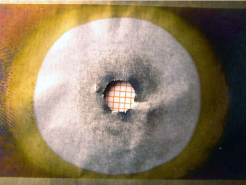
An experimental test was performed with an electron gun used to weld metal pieces. The gun delivered a beam with a diameter around 5mm, i.e. a surface of around 20 (fig 2). The 99.99% purity tungsten target we tested had a thickness of 50 m [16], dimensions of 5 cm x 5 cm and was held with a piece of tungsten surrounding it on three of its sides. The accelerating voltage of the gun was fixed at 40 kV, the intensity was gradually increased until perforation at 20 mA. A 15 mA current does not perforate the target. At 40 kV electrons deposit all their energy in the metal. The target sustains thus a deposit greater than 2 kW/. However a 1 kW/ limit is set on the deposited power as a safety margin.
Even if the temperature is kept well below the fusion point, there will be metal evaporation. Using tables from Langmuir and Jones [17], on the evaporation rate of tungsten filaments for light bulbs under the Joule effect, the target would lose 10% of its mass in one hour at 3100 K, and 24 hours at 2700 K. A simple way of operation would then consist in exchanging the tungsten foil every night. Running at 2700 K means a lower electron intensity and thus a reduction in the rate of a factor 1.7.
2.2 Energy deposit in the target
Simulations were performed with the GEANT 3.21 [19] fortran library. Electrons of 10 MeV/c momentum were generated at an incidence angle of 3 or 90 degrees w.r.t the target plane. For the 3 degree incidence angle, the transverse shape of the beam is a rectangle of 1 mm x 20 mm thus illuminating a square area of 20 mm x 20 mm on the target.
We have computed the energy deposited in targets of various thicknesses with a current of 1 mA (figure 3). For 50 m at 3 degrees or 1mm at 90 degrees, which have the same equivalent thickness 111thickness of target material crossed by electrons supposing straight line propagation (see figure 1)., the deposited energy is respectively 1750 W and 4500 W. This difference is due to the fact that electrons have more possibilities to escape the target when the incidence angle is small. The total path length of an electron and its secondary electrons inside the target is on average 5 times longer at 90 degrees than at 3 degrees for the same equivalent thickness.
The deposited energy increases with equivalent thickness but saturates earlier with very low incidence angle. This allows to deliver a higher intensity for the same illuminated surface. Figure 3 shows the electron current intensity which corresponds to a deposited energy of 1 kW as a function of the equivalent thickness.
2.3 Production rate
The positron rate is given in figure 4. It is of the order of for 1mA electron current and equivalent thicknesses between 1 and 2 mm. These results agree with an independant similar study [20]. The rate of positrons produced with less than 1 MeV of kinetic energy shown in figure 4 is about 1/5 of the total rate.
The limit on the deposited power at 1 kW/, determines the maximum current intensity per of target (see figure 3). The corresponding positron rates are shown in figure 5.
Let us take the example of a 1 target of 50 micron thickness at an incidence of 3 degrees or 0.96 mm equivalent thickness. The deposited power for a 1 mA electron current is 1.75 kW (resp. 4.5 kW) at 3 degrees (resp. 90 degrees). The maximum acceptable current for the limit of 1 kW/, as well as the corresponding positron rate for the maximum current are given in table 1.
| E=10MeV | |||
|---|---|---|---|
| 3 degrees | 0.58 mA | 4.6 | 1.1 |
| 90 degrees | 0.25 mA | 2.5 | 0.55 |
Figure 5 shows that these values stay valid within a factor two for equivalent thicknesses varying from 500 m to 5 mm.
The above quoted production rates were normalized to a target surface of 1 . In the case of the low incidence angle, it is possible to increase the beam intensity while keeping a reasonable transverse extension of the beam, a key parameter to keep a good efficiency for the collection setup described below. In order to illuminate a target of size 1 cm x 1 cm at 3 degrees, the beam is a slit of 1 cm x 0.5 mm.
We will see in the next section on the collection of positrons that it is possible to recover a large fraction of the low momentum positrons with a target size of 2 cm x 2 cm, the beam is then a slit of 2 cm x 1 mm. The beam current needed to illuminate such a target while keeping the constraint of 1 kW/ is then 2.3 mA which produces 4.4 positrons of less than 1 MeV of kinetic energy.
Moving a long strip of 50 thick tungsten in the target plane is a preferred solution to increase the beam current above 2.3 mA.
2.4 Collection
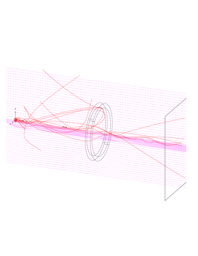
Figure 6 shows the energy distribution of positrons downstream of the target and their angular distribution. The main feature is that the average exit angle with respect to the beam is large, of the order of 50 degrees and even larger for the lowest positron energies.
It is thus necessary to develop a positron collector in order to transport them efficiently at the trap entrance. In order to take advantage of this wide angle of production, a system of coils producing diverging magnetic field lines at the location of the target is used. The magnetic lines are collected by a large diameter coil to form a magnetic bulb.
2.5 Description of the setup
The axis is the axis of the apparatus. The target is a thin rectangular tungsten plate of dimensions 2 cm x 2 cm x 50 m. There are two possible ways to place the beam:
-
•
setup 1: the beam axis coincides with the axis, in which case the target plane makes a 3 degree angle with the axis,
-
•
setup 2: the beam axis makes an angle of 3 degrees with axis , and the target plane contains the axis.
The beam has the shape of a rectangular slit of 2 cm x 1 mm.
In the second configuration, a large part of the beam which traverses the target without much deflection separates from the axis.
| item | x (cm) |
|---|---|
| H1 superconducting coil | -20 |
| target | 0 |
| quad | 11 |
| tungsten dump | 51 |
| H2 large collecting coil | 90 |
| first exit tube coil | 100 |
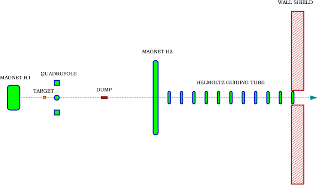
The collection system consists of two main coils of axis (figure 7). The first coil, , has a mean radius of 10 cm, a width along of 5cm and a 5 Tesla field at its center. The target center is placed 20 cm downstream the center of .
The second coil has a 30 cm radius, 20 kA.turns, producing in its center a 420 Gauss field in the same direction as the field at the center of . It is placed 90 cm downstream of the center of the target.
A “recovery” tube consists of a series of flat coils of axis in Helmholtz configuration one with respect to the next, each with a 10 cm diameter and 2 kA.turns. The first of these small coils is placed 10 cm downstream of . The following ones are placed 7 cm from each other constituting a kind of open solenoid.
The beam goes through and hits the target. The particles exiting the target go then through and then through the recovery tube.
A small quadrupole of 10 cm internal radius is placed 11 cm downstream of the target. Its four coils have each a 3 cm radius and 2kA.turns, or a 250 Gauss field at their center. Two of its coils are vertical and the other two are horizontal. It pulls the positrons nearer to the axis.
The field on the axis at the center of the target is of 0.46 Tesla. The radial component at a radius of 1 cm from this axis is 0.28 Tesla.
A dump made of tungsten of 1.6 cm diameter and 5 cm length is placed on the axis at 51 cm downstream of the target.
In order to illuminate the target with a simple slit shaped electron beam, it is enough for setup 1 to include a tilt angle of the target with respect to the vertical in order to correct for the deviation from coil . For setup 2 a beam optics has been designed using octupoles following a method developed by F. Meot [21].
2.6 Collection efficiency
Let us define the collection efficiency (resp.) as the fraction of positrons of a given energy range reaching a plane perpendicular to the axis and located inside the recovery tube at a distance of 2 m from the target, so 1.1 m after , and whose intersection point with this plane is inside a circle of radius 5 cm (resp. 2 cm).
This efficiency depends on the transverse spread, with respect to the axis, of the positron “beam spot”. Figure 9 shows the efficiency variation with the radius of a hypothetical positron source located at the target position. For this calculation, we have generated a uniform spatial distribution of the emitted positrons inside a disk perpendicular to the axis. The angular and energy spectrum corresponding to that of positrons exiting the tungsten target was kept. The efficiency decreases dramatically when the radius of this disk is increased.
On the same figure is also shown the efficiency obtained with a rectangular slit of 2 cm x 1 mm, the axis being contained in the target plane, with or without correcting quadrupole. The same efficiency would be obtained with a disk shape if it had a radius of about 0.4 cm, which could only be obtained with a reduction of the surface of target illuminated by a factor of 0.13 with respect to the 4 plate, and thus a reduction of about an order of magnitude in the rates.
Values for and the final rates of positrons at 2 m from the target are given in table 3.
| rate | rate | |||
|---|---|---|---|---|
| Ec 0 | 20% | 4.2 | 8% | 1.6 |
| Ec 1 MeV | 52% | 2.7 | 20% | 1.1 |
| Ec 600 KeV | 60% | 1.3 | 30% | 0.6 |
2.7 Flux of electrons and photons
The power coming from this device in the space downstream of the coils affects the design of the room shielding, and the coupling to the trap which has a first stage at very low temperature.
Figure 10 shows for setup 1 and 2 the flux of electrons and photons which cross planes perpendicular to the axis, and whose intersection with these planes lie within circles of various radii, as a function of the distance between these planes and the target, for a 1 mA electron beam. The beam is supposed to illuminate the totality of the target surface. At target exit, 7.8 kW are collected. The power deposited in the target is 1.8 kW. The missing 400 W are back scattered.
The power reaching a plane located at 2.5 m from the target is given in detail in table 4 for an electron current of 2.3 mA.
| R = 1 cm | R = 2 cm | R = 3 cm | R = 4 cm | |
|---|---|---|---|---|
| setup 1 | 5 W | 140 W | 450 W | 1.5 kW |
| setup 2 | 10 W | 45 W | 80 W | 110 W |
2.8 Summary
A system of production and collection of MeV positrons has been presented. This setup uses pair creation from electrons hitting a thin tungsten target at a 3 degree incidence angle. The beam comes from a 10 MeV/2.3 mA electron accelerator running in continuous mode. The setup allows to collect more than 5 positrons of less than 600 keV in a 2 cm radius aperture at 2 m from the target. The flux of electrons and photons reaching this aperture is of the order of 50 W.
The system is designed to adapt to a Greaves-Surko trap.
The source itself is made of two sections:
- the 10 MeV accelerator with a dump
- the target and collector system
The best electron source for this application is a Rhodotron, which is commercialized by the IBA [18] firm. This compact machine (about 3 m in diameter) is operated continuously all year long and can reach beam intensities up to 100 mA for food disinfection. Several models are available according to the desired beam intensity. A 10 MeV/2mA model would use 250 kW of power.
Acknowledgements
We wish to express our sincere thanks to all the people from different fields with
whom we had fruitful discussions in order to design this project:
B. Aune,
G. Baldacchino,
J.L. Borne,
P. Debu,
S. Ecklund,
R. Greaves,
M. Jablonka,
P. Lecoeur,
B. Mansoulié,
F. Méot,
J.C. Mialocq,
A.P. Mills,
A. N’Guyen,
J. Sheppard,
M. Spiro,
C. Surko,
G. Vigneron,
and M. Woods.
This technique is subject to a US patent (Serial No: 60/470,883).
References
-
[1]
T.J. Murphy and C.M. Surko, Phys. Rev. A 46 (1992) 5696;
C.M. Surko, S.J. Gilbert and R.G. Greaves, Non-Neutral Plasma Phys. III,
edited by J.J. Bollinger, R.L. Spencer and R.C. Davidson,
(American Institute of Physics, New York), 3-12 (1999);
http://physics.ucsd.edu/research/surkogroup/positron/buffergas.html -
[2]
R.G. Greaves and C.M. Surko, Phys. Plasmas 4 (1997)
1528.
S.J. Gilbert et al., Phys. plasmas 8 (2001) 4982. - [3] M. Charlton, and J.W. Humbertson, Positron Physics, (Cambridge Univ. Press, 2001); C.M. Surko, New Directions in Antimatter Chemistry and Physics, Surko and Gianturco eds, 2001, Kluwer Academic Publishers.
- [4] M. Amoretti et al., Nature, 419 (2002) 456; G. Gabrielse et al., Phys. Lett. B 548 (2002) 140; G. Gabrielse et al., Phys. Rev. Lett. 89, 233401 (2002); G. Gabrielse et al., Phys. Rev. Lett. 89, 213401 (2002).
- [5] K. Iwata, R.G. Greaves and C.M. Surko, Can. J. Phys. 51 (1996) 407.
- [6] P.J. Schultz and K.G. Lynn, Rev. Mod. Phys. 60 (1988) 701.
- [7] R.G. Greaves and C.M. Surko, Phys. Plasmas 8 (2001) 1879.
- [8] Paper in preparation.
- [9] A.P. Mills and P.M. Platzman, New Directions in Antimatter Chemistry and Physics, p. 115, Surko and Gianturco eds, 2001, Kluwer Academic Publishers.
- [10] A.P. Mills, Nucl. Inst. Meth. B 192 (2002) 107.
- [11] E.P. Liang, C.D. Dermer, Opt. Commun. 65 (1988) 419.
- [12] Radiation Physics and Chemistry 68 (2003) 329-680.
-
[13]
C. Hugenschmidt, Nucl. Inst. Meth. B 192 (2002) 97.
FRM-II web site: http://www.frm2.tu-muenchen.de/positron/index.html - [14] R. Greaves et C.M. Surko, Nucl. Inst. Meth. B 192 (2002) 90.
- [15] N. Suzuki et al., Appl. Phys. A 74 (2002) 791-795.
- [16] Goodfellow SARL, 229, rue Solférino, Lille, F-59000, France.
- [17] Handbook of Chemistry and Physics, 10-305, D.R. Lide ed., 73rd edition, 1992, CRC Press.
- [18] IBA (Ion Beam Applications), Chemin du Cyclotron, 3 - 1348 Louvain-la-Neuve, Belgium, http://www.iba-tg.com/root_hq/index.htm
- [19] GEANT 3.21, CERN Library.
- [20] E. Lessner, Proc. 1999 Particle Accelerator Conference, New York, p1967.
- [21] F. Meot and T. Daniel, Nucl. Inst. Meth. A 379 (1996) 196.