The ATLAS Transition Radiation Tracker
Abstract
The Transition Radiation Tracker is a combined tracking and electron identification detector, which is part of the ATLAS Inner Detector at the CERN LHC. Tracking is carried out by drift tubes, while the interleaved radiators produce detectable X-rays when electrons traverse them. The status of the construction and quality control tests will be discussed. The results of beam tests performed on detector prototypes and the expected performance in ATLAS will also be reviewed.
1 Introduction
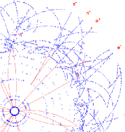
The Transition Radiation Tracker (TRT) is a drift-tube system that, together with silicon-strip and pixel detectors at low radii, constitutes the tracking system of ATLAS, the Inner Detector[1]. It is meant to provide robust tracking information with stand-alone pattern recognition capability in the LHC environment, to enhance the momentum resolution by providing track measurement points up to the solenoid radius and to provide a fast level-2 trigger. By integrating the transition-radiation signature, the TRT also provides stand-alone electron/pion separation (Fig. 1, left).
2 Detector design
The TRT consists of 370,000 cylindrical drift tubes (straws). Each straw (4 mm diameter, made of Kapton® with a conductive coating) acts as a cathode and is kept at high voltage of negative polarity. In the centre of the straw there is a 30 m diameter gold-plated tungsten sense wire. The layers of straws are interleaved with the radiators (polypropylene foils or fibres). The straws are filled with a gas mixture based on xenon (70%) —for good X-ray absorption— with the addition of CO2 (27%) and O2 (3%) to increase the electron drift velocity and for photon-quenching. The Inner Detector lies in a superconducting solenoid magnet generating a 2-T magnetic field parallel to the beam axis over most of its volume.
The TRT has three major modular components: the barrel and two end-caps (Fig. 1, right). The TRT barrel consists of three layers of 32 modules each. The straws are 144 cm long and are parallel to the beam occupying the region between cm and cm, corresponding to a pseudorapidity coverage of 111 denotes the radius in the plane transverse to the beam and the longitudinal position along the beam.. The wires are electrically split in the centre and are read out at both ends, thus reducing the occupancy but doubling the number of electronic channels.
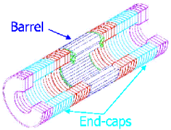
In the end-caps, the straws are radially arranged in 18 units per side called wheels, for a total of 224 layers of straws on each side ( cm). The straws extend between radii of 63 cm and 103 cm, except in the last four wheels (64 layers), where the straws extend between radii of 47 cm and 100 cm, covering thus a pseudorapidity range of .
3 Construction of the TRT
The barrel module construction has taken place in the US (Duke, Hampton and Indiana), whilst the construction of the end-cap wheels is performed in Russia (PNPI and JINR). Assembled wheels and modules arrive at CERN, where they currently undergo various acceptance tests before their integration and installation into the ATLAS Inner Detector. The TRT construction is scheduled to finish in 2005. The progress on the detector construction, the electronics status and the TRT operation in a high-radiation environment are discussed in some detail in Ref. \refciteBari.
3.1 Barrel modules
The assembly of the barrel modules (Fig. 2, left), including wire stringing, has been completed over the last months and, for 40% of them, the gain mapping has been performed before shipping them to CERN. The gas gain is measured at 50 points along each straw using X-rays[3], to identify wires that may be unstable for mechanical reasons (bent straws or misaligned wires); these wires are then removed or replaced. The gain mapping, which lasts 2–3 days, is also used as a signal check and a long-term high voltage test by recording the current draw.
The acceptance tests taking place at CERN include dimensional checks, wire-tension measurements, gas-leak tests and high-voltage conditioning. Gain mapping will also be performed together with possible repairs. In early 2004, module assembly into the barrel support structure will begin and the front-end electronics boards will be installed and commissioned.
3.2 End-cap wheels
Wheel production in Russia is making good progress despite some serious delays with some of the components. Ten 4-plane wheels (out of a total of 80) have been delivered to CERN and undergone acceptance tests, namely dimensional, wire-tension, gas-tightness and high-voltage measurements as well as detailed gain mapping of each straw. The first 8-plane wheel has been prepared and will be used to begin the end-cap stacking procedure.
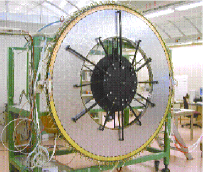
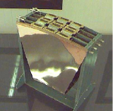
As mentioned above, the gas-gain uniformity at each straw is inspected in an X-ray apparatus (Fig. 2, right). Through the gain scan, various straw characteristics can be assessed, such as the straightness of the straws or the gas-flow uniformity. The measurements, performed over 30,000 straws, have shown that more than 99.9% of all straws are within the specifications.
4 Beam-test performance
4.1 Drift-time measurements
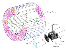
The position accuracy and efficiency[4] of the TRT have been measured in a wheel sector equipped with prototype front-end boards (Fig. 3, left) exposed to a beam of high-energy particles at the CERN SPS. The measured drift time is compared to the extrapolated position of the beam track, determined with high accuracy using a Si-microstrip telescope. The relationship in the straw is obtained in this way (Fig. 3, right) and is used to convert the drift-time measurement into a radial distance from the sense wire. The parameters obtained from the fit are fixed for a given gas gain, electronics signal shape and average energy deposition in the straw, although they may vary somewhat from straw to straw (straw eccentricity, non-circularity).
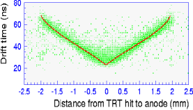
The maximum drift time in the gas is about 40 ns. For a 250-eV threshold, a drift-time resolution of m has been achieved with an efficiency of (the basic straw hit efficiency is around 96%)[2].
4.2 Particle identification
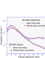
Electron identification[5] makes use of the large energy depositions due to transition radiation (TR). Typical TR photon energy depositions in the TRT are 8–10 keV, while minimum-ionizing particles, such as pions, deposit about 2 keV (Fig. 4, left). The parameter used in electron identification is the number of local energy depositions on the track above a given threshold.
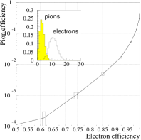
The distributions of the number of energy depositions for pion and electron tracks reconstructed using a wheel sector prototype are shown for a threshold of keV in the top left-hand corner of Fig. 4 (right). In the same figure, the resulting pion efficiency as a function of the chosen electron efficiency is also displayed. For an electron efficiency of 90%, the measured pion efficiency is about 1.2%, i.e. a rejection factor of 75 is achieved against 20-GeV pions in a magnetic field of 0.8 T.
More recent beam-test results on the drift-time measurements and the particle-identification performance of the TRT are discussed in Ref. \refciteBari.
5 Conclusions
The construction of the ATLAS TRT is proceeding well. Significant progress on the quality control of the main components and on the validation tests of the modules and wheels has been made. The assembly of barrel modules is complete and installation into the barrel support structure, to form the complete TRT barrel, will begin in early 2004. The end-cap wheel production, on the other hand, will only be completed in 2005. The quality-control procedures show that the detector will operate initially with less than 1% dead channels.
The beam-test results show that the TRT performance meets the requirements. A drift-time resolution of m with an efficiency of 87% is feasible. For an electron efficiency of 90%, the measured pion efficiency is about 1.2%, i.e. a rejection factor of 75 is obtained against 20-GeV pions.
References
- [1] ATLAS Collaboration, Inner Detector Technical Design Report vol. I & II, CERN/LHCC/97-16 & CERN/LHCC/97-17/(1997).
-
[2]
Proc. TRDs for the 3rd millenium, Bari, Italy,
4–7 Sep. 2003, contributions by the ATLAS TRT collaboration,
to appear in Nucl. Instrum. Meth. A.
https://edms.cern.ch/document/414491/1 - [3] T. Akesson et al., Nucl. Instrum. Meth. A507 (2003) 622.
- [4] Ibid. A367 (1995) 143; A449 (2000) 446; A485 (2002) 298.
- [5] Ibid. A372 (1996) 70; A412 (1998) 200; A474 (2001) 172.