Improving ellipticity detection sensitivity for the Q & A vacuum birefringence experiment
Abstract
Q & A (quantum electrodynamics test and search for axion) experiment was first proposed in 1994 and a 3.5 m high-finesse Fabry-Perot prototype detector extendable to 7 m has been built and tested. We use X-pendulums and automatic control schemes developed by the gravitational-wave detection community for mirror suspension and cavity control. In this paper, we first give an overview of ellipticity detection scheme of Q & A experiment and compare it with other experiments in which Fabry-Perot cavities are also used to multiply the effectiveness of the magnetic field. We then present the displacement spectra of our suspension system and use the data for designing automatic alignment control. Results and experiences gained in the previous test runs have pointed out that the lateral and rotational motion of our suspension system could cause noises and laser off-locks from the Fabry-Perot cavity, and downgrade the ellipticicy detection sensitivity. To fix this problem, i.e., to maintain the alignment between cavity mirrors and incoming laser beam, and to minimize detection noises, we implement an automatic alignment control scheme based on the Ward differential wavefront sensing technique. To improve ellipsometry resolution, we use new polarizers of extinction ratio smaller than .
pacs:
04.80.-y, 12.20.-m, 14.80.Mz, 07.60.Ly, 07.60.Fs, 33.55.Ad1 Introduction
Quantum Electrodynamics (QED) predicts that vacuum is birefringent in a transverse magnetic field. For a B field of 2.5 T, the birefringence index () is . Iacopini and Zavattini [1] proposed to measure the vacuum birefringence in a 10 T magnetic field in the laboratory by a precision determination of the induced ellipticity on a laser beam down to 10-11. The development of ultrahigh-precision technology in the laser-interferometric gravitational-wave detection community prompted our thought of its application to this matter [2]. Cameron et al. [3] performed the first precision measurement of induced ellipticity and polarization rotation of light in vacuum in a magnetic field using a multipass cavity. The result is good to put a limit on the axion-photon coupling; however, it is about 3 orders short from measuring QED birefringence effect.
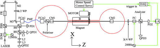
In 1994, 3 experiments were put forward and started for measuring the vacuum berefringence: the PVLAS experiment [4], the Fermilab P-877 experiment [5], and the Q & A experiment [6]. In 1998, we presented a comprehensive comparison of figures of merit of the 3 experiments [6]. PVLAS is now well underway [7]. Fermilab P-877 experiment was terminated in 2000. We have constructed and tested our prototype 3.5 m high-finesse Fabry-Perot inteferometer with ellipsometry [8]. After this first phase, we entered the second phase of improving the detection sensitivity. Figure 1 shows the experimental setup. The laser beam is modulated by a 12 MHz electro-optical modulator (EOM) and injected via a fibre coupler assembly (FCA1), a polarizing maintaining fibre (PMF), the FCA2 on the mirror suspension system, and a Glan-Taylor polarizer to the cavity mirror CM1. The PMF serves as
![[Uncaptioned image]](/html/hep-ex/0308071/assets/x2.png)
Figure 2. Picture of the suspension system.
a simple mode cleaner. The laser is stabilized to the 3.5 m cavity by the Pound-Drever-Hall method. When we achieve the second-phase goals, we will start the third phase of extending the interferometer to 7 m and the magnet to 5 m to measure the vacuum birefringence. A comparison of the PVLAS experiment [7], the new BMV experiment [9] and the Q & A experiment in their developments is compiled in Table 1. With the goals achieved, the expected measurement times to QED vacuum birefringence level for PVLAS experiment, BMV experiment and Q & A experiment are one day, 10 pulses and 2 days respectively.
| Experiment | PVLAS | BMV | Q & A Experiment |
|---|---|---|---|
| Status | Achieved/Goal | Achieved/2-year goal/Goal | Achieved/2-year goal/Goal |
| Wavelength (nm) | 1064 | 1064 | 1064/1064/532 |
| Type of dipole | Rotating | Pulsed | Switching/Rotating |
| magnet | superconducting | permanent | |
| Square of magnetic | 40 | 36/100/625 | 0.72/5.3/6.25 |
| field (T2) | |||
| Length of magnetic | 1 | 0.3/0.3/1.5 | 0.2/0.6/5 |
| field (m) | |||
| Finesse of Fabry- | 120,000 | 50,000/200,000/1,000,000 | 12,000/20,000/100,000 |
| Perot cavity | |||
| Modulation frequency | 1 | 37 | 0.05/10/10 |
| of magnetic field | |||
| (Hz) or 1/duration | |||
| Duration of continuous | 4 hr | 100 msec | 10 days |
| magnet operation | |||
| Magnetic regeneration | hr | 15 min | 10 min |
| time | |||
| Magnetic duty cycle | |||
| Effective magnetic factor | 0.1/0.3/10 | 0.17/3/30 | |
| (T m) | |||
| Sensitivity (radHz-1/2) | / | // | |
| Generated vacuum | // | ||
| birefringent effect (rad) |
In the following, we present the test results of our X-pendulum-double-pendulum suspension system, scheme of automatic alignment control and method of improving ellipsometry. In [10], we will present the magnetic profile of our prototype rotatable permanent magnet and discuss heterodyne detection schemes.
2 Suspension system
Our suspension system for a 3.5 m-cavity mirror consists of an X-pendulum-double-pendulum set mounted on an isolated table inside a vacuum chamber fixed to ground using bellows (Figure 2). X-pendulum, named after the crossed-wire structure used in it, was originally designed by Barton, Kuroda, Tatsumi and Uchiyama [11] of the Institute for Cosmic Ray Research, University of Tokyo, and planned to be installed in TAMA 300 project. We follow closely their design. The X-pendulum has its resonant frequency around 0.28 Hz (Figure 3) and attenuates the horizontal seismic noise in frequency range between 1-20 Hz. The Fabry-Perot cavity mirror is attached to the load table of the X-pendulum via a double pendulum mechanism. To test our suspension system, we have measured the background seismic noise and the relative displacement control noise between two cavity mirrors using heterodyne interferometry. For seismic noise measurement, we simply measured the displacement of the suspended cavity mirror relative to a reference point on the optical table on which the suspension system is mounted; the measured result is the resonant displacement of the suspension itself relative to the seismic motion on the optical bench. For relative displacement between cavity mirrors, a diode-pumped Nd:YAG laser was frequency stabilized to the suspended Fabry-Perot cavity via the Pound-Drever-Hall locking technique. The relative displacement ( 1 Hz) is estimated from the correction signal that drives the PZT of the laser. The spectral density of these displacements are plotted in figure 3, it shows that our suspension system is capable of isolating seismic noise in frequency range between 1-20 Hz. There are many small resonant modes in this frequency band; however, we can avoid these peaks by choosing suitable modulation frequency of the magnetic field. The noise floor at 5-10 Hz is 2-order of magnitude below that at 0.05 Hz.
3 Scheme of automatic alignment system in Q & A experiment
From the test result of our suspension system, we know that the X-pendulum has a large rms amplitude (3-5 m) in 2 horizontal directions of displacement. We need either to tune the frequency of the laser to the cavity length change or to apply force to the cavity mirrors to adjust their positions by a control servo. In the direction parallel to the cavity axis, this has been successfully done in previous test runs [8]. The lateral and rotational motions of the suspension systems misalign the cavity with respect to
![[Uncaptioned image]](/html/hep-ex/0308071/assets/x3.png)
Figure 3. Displacement noises. Curve 1 and 2: Combined displacement of the seismic noises and suspension’s resonant motions in Z and X axes respectively. Curve 3: Relative displacement between CM1 and CM2 in Z axis. Curve 4: Simulation result of the automatic alignment control where curve 2 was used as the noise source.
the incoming laser beam and generate fluctuations of beam intensity and beam spot position. These fluctuations generate noises and degrade the sensitivity in the ellipticity detection. Therefore, for long integration time and high sensitivity measurement, it is necessary to maintain the alignment between cavity mirrors and incoming laser beam. Many techniques have been developed by the Gravitational-Wave Community to maintain this alignment automatically. In our auto-alignment control scheme, we adopt the Ward technique [12]. Beating the rf phase-modulated TEM00 sidebands reflected from the front cavity mirror and the TEM10 of the main band caused by misalignment of cavity mirrors on a split photodiode, we can extract the misalignment signals between these two beams after rf demodulation. In figure 1, QPD1 and QPD2 detect this beat signal. The extracted signals can be linearly combined and fed back to the cavity mirrors via coil-magnet pairs. A simple control servo design and closed-loop-performance simulation have been carried out and show that the transversal motion is reduced to below 10-8 m/Hz1/2 in frequency range between 1-20 Hz (Curve 4 of Figure 3). In this simulation, the measured seismic noise (Curve 2 of Figure 3) were used as the noise source. If necessary, an extra quadrant photodiode will be used to monitor the beam spot position on the analyzer; the position signals can also be fed back to the peizoelectric driven mirror M3 to stabilize beam spot position further and thus decrease the noise in the detected ellipticity.
4 Optical Ellipsometer
Our original optical ellipsometer consists of a Glan-Thomson polarizer and a Glan-Laser analyzer with extinction ratios of the order of 10-7, and a Faraday cell for polarization modulation [8]. We now use two new Glan-Taylor polarizer-analyzer with extinction ratios smaller than 10-8 to upgrade our ellipsometer. We are now performing a tabletop experiment to test the sensitivity of this optical ellipsometry setup.
5 Discussion
In present 2-year goal (Table 1), we hope to increase the sensitivity of ellipsometry by 2 orders of magnitude. The rotating magnet is stable up to 10 Hz (cycle per second) with vacuum birefringence modulation up to 20 Hz. From the measured property of our vibration isolation system, the noises at these frequencies are 2-order smaller than at 0.05 Hz (previous modulation frequency [8]). With the implementation of the automatic alignment control system and the installation of new high-extinction-ratio polarizers, we expect to reach our 2-year goal and to go one step closer to the detection of vacuum birefringence.
For the next phase after this, with 5-fold improvement on optical sensitivity, 5 m rotation permanent magnet,
and interferometer length extended to 7 m, vacuum birefringence would be in our reach.
We thank the National Science Council for supporting this research in part. We are also grateful to G. Cantatore and C. Rizzo for helpful discussions.
References
References
- [1] Iacopini E and Zavattini E 1979 Phys. Lett. 85B 151
- [2] Ni W-T, Tsubono K, Mio N, Narihara K, Chen S-C, King S-K and Pan S-S 1991 Mod. Phys. Lett. A6 3671
- [3] Cameron R, Cantatore G, Melissinos A C, Ruoso G, Semertzidis Y, Halama H J, Lazarus D M, Prodell A G, Nezrick F, Rizzo C and Zavattini E 1993 Phys. Rev. D47 3707
- [4] Pengo R et al1998 Frontier Tests of QED and Physics of the Vacuum 59, ed. E Zavattini et al (Sofia: Heron Press); and references therein
- [5] Nezrick F 1998 Frontier Tests of QED and Physics of the Vacuum 71, ed. E Zavattini et al (Sofia: Heron Press); and references therein
- [6] Ni W-T 1998 Frontier Tests of QED and Physics of the Vacuum 83, ed. E Zavattini et al (Sofia: Heron Press); and references therein
- [7] Zavattini E, Brandi F, Bregant M, Cantatore S, Carusotto S, Della Valle F, Di Domenico G, Gastaldi U, Milotti E, Pengo R, Petrucci G, Polacco E, Ruoso G and Zavattini G 2001 Quantum Electrodynamics and Physics of the Vacuum 77, ed. G Cantatore, AIP Conference Proceedings Vol.564, American Institute of Physics, New York
- [8] Wu J-S, Ni W-T and Chen S-J 2003 Building a 3.5 m Prototype Interferometer for the Q & A Vacuum Birefringence Experiment and High Precision ellipsometry, paper presented at 5th Amaldi Conf. (Tirrenia, July 2003)
- [9] Askenazy S, Billette J, Dupre P, Ganau P, Mackowski J, Marquez J, Pinard L, Portugall O, Ricard D, Rikken G L J A, Rizzo C, Trenec G and Vigue J 2001 Quantum Electrodynamics and Phisics of the Vacuum 115, ed. G Cantatore (AIP)
- [10] Mei H-H, Ni W-T and Chen S-J 2003 A Heterodyne Interferometry Scheme for Detecting the Vacuum Birefringence in in Strong Magnetic Field, to be presented at 5th Amaldi Conf. (Tirrenia, July 2003)
- [11] Tatsumi D, Barton M A, Uchiyama T and Kuroda K 1999 Rev. Sci. Instrum.70 1561; and references therein
- [12] Morrison E, Beers B J, Robertson D I and Ward H 1994 Appl. Opt. 33 5037, 5041