Chapter 1 The AMS-02 Time of Flight System. Final Design
Abstract
The AMS-02 detector is a superconducting magnetic spectrometer that will operate on the International Space Station. The time of flight (TOF) system of AMS-02 is composed by four scintillator planes with 8, 8, 10, 8 counters each, read at both ends by a total of 144 phototubes. This paper describes the new design, the expected performances, and shows preliminary results of the ion beam test carried on at CERN on October 2002.
1. Introduction
The Alpha Magnetic Spectrometer (AMS) is a particle detector that will be installed on the International Space Station (ISS) in 2005 (NASA shuttle flight UF-4.1) to measure Cosmic Ray (CR) fluxes for at least three years.
During the precursor flight aboard of the shuttle Discovery (NASA STS-91 mission, 2–12 June 1998), the test detector AMS-01 was operated for about 180 hours, collecting over one hundred millions CR events [1]. The AMS-02 detector, that will operate on ISS, is described in ref. [2]. Scientific goals of AMS-02 are:
-
•
improved measurement of the antimatter fraction in cosmic rays;
-
•
search for exotic particle annihilation signatures in the proton, electron and -ray spectra over the energy range 1– GeV;
-
•
high statistics measurements of the CR ion spectra below 1 TeV per nucleon.
2. The time of flight system
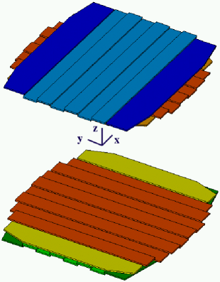
The time of flight (TOF) system of AMS-02, developed in the laboratories of INFN Bologna, will be somewhat different from the TOF system of AMS-01 [3]. The whole system still consists of four plastic scintillator planes (two above and two below the magnet), but with 8, 8, 10, 8 counters each (instead of 14), as shown in figure LABEL:007635-2:fig1 The counters of adjacent planes are orthogonal as in AMS-01, in order to provide a certain granularity at the trigger level, and in each plane they are overlapped by 5 mm. Howewer, the outermost counters of AMS-02 have a trapezoidal shape in order to reduce the weight.
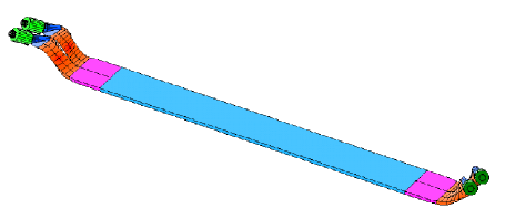
All 1 cm thick scintillators are read at both ends by independently powered photo-multiplier tubes (PMT), connected with transparent light guides, as shown in figure LABEL:007635-2:fig2 Due to the strong residual magnetic field in the PMT zones, the AMS-02 TOF counters adopt the Hamamatsu R5946 phototubes [4] and have curved light guides. The total number of PMT is 144 and the optical contact with the light guides has been realized using soft transparent pads, that also provide a good mechanical coupling. The same method was adopted for AMS-01 and proved to be able to survive both to the launch and to the landing of the shuttle Discovery without any damage to the PMT.
The TOF system has the following essential tasks. First, its signals are used to form the fast trigger (the very first level of the data acquisition chain). Second, the particle time of flight is used to measured the velocity and to distinguish between upward and downward going particles. This is fundamental in order to separate particles from antiparticles. Third, the energy loss measurement is used by the TOF system to send to the trigger box a special flag for ions events, and to provide an independent particle charge measurement.
3. The ion beam test preliminary results
Two AMS-02 TOF counters with cm3 polyvinyltoluene scintillators (Eljen EJ-200, “C1”, and Bicron BC408, “C2”), together with one AMS-01 counter used as reference, were tested at CERN on October 2002 with standard NIM and CAMAC electronics, on the ion beam provided by the SPS facility. The primary Pb beam was directed against 10–30 cm long Be targets, producing secondary particles and nuclei with charge spanning a very wide range: –82. The H8 selection line was tuned to obtain secondaries with , 3/2, 7/4 and 1. For what concerns the scintillators, all primary particles were at their minimum ionization plateau (that is at Lorenz factors 3).


The square root of the anode and dynode signals (in arbitrary units) of the first scintillator during runs 105–114 is shown in figure LABEL:007635-2:peaks The dynode peaks were fitted with gaussians and then the second order Birk’s law:
(where the constants are “adsorbed” by ) was used to obtain the best estimate of the particle atomic number from the measured charge ( is the fitted pedestal position), as shown in the left panel of figure LABEL:007635-2:bt The combined TOF and RICH charge measurement is shown in ref. [5].


Finally, the resolution of the measured time of flight between each pair of counters can be evaluated as function of the particle charge, as shown in the right panel of figure LABEL:007635-2:bt The time resolution improves with increasing charge due to the higher photostatistics, until it reaches a level dominated by the electronic noise [3]. With the standard electronics used at CERN, this level was ps, while the maximum jitter allowed for the AMS-02 TOF front-end boards is 50 ps.
We wish to thank the organizations and individuals acknowledged in ref. [2].
4. References
1. Aguilar M. et al., Physics Reports, vol. 366/6 (2002), 331-404;
2. Gentile S., “The Alpha Magnetic Spectrometer on the International Space Station”, these proceedings;
3. Alvisi D. et al., NIM A 437 (1999) 212-221;
4. Brocco L. et al., Proc. of the 27th ICRC (2001), 2193-2196;
5. Buénerd M., “The AMS RICH detector”, these proceedings.