PAC 2003 Particle Accelerator Conference,
Portland, Oregon (May 12–16) TPPB092
A VERY FAST RAMPING MUON SYNCHROTRON
FOR A NEUTRINO FACTORY
Abstract
A 4600 Hz fast ramping synchrotron is studied as an economical way of accelerating muons from 4 to 20 GeV/c for a neutrino factory. Eddy current losses are minimized by the low machine duty cycle plus thin grain oriented silicon steel laminations and thin copper wires. Combined function magnets with high gradients alternating within single magnets form the lattice. Muon survival is 83%.
Historically synchrotrons have provided economical particle acceleration. Here we explore a very fast ramping muon synchrotron [1] for a neutrino factory [2]. The accelerated muons are stored in a racetrack to produce neutrino beams ( or ). Neutrino oscillations [3] have been observed at experiments [4] such as Homestake, Super–Kamiokande, SNO, and KamLAND. Further exploration using a neutrino factory could reveal CP violation in the lepton sector.
This synchrotron must accelerate muons from 4 to 20 GeV/c with moderate decay loss ( = 2.2 S). Because synchrotron radiation goes as , muons radiate two billion times ( ) less power than electrons for a given ring diameter and lepton energy. Grain oriented silicon steel (3% Si) is used to provide a high magnetic field with a high to minimize magnetic energy () stored in the yoke. Magnetic energy stored in the gap is minimized by reducing its size. Cool muons [5] with low beam emittance allow this. The voltage needed to drive a magnet is . Voltage is minimized by shrinking the volume of stored energy to reduce the inductance, .
Acceleration to 4 GeV/c might feature fixed field dogbone arcs [6] to minimize muon decay loss. Fast ramping synchrotrons [6, 7] might also accelerate cold muons to higher energies for a collider [8].
We form arcs with sequences of combined function cells within continuous long magnets, whose poles are alternately shaped to give focusing gradients of each sign. A cell has been simulated using SYNCH [9]. Gradients alternate from positive 20 T/m gradient (2.24 m long), to zero gradient (.4 m long) to negative 20 T/m gradient (2.24 m) to zero gradient (0.4 m), etc. Details are given in Table 1.
| Cell length | m | 5.28 |
| Combined Dipole length | m | 2.24 |
| Combined Dipole Bcentral | Tesla | 0.9 |
| Combined Dipole Gradient | T/m | 20.2 |
| Pure Dipole Length | m | 0.4 |
| Pure Dipole B | Tesla | 1.8 |
| Momentum | GeV/c | 20 |
| Phase advance/cell | deg | 72 |
| beta max | m | 8.1 |
| Dispersion max | m | 0.392 |
| Normalized Trans. Acceptance | mm rad | 4 |
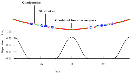
It is proposed to use 5 such arc cells to form an arc segment. These segments are alternated with straight sections containing RF. The phase advance through one arc segment is 5 x 720 = 3600. This being so, dispersion suppression between straights and arcs can be omitted. With no dispersion in the straight sections, the dispersion performs one full oscillation in each arc segment, returning to zero for the next straight as shown in Fig. 1. There will be 18 such arc segments and 18 straight sections, forming 18 superperiods in the ring. Straight sections (22 m) without dispersion are used for superconducting RF, and, in two longer straights (44 m), the injection and extraction. To assure sufficiently low magnetic fields at the cavities, relatively long field free regions are desirable. A straight consisting of two half cells would allow a central gap of 10 m between quadrupoles, and two smaller gaps at the ends. Details are given in Table 2. Matching between the arcs and straights is not yet designed. The total circumference of the ring including combined functions magnets and straight sections adds up to 917 m ().
The RF (see Table 3) must be distributed around the ring to avoid large differences between the beam momentum (which increases in steps at each RF section) and the arc magnetic field (which increases continuously). The amount of RF used is a tradeoff between cost and muon survival. Survival is somewhat insensitive to the fraction of stored energy the beam removes from the RF cavities, because the voltage drop is offset by time dilation.
| Lcell/2 | Lquad | dB/dx | a | |
| 77 0 | 11 m | 1 m | 7.54 T/m | 5.8 cm |
| Bpole | Umag/quad | |||
| 36.6 m | .0195 m | 0.44 T | 3000 J |
| Frequency | 201 | MHz |
|---|---|---|
| Gap | .75 | m |
| Gradient | 15 | MV/m |
| Stored Energy | 900 | Joules |
| Muons per train | ||
| Orbits (4 to 20 GeV/c) | 12 | |
| No. of RF Cavities | 160 | |
| RF Total | 1800 | MV |
| U | 110 | Joules |
| Energy Loading | .082 | |
| Voltage Drop | .041 | |
| Muon Acceleration Time | 37 | sec |
| Muon Survival | .83 |
The muons accelerate from 4 to 20 GeV. If they are extracted at 95% of full field they will be injected at 19% of full field. For acceleration with a plain sine wave, injection occurs at 110 and extraction occurs at 720. So the phase must change by 610 in 37 sec. Thus the sine wave goes through 3600 in 218 sec, giving 4600 Hz.
Estimate the energy stored in each 26.5 m long combined function magnet. The gap is about .14 m wide and has an average height of .06 m. Assume an average field of 1.1 Tesla. The permeability constant, , is . 110 000 Joules. Next given one turn, an LC circuit capacitor, and a 4600 Hz frequency; estimate current, voltage, inductance, and capacitance.
| (1) | |||
| (2) | |||
| (3) | |||
| (4) |
Separate coils might be put around each return yoke to halve the voltage. The stack of SCRs driving each coil might be center tapped to halve the voltage again. Four equally spaced 6 cm coil slots could be created in each side yoke using 6 cm of wider laminations to cut the voltage by five, while leaving the pole faces continuous. 6 kV is easier to insulate than 120 kV. It may be useful to shield [1] or chamfer [10] magnet ends to avoid large eddy currents where the field lines typically do not follow laminations. A DC offset power supply could be useful [1]. Neutrino horn power supplies look promising.
Grain oriented silicon steel is chosen for the return yoke due to its high permeability at high field at noted in Table 4. The skin depth [11], , of a lamination is 160 m from eqn. 5. = resistivity.
| (5) |
Take as a limit on magnetic saturation and hence energy storage in the yoke. Next estimate the fraction of the inductance of the yoke that remains after eddy currents shield the laminations [12]. The lamination thickness, , equals 100 m [13]. L/L0 = = 0.995. So it appears that magnetic fields can penetrate 100 m thick laminations at 4600 Hz. Thicker 175 m thick laminations [14] would be half as costly and can achieve a somewhat higher packing fraction. L/L0( = 175 m) = 0.956.
| Material | 1.0 T | 1.5 T | 1.8 T |
|---|---|---|---|
| 1008 Steel | 3000 | 2000 | 200 |
| Grain Oriented () | 40000 | 30000 | 3000 |
| Grain Oriented () | 4000 | 1000 |
Calculate the resistive energy loss in the copper coils. There are four 5 cm square copper conductors each 5300 cm long. R = So, Eighteen magnets give a total loss of 2340 kW. But the neutrino factory runs at 30 Hz. Thirty half cycles of 109 sec per second gives a duty factor of 300 and a total loss of 8000 watts. Muons are orbited in opposite directions on alternate cycles. If this proves too cumbersome, the duty cycle factor could be lowered to 150. See if .25 mm (30 gauge) wire is usable. From eqn. 6, the skin depth, , of copper at 4600 Hz is 0.97 mm.
| (6) |
Now calculate the dissipation due to eddy currents in this = .25 mm wide conductor, which will consist of transposed strands to reduce this loss [10, 16]. To get an idea, take the maximum B-field during a cycle to be that generated by a 0.025m radius conductor carrying 26000 amps. The eddy current loss in a rectangular conductor made of transposed square wires .25 mm wide (Litz wire [17]) with a perpendicular magnetic field is as follows. Tesla.
| (7) |
| (8) |
Multiply by 18 magnets and divide by a duty factor of 300 to get an eddy current loss in the copper of 170 kW. Stainless steel water cooling tubes will dissipate a similar amount of power [6]. Alloy titanium cooling tubes would dissipate half as much.
Do the eddy current losses [16] in the 100 m thick iron laminations. Use eqn. 7 with a quarter meter square area, a 26.5 m length, and an average field of 1.1 Tesla.
| (9) |
Multiply by 18 magnets and divide by a duty factor of 300 to get an eddy current loss in the iron laminations of 350 kW or 700 watts/m of magnet. So the iron will need some cooling. The ring only ramps 30 time per second, so the hysteresis losses will be low, even more so because of the low coercive force (Hc = 0.1 Oersteds) of grain oriented silicon steel. This value of Hc is eight times less than 1008 low carbon steel.
The low duty cycle of the neutrino factory leads to eddy current losses of less than a megawatt in a 4600 Hz, 917 m circumference ring. Muon survival is 83%. The high permeability of grain oriented silicon steel permits high fields with little energy stored in the yoke. Gradients are switched within dipoles to minimize eddy current losses in ends. Time dilation allows extra orbits with little muon decay at the end of a cooling cycle. This allows one to use more of the stored RF energy. Much of the magnetic field in our lattice is used for focusing rather than bending the muon beam. More muon cooling would lead to less focusing, more bending, and an even smaller ring.
This work was supported by the U. S. DOE and NSF. Many thanks to K. Bourkland, S. Bracker [18], C. Jensen, S. Kahn, H. Pfeffer, G. Rees, Y. Zhao, and M. Zisman.
References
-
[1]
D. J. Summers et al., NuFact 02, hep-ex/0212041;
Berg, Garren, Palmer, Rees, Summers, Zhao, http://www-
mucool.fnal.gov/mcnotes/public/pdf/muc0259/muc0259.pdf. -
[2]
D. Cline and D. Neuffer, AIP Conf. Proc. 68 (1980) 846;
D. Neuffer, IEEE Trans. Nucl. Sci. 28 (1981) 2034;
D. Ayres et al, physics/9911009;
A. Blondel et al., Nucl. Instrum. Meth. A451 (2000) 131;
R. Palmer, C. Johnson, and E. Keil, NIM A451 (2000) 265;
N. Holtkamp, D. Finley, et al, “A feasibility study of a neutrino source based on a muon storage ring,” (2000) FERMILAB-PUB-00-108-E; S. Ozaki, R. Palmer, M. Zisman, J. Gallardo, et al, “Feasibility study II of a muon based neutrino source,” (2001) BNL-52623. -
[3]
V. Barger et al., Phys. Rev. Lett. 45 (1980) 2084;
S. Geer, Phys. Rev. D57 (1998) 6989;
S. M. Bilenky et al., Phys. Rev. D58 (1998) 033001;
V. Barger et al., Phys. Rev. D62 (2000) 073002; 013004;
A. De Rujula et al., Nucl. Phys. B547 (1999) 21;
A. Romanino, Nucl. Phys. B574 (2000) 675;
A. Cervera et al., Nucl. Phys. B579 (2000) 17;
M. Koike and J. Sato, Phys. Rev. D61 (2000) 073012;
K. Kodama et al. (DONUT), Phys. Lett. B504 (2001) 218;
C. Albright, hep-ex/0008064; Waltham, physics/0303116. -
[4]
R. Davis et al. (Homestake), PRL 20 (1968) 1205;
B. T. Cleveland et al., Astrophys. J. 496 (1998) 505;
Y. Fukuda et al. (Super-K), Phys. Rev. Lett. 81 (1998) 1562;
Q. R. Ahmad et al. (SNO), Phys. Rev. Lett. 89 (2002) 011301; 89 (2002) 011302; 87 (2001) 071301;
H. H. Chen, Phys. Rev. Lett. 55 (1985) 1534;
K. Eguchi et al. (KamLAND), PRL 90 (2003) 021802. -
[5]
A. Skrinsky and V. Parkhomchuk, Sov. J. Part. Nucl. 12 (1981) 223; D. Neuffer, Part. Accel. 14 (1983) 75;
R. Fernow and J. Gallardo, Phys. Rev. E52 (1995) 1039;
V. Balbekov and A. Van Ginneken, AIP 441 (1998) 310;
G. Penn and J. S. Wurtele, Phys. Rev. Lett. 85 (2000) 764;
C. Wang and K. Kim, Phys. Rev. Lett. 88 (2002) 184801;
M. M. Alsharo’a et al., hep-ex/0207031. - [6] D. J. Summers, Snowmass 2001, hep-ex/0208010.
- [7] D. Summers, D. Neuffer, Q. S. Shu, and E. Willen, PAC 97, physics/0109002; D. Summers, Snowmass 1996, physics/0108001; Bull. Am. Phys. Soc. 39 (1994) 1818.
-
[8]
D. Neuffer, AIP Conf. Proc. 156 (1987) 201;
D. Cline, NIM A350 (1994) 24; D. Neuffer, ibid., 27;
V. Barger et al., Phys. Rev. Lett. 75 (1995) 1462;
R. Palmer et al., Nucl. Phys. Proc. Suppl. 51A (1996) 61;
R. Raja and A. Tollestrup, Phys. Rev. D58 (1998) 013005;
C. M. Ankenbrandt et al., PRSTAB 2 (1999) 081001;
V. Barger, hep-ph/9803480; M. Berger, hep-ph/0110390. - [9] A. Garren et al., AIP Conf. Proc. 297 (1994) 403.
- [10] N. Marks, “Conventional Magnets – I and II,” CERN Jyväskylä Accelerator School, CERN 94-01, II, 867–911.
- [11] P. Lorrain, D. Corson, and F. Lorrain, “Electromagnetic fields and waves,” 3rd edition (Freeman, 1988) 537– 42.
- [12] K. L. Scott, Proc. Inst. Radio Eng. 18 (1930) 1750 – 64.
- [13] Arnold Eng. (Marengo, IL) http://www.grouparnold.com.
- [14] http://www.aksteel.com/markets/electrical_steels.asp.
- [15] R. Bozorth, “Ferromagnetism,” (Van Nostrand, 1950) 90 –1.
- [16] H. Sasaki, “Magnets for fast–cycling synchrotrons,” Conf. Synchro. Rad. Sources (Indore, 1992) KEK 91-216.
- [17] http://www.mwswire.com/litzmain.htm.
- [18] B. M. Lasker et al., Publ. Astron. Soc. Pac. 85 (1973) 109.