DIRC for a Higher Luminosity B Factory
Abstract
The Dirc, a novel type of Cherenkov ring imaging device, is the primary hadronic particle identification system for the B A B AR detector at the asymmetric B-factory Pep-II at SLAC. It is based on total internal reflection and uses long, rectangular bars made from synthetic fused silica as Cherenkov radiators and light guides. B A B AR began taking data with colliding beams in late spring 1999. This paper describes the challenges for the Dirc in a higher luminosity environment and shows solutions to these challenges.
hep-ex/0304028
SLAC–PUB–9715
October 2002
1 Introduction
The study of CP-violation using hadronic final states of the meson system requires the ability to tag the flavor of one of the mesons via the cascade decay while fully reconstructing the final state of the other over a large region of solid angle and momentum. The momenta of the kaons used for flavor tagging extend up to about , with most of them below . On the other hand, pions from the rare two-body decays must be well-separated from kaons. They have momenta between and with a strong momentum-polar angle correlation between the tracks (higher momenta occur at the more forward angles because of the c.m. system boost)[2]. The Particle Identification (PID) system in B A B AR[3] is located inside the calorimeter volume. Therefore, it should be thin and uniform in terms of radiation lengths (to minimize degradation of the calorimeter energy resolution) and small in the radial dimension to reduce the volume, hence, the cost of the calorimeter.
The PID system being used in B A B AR is a new kind of ring-imaging Cherenkov detector called the Dirc[4] (the acronym Dirc stands for Detection of Internally Reflected Cherenkov light). It is designed to be able to provide excellent separation for all tracks from -meson decays from the pion Cherenkov threshold up to PID below exploits also the measurements in the silicon vertex tracker and drift chamber.
2 Dirc Concept
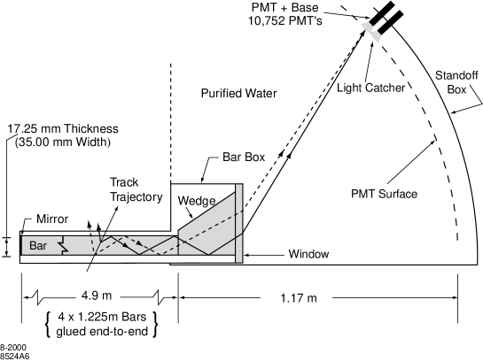
The Dirc is based on the principle that the absolute values of angles are maintained upon reflection from a flat surface. Figure 1 shows a schematic of the Dirc geometry that illustrates the principles of light production, transport, and imaging. The radiator material of the Dirc is synthetic, fused silica in the form of long, thin bars with rectangular cross section. These bars serve both as radiators and as light pipes for the portion of the light trapped in the radiator by total internal reflection. Fused, synthetic silica (Spectrosil[5]) is chosen because of its resistance to ionizing radiation, its long attenuation length, large index of refraction, small chromatic dispersion within the wavelength acceptance of the Dirc, and because it allows an excellent surface polish on the bars[6].
In the following, the variable is used to designate the Cherenkov angle, denotes the azimuthal angle of a Cherenkov photon around the track direction, and represents the mean index of refraction of fused silica () within the wavelength acceptance of the Dirc ( to ). The Cherenkov angle is given by the familiar relation with the velocity of the particle and the velocity of light
For particles with some photons will always lie within the total internal reflection limit, and will be transported to either one or both ends of the bar, depending on the particle incident angle. To avoid instrumenting both ends of the bar with photon detectors, a mirror is placed at the forward end, perpendicular to the bar axis, to reflect incident photons to the backward, instrumented end (see Figure 1).
Once photons arrive at the instrumented end, most of them emerge into a water-filled expansion region, called the standoff box. A fused silica wedge at the exit of the bar reflects photons at large angles relative to the bar axis. It thereby reduces the size of the required detection surface and recovers those photons that would otherwise be lost due to internal reflection at the fused silica/water interface. The photons are detected by an array of densely packed photomultiplier tubes (PMTs)[7, 8], each surrounded by reflecting light catcher cones[9] to capture light which would otherwise miss the active area of the PMT. The PMTs are placed at a distance of about from the end of the bars. The expected Cherenkov light pattern at this surface is essentially a conic section, where the cone opening-angle is the Cherenkov production angle modified by refraction at the exit from the fused silica window.
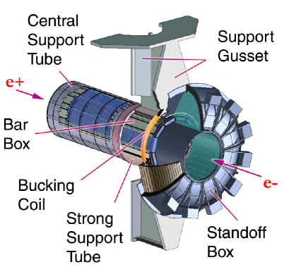
The Dirc bars are arranged in a 12-sided polygonal barrel (see Figure 2). Because of the beam energy asymmetry (at the , Pep-II collides electrons on positrons), particles are produced preferentially forward in the laboratory. To minimize interference with other detector systems in the forward region, the Dirc photon detector is placed at the backward end. The bars are placed into 12 hermetically sealed containers, called bar boxes, made of aluminum-hexcel panels. Dry nitrogen gas flows through each box, and is monitored for humidity to ensure that the bar box to water interface remains sealed. Each bar box contains 12 bars, for a total of 144 bars. Within a bar box the 12 bars are optically isolated by a air gap between neighboring bars, enforced by custom shims made from aluminum foil.
The bars are thick, wide, and long. Each bar is assembled from four pieces that are glued end-to-end; this length is the longest high-quality bar currently obtainable[6, 10]. The bars are supported at intervals by small nylon buttons for optical isolation from the bar box. Each bar has a fused silica wedge glued to it at the readout end. The wedge, made of the same material as the bar, is long with very nearly the same width () as the bars and a trapezoidal profile ( high at bar end, and high at the light exit end). The bottom of the wedge (see Figure 1) has a slight () upward slope to minimize the displacement of the downward reflected image due to the finite bar thickness. The 12 wedges in a bar box are glued to a common thick fused silica window which provides the interface and seal to the purified water in the standoff box.
The standoff box (see Figure 2) is made of stainless steel, consisting of a cone, cylinder, and 12 sectors of PMTs. It contains about of purified water. Water is used to fill this region because it is inexpensive and has an average index of refraction () reasonably close to that of fused silica, thus minimizing the total internal reflection at silica-water interface. Furthermore, its chromaticity index is a close match to that of fused silica, effectively eliminating dispersion at the silica-water interface. The iron gusset supports the standoff box. An iron shield, supplemented by a bucking coil, surrounds the standoff box to reduce the field in the PMT region to below [11].
The PMTs at the rear of the standoff box lie on an approximately toroidal surface. The distance from the end of the bar to the PMTs is Each of the 12 PMT sectors contains 896 PMTs (ETL model 9125[7, 8]) with diameter, in a closely packed array inside the water volume. A double o-ring water seal is made between the PMTs and the vessel wall. The PMTs are installed from the inside of the standoff box and connected via a feed-through to a base mounted outside. The hexagonal light catcher cone is mounted in front of the photocathode of each PMT which results in an effective active surface area light collection fraction of about 90%.
The Dirc occupies of radial space in the central detector volume including supports and construction tolerances with a total of about 19% radiation length thickness at normal incidence. The radiator bars cover a solid angle corresponding to about 94% of the azimuth and 83% of the c.m. polar angle cosine.
3 Dirc Performance
The performance of the Dirc is influenced by two factors. First, information from the PMTs has to be separated into background and signal. Second, the resolution of the signal has to allow for the separation of different particle species.
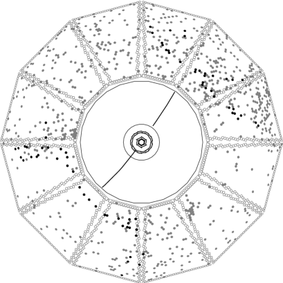
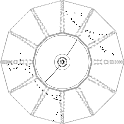
Figure 3 shows a typical di-muon event (). In addition to the signals caused by Cherenkov light from the muon tracks, about 500 background signals can be seen in the readout window centered around the trigger. This background is dominated by low energy photons from the Pep-II machine hitting the standoff box.
The time-to-digital converter (TDC) chip[12] used in the Dirc data readout is designed such that a dead time of about 5% occurs at an input rate of Some care in machine tuning is required to stay under a limit of per tube. To monitor this rate, one PMT in each sector is read out via a scaler. Figure 4 shows the maximum scaler rate as a function of the Pep-II luminosity during data taking in 2000 and 2001. In March 2000 the accelerator operated at a peak luminosity of . Figure 4(a) shows, at a value corresponding to only one third of the design luminosity, the PMT rates reached a level that caused noticeable dead times. Due to those findings, lead shielding was installed in the summer of 2000 around the beam line components near the backward end-cap. Initially, localized shielding was added in the form of lead bricks which were stacked around the beam pipe and in front of a large quadrupole. This shielding significantly improved the background situation so that noticeable TDC dead times were reached only at (Figure 4(b)). During the shutdown in January 2001, the localized lead brick shielding was replaced by an engineered, homogeneous lead shielding of to thickness covering the inside radius of the standoff box and is easily removable to facilitate access to the central detector and beam line components. As is shown in figure 4(c), the maximum scaler rates at luminosities of are well below the level that would cause TDC inefficiencies.

During the shutdown following the 2001-2002 run, we plan to replace the TDCs with a faster version with deeper buffering that is designed to have a deadtime of less than 5% at input rate, suitable for luminosities of at least
The Dirc is intrinsically a three-dimensional imaging device. Photons are focused onto the phototube detection surface via a “pinhole” defined by the exit aperture of the bar, so that the photon propagation angles and can be measured in two-dimensional space, where (bar width) and (bar thickness) are the directions transverse to the bar axis. The travel time of the photon down the bar is also related to the photon propagation angle () with respect to the bar axis. Imaging in the Dirc occurs in all three of these dimensions, by recording the time of the PMT signal. As the track position and angles are known from the tracking system, these three angles can be used to determine the two angles (). This over-constraint on the angles is particularly useful in dealing with ambiguities and high background rates.
The single photon resolution can be calculated from the geometrical, the chromatic and the transport term. The geometrical uncertainty is, for the pinhole optics of the Dirc, given by the standoff box size, the bar and the PMT size. With it is the single biggest contribution to the single photon resolution. The chromatic uncertainty originates from the fact that the photons are produced with different wavelengths and, therefore, have different cone opening angles Using the range in photon wavelength accepted by the PMTs, the chromatic effect contributes to the resolution with The final uncertainty comes from imperfections of the bars and the glue joints. This transport term is approximately to
Combining the three contributions, a single photon resolution of is expected for the Dirc. Figure 5 shows the single photon angular resolution obtained from di-muon events. There is a broad background of less than 10% relative height under the peak that originates mostly from track-associated sources, such as rays, reflections off the glue-fused silica boundaries, and combinatorial background[13]. The width of the peak translates to a resolution of about in good agreement with the expected value.

The resolution on the track Cherenkov angle is defined by a correlated term and the single photon resolution which scales with the number of photoelectrons:
| (1) |
where is the number of photons detected per track.
The number of photoelectrons varies between 16 for small values of at the center of the barrel and 60 at large values of as is shown in Figure 6. This variation is well reproduced by Monte Carlo simulation and can be understood from the geometry of the Dirc. The number of Cherenkov photons varies with the path length of the track in the radiator, it is smallest at perpendicular incidence at the center and increases towards the ends of the bars. In addition, the fraction of photons trapped by total internal reflection rises with larger values of This increase in the number of photons for forward going tracks is a good match to the increase in performance required at larger momentum.

With the present alignment, the track Cherenkov angle resolution for di-muon events is shown in Figure 7. The width of the fitted Gaussian distribution is compared to the design goal of

The measured time resolution is close to the intrinsic transit time spread of the PMTs. This resolution is used to efficiently distinguish background from signal photons but is not sufficient to improve the Cherenkov angle resolution.
Figure 8 shows an example of the use of the Dirc for particle identification. The invariant mass spectra are shown with and without the use of the Dirc for kaon identification. The peak corresponds to the decay of the particle.

The PID performance of the Dirc has been studied with a sample of pions and kaons, selected kinematically using decays from inclusive production.
The separation power of the Dirc was defined as the difference of the expected Cherenkov angles for pions and kaons, divided by the measured track Cherenkov angle resolution. As shown in Figure 9, the separation between kaons and pions at is about , within 10% of the design goal.

The efficiency for correctly identifying a charged kaon that traverses a radiator bar and the probability to wrongly identify a pion as a kaon are also determined from the inclusive sample and are shown as a function of the track momentum in Figure 10 for a particular choice of particle selection criteria. The kaon selection efficiency and pion misidentification, integrated over the and momentum spectra of the control sample, are % (stat. only) and % (stat. only), respectively.

A report on the operational experience with the Dirc detector can be found in [14].
4 Dirc in Higher Luminosity Environment
In a higher luminosity environment, the accelerator-induced background will cause the main challenge. From a set of special runs taken in February 2002, the background rate as a function of the beam currents and in the high and low energy ring, respectively, and the luminosity can be parameterized as
| (2) |
For the conditions at the beginning of this year, the current terms dominate but for higher luminosities, the corresponding term will contribute significantly. The anticipated limit of the luminosity Pep-II will be able to provide without major upgrade is With some upgrades to the shielding and the TDC upgrade, the Dirc will be able to reliably work in this environment. At higher luminosities, such as expected after major Pep-II updates or for SuperB A B AR, more changes will be necessary.
A solution to high background rates is to reduce the size of the standoff box. However, without modifications to the design, this would lead to an increase in the geometric resolution term and would cause a considerable decrease in the Dirc performance.
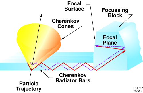
A modified design, as shown in figure 11, employs smaller sized photodetectors as well as focusing optics effectively removing the bar size uncertainty in the focusing plane. These two enhancements can be balanced so that the size of the standoff region can be reduced while keeping a similar or improved geometrical resolution.
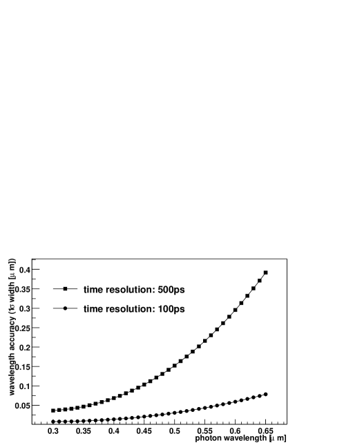
In addition, smaller photodetectors with a better transit time spread will improve the timing resolution of the detector. This can be used to further reduce the background by using tighter time cuts and to reduce the chromatic uncertainty. The travel time of a photon is the difference between the time the particle hits the bar and the arrival time of the photon. It depends on the path length and the group velocity in the transit medium. The group velocity itself depends on the refractive index. Thus, the travel time and path length yield a measure of the wavelength of the photon. Figure 12 shows a calculation demonstrating that a timing resolution in the order of is needed for a significant improvement in the chromatic uncertainty.
Reducing the range of wavelength accepted in the detection system will reduce the range of Cherenkov cone opening angles contributing and, thus, reduce the chromatic uncertainty. The drawback of this solution is the loss in the number of photons detected per track causing a reduced suppression of the single photon resolution term. These two effects can be balanced in order to reach the optimal total resolution.
With a timing resolution in the order of the ratio of the track to detector distance over the path length will provide an additional measure of the photon angle. In some regions of phase space, especially at small dip angles, its resolution will be competitive to the angle resolution from the position of the PMT hit.
A more detailed discussion can be found in [15].
One of the photon detector candidates is the flat panel PMT H-8500 by Hamamatsu[16]. It has square pads on a size of This leads to a high area efficiency and packaging density. The timing resolution is expected to be in the range of to The disadvantage of the currently available model is its low gain in the order of
Studies of the timing resolution on an early pre-production version were encouraging. The time was measured at two thresholds for each signal in order to perform a time walk correction. The corrected time distribution[17] is shown in figure 13. A fit to a double Gaussian plus a second order polynomial describes the data well. The narrow Gaussian has a width of This value is not yet corrected for the light pulse width and instrumentational effects. In addition, the double threshold method limits the data to PMT signals with a pulse height above the higher threshold. This removes some fraction of low signal events.

Currently, studies of the efficiency uniformity of the PMT area are in process and results will be available in near future.
5 Improvements for Future Dirc Detectors
The design described in the previous section will be sufficient to provide the required resolution of the Dirc for possible upgrade scenarios. However, for the SuperB A B AR environment with a design luminosity of the projected occupancy in the tracking system makes building a completely new detector necessary.
This allows to reconsider the radiator and light guide design. Synthetic fused silica is still the material of choice as it fulfills all requirements in terms of transparency, radiation hardness, achievable uniformity in material and optical finish. In addition, it has a small radiation length which is benifical for a calorimeter outside of the Dirc system.
Increasing the thickness of the radiators will lead to an increased number of photons per track but it will also increase the amount of material in front of the calorimeter, so the thickness of the radiator can not be changed significantly.
Increasing the width of the radiators, such as using one plate instead of several bars, has advantages in the geometrical term of the single photon resolution. In a plate geometry, there are less side bounces and the path length for a photon measured in a given PMT with a known track position changes drastically with each additional side bounce. Therefore, the hit time can be used to determine the number of side bounces and because of this the exit position of the photon at the instrumented bar end can be inferred. This is shown in figure 14, where the full line and the dashed line have significantly different path lengths.

There are a few examples in the following on the expected resolution for the different setups. A detailed discussion of the geometries can be found in [15]. Please note that the resolutions are given in terms of the photon exit angles at the end of the bar or plate. These are different to the Cherenkov angle resolution However, there is a strong correlation between and while the correlation between and is weaker.
Current B A B AR Dirc
The current Dirc setup has round PMTs with diameter and rectangular bars of size The resolution on the photon exit angle at the edge of the bar is
| (3) |
and
| (4) |
The interface fused silica — water magnifies the angles thus improving the resolution by approximately 10% leading to
Focusing optics for B A B AR like Dirc
A focusing optic in with a pixel size of and a corresponding standoff distance of leads to
| (5) |
similar to the current resolution. The resolution in will get worse as focusing in both dimensions would complicate ambiguity resolution. This can be compensated by the reduced chromatic uncertainty.
Focusing optics with plates for SuperB A B AR
In order to improve the resolution, a smaller pad size of in direction and in direction can be used. The resolution can be described by
| (6) |
in direction and in
| (7) |
In the last equation is the length of the region where the photon can expand without side bounces. This length varies depending on the number and positions of the side bounces.
Together with the improved chromatic resolution, this leads to a significant improvement in the single photon resolution compared to the current B A B AR Dirc.
The major uncertainty not directly related to the Dirc design is the correlated uncertainty on the position of the track at the entry into the radiator. In order to improve the particle separation, it is not sufficient to improve the intrinsic Dirc uncertainty only. A possible solution is to add a tracking device outside the Dirc volume. This would also allow for finding particle conversions and decays inside the radiator material.
A further improvement is to enlarge the angular coverage of the particle identification system by using an end-cap device. The Dirc covers the barrel region only. Additional challenges for an end-cap device are the limited amount of space in the end-cap, the higher radiation levels close to the beam-pipe, and that the readout has to be done inside the magnetic field which makes standard PMTs unusable. Interesting alternative photodetectors have been suggested but they still need to be studied in detail before an evaluation on the feasibility of an end-cap Dirc can be performed.
6 Conclusions
The Dirc is a novel particle identification system used for the first time in the B A B AR environment. It is performing close to the design and has a significant influence on most physics analysis.
Increasing the luminosity beyond the B A B AR design values will result in challenges for the Dirc system mainly due to increased background levels of low energy photons from Pep-II. Improvements in shielding and in the maximal data taking rate will allow for running the current detector up to the anticipated Pep-II limits. Beyond that, reducing the size of the standoff box will be necessary. In order to keep the Cherenkov angle resolution on the design level, the standoff box needs to be replaced by focusing optics with smaller sized photodetectors. Timing resolution in the order of is vital to reduce the chromatic uncertainty and can effectively separate signal from background photons. Research on candidate devices has started and first tests have shown promising results.
At luminosities in the order of as envisioned for SuperB A B AR, a completely new Dirc can be built. Fused silica plates instead of bars and even smaller PMT pad sizes along with an improved tracking will allow for significant improvements in the Cherenkov angle resolution.
Enlarging the angular coverage of a Dirc particle identification system will require an end-cap device. The challenges for this device include photodetection inside of the magnetic field and the limited amount of space prohibiting large expansion volumes.
References
-
[1]
The B A B AR-Dirc Collaboration:
R. Aleksan,2
D. Aston,1
D. Bernard,5
G. Bonneaud,5
P. Bourgeois,2
F. Brochard,5
D.N. Brown,6
J. Chauveau,3
J. Cohen-Tanugi,5
M. Convery,1
S. Emery,2
S. Ferrag,5
A. Gaidot,2
T. Hadig,1
G. Hamel de Monchenault,2
C. Hast,4
A. Hoecker,4
R.W. Kadel,6
J. Kadyk,6
M. Krishnamurthy,8
H. Lacker,4
G.W. London,2
A. Lu,7
A.-M. Lutz,4
G. Mancinelli,9
N. Mayer,2
B.T. Meadows,9
Ll.M. Mir,6
D. Muller,1
J. Ocariz,3
T. Petersen,4
M. Pivk,4
S. Plaszczynski,4
M. Pripstein,6
B.N. Ratcliff,1
L. Roos,3
M.-H. Schune,4
J. Schwiening,1
V. Shelkov,6
M.D. Sokoloff,9
S. Spanier,1
J. Stark,3
A.V. Telnov,6
Ch. Thiebaux,5
G. Vasileiadis,5
G. Vasseur,2
J. Va’vra,1
M. Verderi,5
W.A. Wenzel,6
R.J. Wilson,8
G. Wormser,4
A. Yarritu,1
Ch. Yéche,2
S. Yellin,7
M. Zito.2
1Stanford Linear Accelerator Center, Stanford, CA 94309, USA.
2CEA, DAPNIA, CE-Saclay, F-91191, Gif-sur-Yvette Cedex, France.
3LPNHE des Universités Paris 6 et Paris 7, Tour 33, Bc 200, 4 Place Jussieu, F-75252, Paris, Cedex 05, France.
4LAL Orsay, Universite Paris Sud, Batiment 200, F-91405 Orsay Cedex, France.
5LPNHE de l’Ecole Polytechnique, Route de Saclay, F-91128 Palaiseau Cedex, France.
6Lawrence Berkeley National Laboratory, One Cyclotron Road, Berkeley, CA 94720, USA.
7Dept. of Physics, University of California, Santa Barbara, CA 93106, USA.
8Dept. of Physics, Colorado State University, Fort Collins, CO 80523, USA.
9Dept. of Physics, University of Cincinnati, Cincinnati, OH 45221, USA.
Work supported by Department of Energy contract DE–AC03–76SF00515 (SLAC), DE-AC03-76SF00098 (LBNL), DE-AM03-76SF0010 (UCSB), and DE-FG03-93ER40788 (CSU); the National Science Foundation grant PHY-95-11999 (Cincinnati). - [2] P. F. Harrison and H. R. Quinn [B A B AR Collaboration], “The B A B AR physics book: Physics at an asymmetric B factory,” SLAC-R-0504 Papers from Workshop on Physics at an Asymmetric B Factory (B A B AR Collaboration Meeting), Rome, Italy, 11-14 Nov 1996, Princeton, NJ, 17-20 Mar 1997, Orsay, France, 16-19 Jun 1997 and Pasadena, CA, 22-24 Sep 1997.
- [3] B. Aubert et al. [B A B AR Collaboration], “The B A B AR detector,” Nucl. Instrum. Meth. A 479, 1 (2002) [arXiv:hep-ex/0105044].
-
[4]
B. Ratcliff,
“The B factory detector for PEP-II: A Status report,”
SLAC-PUB-5946
Presented at 26th International Conference on High Energy Physics
(ICHEP 92), Dallas, TX, 6-12 Aug 1992;
B. Ratcliff, “The Dirc counter: A new type of particle identification device for B factories,” SLAC-PUB-6047 Presented at International Workshop on B Factories: Accelerators and Experiments, Tsukuba, Japan, 17-20 Nov 1992;
P. Coyle et al., “The Dirc counter: A new type of particle identification device for B factories,” Nucl. Instrum. Meth. A 343, 292 (1994). - [5] Spectrosil is a trademark of TSL Group PCL, Wallsend, Tyne on Wear, NE28 6DG, England; Sold in the USA by Quartz Products Co., Louisville, KY, USA.
-
[6]
I. Adam et al. [B A B AR-Dirc Collaboration],
“Dirc, the internally reflecting ring imaging Cherenkov detector for B A B AR,”
IEEE Trans. Nucl. Sci. 45, 657 (1998)
[arXiv:hep-ex/9712001];
I. Adam et al. [B A B AR-Dirc Collaboration], “An internally reflecting Cherenkov detector (Dirc): Properties of the fused silica radiators,” ibid, pp 450;
J. Cohen-Tanugi, M. Convery, B. Ratcliff, X. Sarazin, J. Schwiening and J. Vavra, “Optical properties of the Dirc fused silica Cerenkov radiator,” ICFA Instrum. Bull. 21, 20 (2001). - [7] Electron Tubes Limited (formerly: Thorn EMI Electron Tubes), Ruislip, Middlesex, England.
- [8] P. Bourgeois, M. Karolak and G. Vasseur, “Performance of the photomultiplier tubes used in the Dirc of B A B AR: Effect of a magnetic field and of helium,” Nucl. Instrum. Meth. A 442, 105 (2000).
- [9] M. Benkebil, R. Cizeron, S. Plaszczynski, M. H. Schune and G. Wormser, “Water Resistant Rhodium Plated Reflectors For Use In The Dirc B A B AR Cherenkov Detector,” Nucl. Instrum. Meth. A 442, 364 (2000).
- [10] Boeing Optical Fabrication, Albuquerque, NM, USA.
- [11] E. Antokhin et al., “Simulation and measurement of the fringe field of the 1.5-Tesla B A B AR solenoid,” Nucl. Instrum. Meth. A 432, 24 (1999).
- [12] P. Bailly, J. Chauveau, J. F. Genat, J. F. Huppert, H. Lebbolo, L. Roos and B. Zhang, “A 16-Channel Digital TDC Chip,” Nucl. Instrum. Meth. A 433, 432 (1999).
- [13] A. Yarritu, S. Spanier and J. Va’vra, “Photon background in Dirc fused silica bars,” SLAC-PUB-9073, to be published in IEEE Trans. Nucl. Sci. Presented at 2001 IEEE Nuclear Science Symposium (NSS) and Medical Imaging Conference (MIC), San Diego, California, 4-10 Nov 2001.
- [14] I. Adam et al., “Operational experience with the Dirc detector,” SLAC-PUB-9088 Invited talk at 2001 IEEE Nuclear Science Symposium (NSS) and Medical Imaging Conference (MIC), San Diego, California, 4-10 Nov 2001.
-
[15]
B. N. Ratcliff,
“Dirc dreams redux: Research directions for the next generation of
internally reflected imaging counters,”
ICFA Instrum. Bull. 22, 03 (2001);
B. N. Ratcliff, “Imaging Rings in Ring Imaging Cherenkov Counters,” Invited talk at RICH2002, Pylos, Greece, June 2002, SLAC-PUB-9508, to be published in Nucl. Instrum. Meth. A. - [16] Hamamatsu Photonics K.K., http://www.hamamatsu.com/
- [17] Jerry Va’vra, “Novel Photon Detectors for RICH Applications,” Invited talk at RICH2002, Pylos, Greece, June 2002.