An MT-Style Optical Package for Optical Data Transmission
Abstract
An optical package for mounting VCSEL and PIN diodes for transmitting and receiving optical signals has been developed. The diodes couple to the fibers in a commercial MT connector. The package is quite compact with its physical size significantly smaller than that of the MT connector. This design simplifies the testing and assembly of the optical components because the MT connector with the long fibers attached can be remounted with ease while preserving good light coupling efficiency.
keywords:
optical package , MT connectorPACS:
29.40-n1 Introduction
Optical fibers are now replacing traditional copper wires for signal transmission in the detectors for high energy and nuclear physics research. Optical fibers are more compact than copper wires, freeing up valuable detector space, and allow signal transmission over long distances with small attenuation. More importantly, the fibers eliminate electromagnetic interference and ground loops.
Commercially available VCSEL (Vertical Cavity Surface Emitting Laser) or PIN packages for transmitting and receiving optical signals are quite bulky. Detectors for high energy and nuclear physics research using optical packages usually need to custom design their packages due to space constraints. The problem is especially severe for the vertex detector located within the vicinity of the beam colliding region. In this paper, we present a compact MT-style optical package for housing VCSEL and PIN diodes. The diodes couple to the fibers in a commercial MT connector. This design simplifies the testing and assembly of the optical components because the MT connector with the long fibers attached can be remounted with ease while preserving good light coupling efficiency. In the next section, we present the design of the package. This is followed by a section on the prototype results and then a summary.
2 Optical Package Design
The optical package is a two-piece design as shown in Fig. 1. The U-shaped receptor contains two holes for the guide pins. Each hole has a diameter of m and the distance between the two holes is m. The tolerances for the two dimensions are from the MT connector specification [1], hence the same tolerances should be used in the optical package fabrication. The receptor can be made of plastic with mold injection.
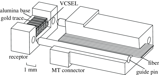
The base inside the receptor is fabricated using alumina. The two pieces are glued together with epoxy. On the side of the base facing the fibers, there are two gold traces for each VCSEL or PIN diode. One of the traces is for the cathode and the other for the anode. A diode is attached to one of the traces with conducting epoxy and a wire bond connects the other trace to the pad on the top of the diode. The two traces go over the corner to the other side of the base and connect via wire bonds to the optical transmitter or receiver chip placed in close proximity. The top traces are 1.5 mm in length, hence the chip is connected to the diode with small stray capacitance and inductance, minimizing degradation of the electrical signal. This is one of the advantages of this optical package design. The base should be placed at a location such that the distance between the diode and the fiber is m for good light coupling efficiency.
To fabricate the bases, alumina sheet is ground to the proper thickness of the bases and then cut into strips for deposition of three-dimensional traces [2]. The trace width is 150 m and the gap between traces is 75 m. Most of the deposited traces ( 94%) have good connectivity across the corner of the strips. Strips with a large number of traces of good connectivity are then diced into individual bases.
The main technical challenge in the fabrication of the package is the stringent alignment tolerance of the VCSEL with respect to the fiber location. Since the light from the VCSEL is highly collimated, the VCSEL must be placed radially within m of the center of the fiber for good light coupling efficiency. The distance between the VCSEL and the end of the fiber is much less critical and we choose 200 m for the design shown in Fig. 1.
The alignment tolerance for the PIN diode is not stringent because the light sensitive area of the PIN is large compared with the silica core of the fiber. Consequently, we have demonstrated the principle of the design by prototyping the VCSEL optical package only.
For the placement of the VCSEL and PIN diodes, a small drop of conducting epoxy is deposited on a trace at the location of interest. A diode is then placed on top of the epoxy and aligned. Since the location of the fibers in an MT connector are defined precisely with respect to the two guide pins, one can align the diode with respect to the center of the two holes in the receptor under an optical comparator. Alternatively, one can mount an MT connector with fibers attached on the optical package and shine light into the other end of the fibers. With the MT connector pulled back slightly from the optical package, one can see a bright spot on the face of the diode. The diode should then be moved so that the most sensitive area is in the center of the beam spot.
There are many design variations depending on the requirements of an experiment. If only one or two channels are needed in an optical package, one can use the much smaller mini-MT connector. A typical MT connector has either 8 or 12 fibers in a row with 250 m between the centers of adjacent fibers. The number of VCSEL/PIN diodes that can be placed on a base depends on the physical dimension of the diodes. In the example shown in Fig. 1, one can place six diodes, thus only half of the fibers are used. Alternatively, one can fabricate MT connectors with wider fiber spacing to accommodate the physical size of the diodes. There are MT connectors that can connect up to 72 fibers in a 6 12 matrix [1]. By staggering the diodes instead of arranging them in a row to circumvent the diode physical size limitation, one can place more diodes in a package. If only a small number of diodes is used in a package, one can add a wide ground trace between two signal traces to act as a ground plane for shielding to reduce potential crosstalk. One can of course use a mixture of VCSEL and PIN diodes in the same package so that the package provides two-way communication. One can also use a common cathode VCSEL or PIN array in the package instead of individual diodes. In this case, the number of traces is reduced by half and a trace is added for the common cathode connection.
3 Prototype Results
We fabricated several prototype VCSEL optical packages in order to test the principle of the design. As stated in the previous section, we only demonstrated the principle on the VCSEL optical package and not on the PIN package, due to the more stringent VCSEL alignment tolerances. We used VCSELs manufactured by Truelight [3]. The physical dimension of the VCSEL was , hence we could only place six VCSELs on a base for use with a 12-fiber MT connector as shown in Fig. 1. In principle, we could fabricate the U-shaped receptor using mold injection. However, this would be somewhat time consuming and not cost effective for a prototype test. We therefore cut an MT connector into three pieces and machined out a pocket for the base in each piece. This automatically guaranteed that the guide pin hole diameter and separation were within the mechanical specification. In fact, this is a viable alternative to mold injection for any project requiring only a few hundred packages. Care must be exercised in the machining or else the plastic receptor could crack.
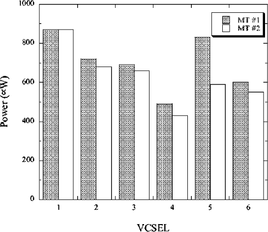
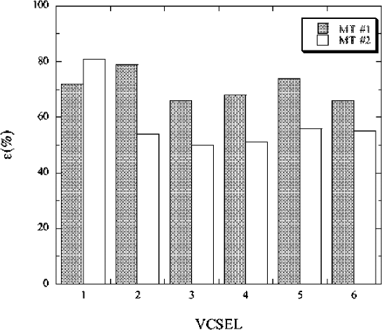
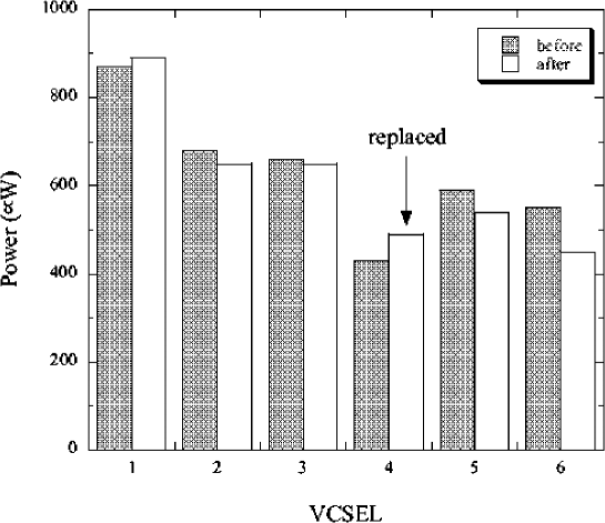
Figure 2 shows the coupled VCSEL power for a 10 mA current through the VCSEL for two prototype packages. All channels have good coupled power, 400 W or above. The power coupling efficiency is shown in Fig. 3. All channels have good efficiency, 50% or higher. We have also tested the feasibility of replacing one of the VCSELs as may be needed in a production when a VCSEL is damaged or misaligned. Figure 4 shows the coupled optical power of all VCSELs before and after the repair. It is evident that the coupled power of the VCSELs after the repair are consistent with those before the operation. This demonstrates that a VCSEL can be replaced without damaging other channels.
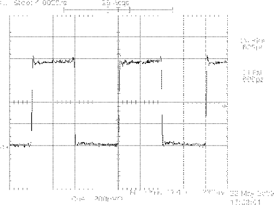
The optical signal from the VCSEL is of high quality as shown in Fig. 5. Both the rise and fall times of the signal are fast, ps.
4 Summary
In summary, we have demonstrated the principle of an MT-style optical package. The VCSELs in the optical package have good coupled power (efficiency). The package is quite compact and individual VCSEL or PIN diodes in the package can be replaced if necessary. This package design simplifies the testing and assembly of the optical components because the MT connector with the long fibers attached can be remounted with ease while preserving good light coupling efficiency.
5 Acknowledgement
The author wishes to thank K. Arms, J. Burns, R.D. Kass, S. Smith, and R. Wells for their contributions.
References
- [1] See for example, http://www.xanoptix.org/connectorsspecs.htm.
- [2] Hybrid-Tek Inc., 1 Hytek Corporate Ctr, Rte. 526, Clarksburg, NJ 08510, USA.
- [3] Truelight Corporation, Hsinchu, Taiwan.