Ultra High Precision with a Muon Storage Ring†
Abstract
The Muon experiment, E821, at the Brookhaven AGS has the goal to measure the muon anomalous magnetic moment to a relative accuracy of . A superferric 14 m diameter storage ring has been constructed and an averaged magnetic field uniformity over the 90 mm diameter muon storage region of 1 part per million (ppm) has been achieved. A truncated double-cosine superconducting septum magnet (the inflector) was constructed along with a fast non-ferric kicker. The performance of the storage ring, along with the physics results are reviewed.
1 Introduction
The measurement of magnetic moments has been important in advancing our knowledge of sub-atomic physics since the famous 1921 paper of Stern,[2] which laid out the principles of what we now call the “Stern-Gerlach experiment”. The experimental and theoretical developments in the study of the electron’s magnetic moment represent one of the great success stories of modern physics, with the experiment reaching a relative accuracy of parts in (parts per billion)[3] and the theory being constrained by our knowledge of the fine-structure constant , rather than by the eight-order and tenth-order QED calculations.[4]
The gyromagnetic ratio is defined by , where is the spin angular momentum, and is the magnetic moment resulting from this angular momentum. The Dirac equation predicts that , but radiative corrections increase the value at the part per mil level. The Particle Data Tables define the magnetic moment as where is the anomalous magnetic moment (or simply the anomaly).
When E821 began in the early 1980s, was known to 7.3 parts per million (ppm).[5] The E821 Collaboration has reported three new measurements with relative accuracies of 13, 5 and 1.3 ppm respectively.[6, 7, 8]
To the level of the experimental accuracy, the electron anomaly can be described by the QED of and photons, with the contribution of heavier virtual particles entering at a level below 4 ppb. The larger mass of the muon permits heavier virtual particles to contribute, and the enhancement factor is . The CERN measurement observed the effect on of virtual hadrons at the 10 standard deviation level.[5] The standard model value of consists of QED, strong interaction and weak radiative corrections, and a significant deviation from the calculated standard model value would represent a signal for non-standard model physics.
2 The Experimental Technique
The method used in the third CERN experiment and the BNL experiment are very similar, save the use of direct muon injection into the storage ring which was developed by the E821 collaboration. They are based on the fact that for (or more precisely ) the spin gets ahead of the momentum vector when a muon travels transversely to a magnetic field. The Larmor and Thomas spin-precession and the momentum precession frequencies are
| (1) |
and the difference frequency gives the frequency with which the spin precesses relative to the momentum,
| (2) |
which is proportional to the anomaly, rather than to the full magnetic moment. A precision measurement of requires precision measurements of the precession frequency and the magnetic field. The muon frequency can be measured as accurately as the counting statistics and detector apparatus permit. The design goal for the NMR magnetometer and calibration system was a field accuracy of about 0.1 ppm. The which enters in Eq. 2 is the average field seen by the ensemble of muons in the storage ring, where is the azimuthal angle around the ring, are the coordinates at a single slice of azimuth centered at the middle of the 90 mm diameter muon storage region. is the moment (multipole) distribution of the muon distribution, and couples multipole by multipole with the magnetic field. It is very difficult to obtain adequate information on the higher moments of the muon distribution in the storage ring, so the presence of higher multipoles in the magnetic field is undesirable.
The need for vertical focusing implies that a gradient field is needed, but the usual magnetic gradient used in storage rings is ruled out in our case. A sufficient magnetic gradient for vertical focusing would spoil the ability to use NMR to measure the magnetic field to the necessary accuracy, and would also require detailed knowledge of the muon distribution.
An electric quadrupole is used instead, taking advantage of the “magic” at which an electric field does not contribute to the spin motion relative to the momentum. This can be understood from the famous Thomas-BMT equation
| (3) |
which reduces to Eq. 2 in the absence of an electric field. Note that for muons with in an electric field alone, the spin would follow the momentum vector.
The arrangement of a magnetic dipole field combined with an electric quadrupole field is called a Penning trap in atomic physics. However with a 14 m diameter and T weight, the scale of our trap is quite different from the usual one.[3]
In order to meet the conditions discussed above, a goal of ppm uniformity of the -field over the storage region was set and met. A round beam profile was chosen, since sharp corners would imply large higher moments for . Given the projected knowledge of the muon distribution, the allowable strength of the quadrupole and higher magnetic multipoles was also determined. The quadrupoles are arranged in a four-fold symmetry covering 43% of the ring. This geometry has the advantage that to about 5% so the beam does not breathe very much, making the average field calculation easier.
In our optimal running conditions, the 24 GeV/c proton beam in the AGS is accelerated in 12 proton bunches, each with an intensity of about protons. The bunches are extracted one at a time at 33 ms intervals, and brought down a transport line to a Ni production target. The time distribution of the proton beam has ns. The AGS cycle time is about 2.8 s.
Pions at are momentum analyzed and then brought into a 72 m straight FODO decay channel where muons are born. A second momentum slit permits one to choose forward muons about 1.6% below the pion momentum. These forward muons have % longitudinal polarization, and are injected into the ring where their spin precesses. We store on the order of muons per fill of the ring.
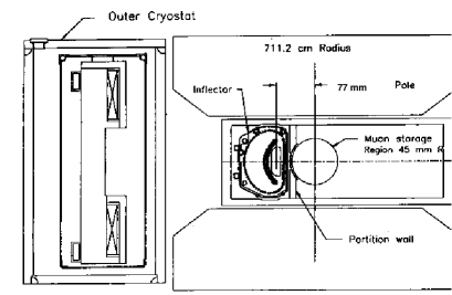
Unlike the conventional storage ring made of lumped elements, the requirement of a field uniform at the ppm level precluded breaks in the storage ring magnet. Thus the beam must be brought in through the fringe field of the storage ring to a point close the the central orbit. This is achieved by the use of a 1.7 m superconducting inflector magnet[9] which nulls the field where the beam enters, but does not leak flux into the storage region, spoiling the precision field. An elevation view of the inflector exit, and the magnet is shown in Fig. 1. This unconventional set of conditions means that there is no phase-space matching between the incoming beam and the storage ring. This mismatch reduces the calculated injection efficiency to %.
A kick of about 0.1 Tm is needed to bring the beam onto a stable orbit. This is achieved with three 1.7 m long ferrite-free kickers,[10] which can be thought of as single-loop pulsed magnets carrying a current of 4,200 A. The minimum inductance achievable of 1.6 H limited the peak current to 4200A, and resulted in a current-pulse width times greater than the cyclotron period. This less than optimal kicker pulse reduces the injection efficiency to about 7.3%. Nevertheless the number of stored muons per fill is almost a factor of 100 over that available in the final CERN experiment,[5] and the injection-related background seen by the detectors is down by a factor of 50.[6, 7]
The precision magnetic field is at the heart of the experiment.[11] A profile of the storage ring magnet is given in Fig. 2.
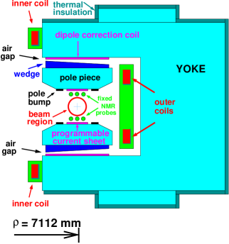
The air-gap dominates the reluctance of the magnetic circuit, and the pole-pieces are made of very low carbon, high quality magnet steel. The angle of the iron wedge in the air gap is used to eliminate the quadrupole inherent in a “C” magnet, and the wedge can be moved radially to adjust the dipole locally. The pole bumps were ground individually to minimize the sextupole component, and the pole face windings (programmable current sheet) permit one to minimize the higher multipoles (on average), which do not vary much around the ring.
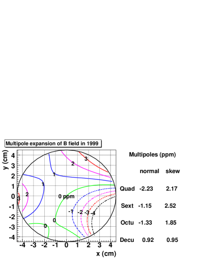
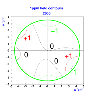
The success in shimming the magnet can be seen in Figs. 3 and 4, which show the average field from 1999 and 2000. The poorer field quality in ’99 came from a damaged passive superconducting shield around the inflector, which permitted flux leakage into the storage ring. In 2000 the damaged inflector was replaced, and we met the goal of ppm uniformity. Several important parameters of the storage ring are given in Table 1.
The experimental signal is the from decay. Muon decay is a three-body decay, so the 3.1 GeV muons produce a continuum of positrons (electrons) from the endpoint energy down. Since the highest energy are correlated with the muon spin, if one counts high energy as a function of time, one gets an exponential from muon decay modulated by the precession. The expected form for the positron time spectrum is
| (4) |
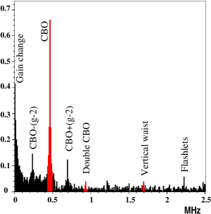
However, a Fourier analysis of the residuals from this five parameter fit shows a number of frequency components which can only be understood after a discussion of the beam dynamics in the ring (see Fig. 5).
| Parameter | Value |
|---|---|
| Frequency | Hz |
| Period | s |
| Muon Kinematics | GeV/c |
| s | |
| Cyclotron Period | ns |
| Central Radius | mm |
| Magnetic Field | T |
| Storage Aperture | cm circle |
| In one lifetime: | 432 revolutions |
| 14.7 (g-2) periods |
3 Beam Dynamics
The ring is a weak focusing ring with
| (5) |
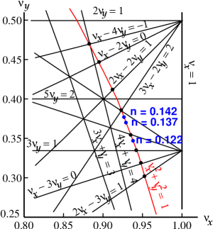
where is the electric quadrupole gradient. Several - values were used for data acquisition: and 0.122. The horizontal and vertical betatron frequencies are approximately given by
| (6) |
where is the cyclotron frequency and the numerical values assume .
The detector acceptance depends on the radial position of the muon when it decays, so any coherent radial beam motion will amplitude modulate the decay distribution. The principal frequency will be the “Coherent Betatron Frequency”
| (7) |
which is the frequency a single fixed detector sees the beam moving coherently back and forth. An alternate way of thinking about this frequency is to view the ring as a spectrometer where the inflector exit is imaged at each successive betatron wavelength. In principle an inverted image appears at half a betatron wavelength, but the radial image is spoiled by the % momentum dispersion of the ring. A given detector will see the beam move radially with the CBO frequency, which is also the frequency that the horizontal waist precesses around the ring. However, since there is no dispersion in the vertical dimension, the vertical waist is reformed every half a wavelength. The CBO frequency and its sidebands are clearly visible in the Fourier spectrum, and the vertical waist is just seen. A number of frequencies in the ring are tabulated in Table 2
| Quantity | Expression | Frequency | Period |
|---|---|---|---|
| 0.23 MHz | 4.37 s | ||
| 6.7 MHz | 149 ns | ||
| 6.23 MHz | 160 ns | ||
| 2.48 MHz | 402 ns | ||
| 0.477 MHz | 2.10 s | ||
| 1.74 MHz | 0.574 s |
The tune plane is shown in Fig.6 which shows resonance lines up to fifth order. Of the three -values used for data collection, the tune had a CBO frequency uncomfortably close to the second harmonic of (see Table 2 putting an AM sideband just by the frequency. This nearby sideband and has forced us to to work very hard to understand the CBO and how its related phenomena affect the value of from the fits to the data. The 2001 data set was taken with the other two tunes, which substantially reduced our sensitivity to the CBO.
4 Monitoring the Beam Profile
Three tools were available to us to monitor the muon distribution. By studying the beam debunching after injection, one can gain information on the distribution of equilibrium radii in the storage ring. A wire chamber system located at one position around the ring permitted us to measure the trajectories of the and by tracing the trajectory back to the point where it is tangent to the ring, reproduces the decay position to within a few mm. The ring was equipped with two sets of scintillating fiber beam monitors which could be plunged into the storage region. Each set consisted of an and plane of seven 0.5 mm diameter scintillating fibers which covered the beam region.
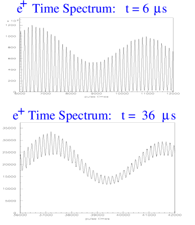
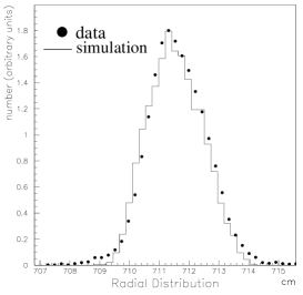
In Fig. 7 the signal from a single detector is shown at two different times following injection. The bunched beam is seen very clearly in the top figure, with the 149 ns cyclotron period being obvious. The slow amplitude modulation comes from the precession. By 36 s the beam has largely de-bunched. In Fig. 8 the inferred distribution of equilibrium radii is shown along with that obtained from a monte carlo tracking code. The agreement is seen to be good, and the measured distribution was used in determining the average magnetic field and the radial electric field correction.
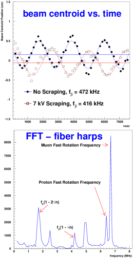
The scintillating fiber monitors showed clearly the vertical and horizontal tunes as expected. Fig. 9 the beam centroid motion is shown, both with the quadrupoles powered asymmetrically during scraping, and symmetrically after scraping. A Fourier transform of the latter signal shows clearly the expected frequencies. The traceback system also clearly sees the CBO motion. Additional details on beam dynamics will be available in Ref. [12]
A physics result with a total error of 1.3 ppm was obtained from our 1999 data set.[8] The result was originally 2.6 standard deviations above the predicted standard model value, creating an outpouring of interest, and much speculation that the first evidence for supersymmetry had been obtained. However, a sign mistake in a small piece of the theoretical hadronic contribution improved the agreement to 1.6 . We have an additional data set with which will have a total error of around 0.8 ppm, and also a data set which should also have a similar error, although the distribution between statistical and systematic errors is different for the two data sets.
The theory value is also being refined further, and we hope that both theory and experiment will have presented new values by September 2002.
5 Conclusions
The muon collaboration has successfully built and operated a superferric storage ring with unprecedented field uniformity over such a large volume. All aspects of the apparatus, inflector, main magnet, kicker, electrostatic quadrupoles, detector system and electronics have achieved the design specifications. Interest in our new results remains high, and we look forward to improvements from our theoretical colleagues, which will improve the sensitivity of the comparison to the standard model.
Acknowledgements I wish to thank my colleagues, K. Jungmann, J. Paley, E. Sichtermann, and Y.K. Semertzidis for their critical readings of, and suggested improvements for this manuscript.
References
- [1] The present Collaboration: R.M. Carey, X. Huang, A. Lam-Ng, I. Logashenko, J.P. Miller, J. Paley, B.L. Roberts - Boston University; G. Bennett, H.N. Brown, G. Bunce, G.T. Danby, Y.Y. Lee, W. Meng, W.M. Morse, D. Nikas, C. Özben, R. Prigl, Y.K. Semertzidis - Brookhaven National Laboratory; Y. Orlov - Cornell University; D. Winn - Fairfield University; K. Jungmann -KVI Groningen; G. zu Putlitz - University Heidelberg; P.T. Debevec, F. Gray D.W. Hertzog, C. Onderwater, C. Polly, M. Sossong - University of Illinois, Urbana Champaign; A. Yamamoto - KEK B. Bousquet, P. Cushman, R. McNabb, T. Qian, P. Shagin - University of Minnesota; V.P. Druzhinin, G.V. Fedotovich, B.I. Khazin, N.M. Ryskulov, Yu.M. Shatunov, E. Solodov - Budker Institute; M. Iwasaki - Tokyo Institute of Technology; H. Deng, M. Deile, S.K. Dhawan, F.J.M. Farley, V.W. Hughes, S.I. Redin, E. Sichtermann - Yale University
- [2] Otto Stern, Z. Phys. 7, 249 (1921).
- [3] R.S. Van Dyck et al., Phys. Rev. Lett., 59, 26(1987) and in Quantum Electrodynamics, (Directions in High Energy Physics Vol. 7) T. Kinoshita ed., World Scientific, 1990, p.322.
- [4] T. Kinoshita, Rept. Prog. Phys., 59, 1459(1996).
- [5] J. Bailey, et. al, Nucl. Phys. B150,1(1979).
- [6] R.M. Carey et al., Phys. Rev. Lett82,1632(1999).
- [7] H.N. Brown et al., (Muon Collaboration), Phys. Rev. D62, 091101 (2000).
- [8] H.N. Brown, et al., (Muon Collaboration), Phys. Rev. Lett. 86 2227 (2001).
- [9] F. Krienen, D. Loomba and W. Meng, Nucl. Inst. and Meth. A283, 5 (1989), and W. Meng et al., in press.
- [10] E. Efstathiadis, et al., Nucl. Inst. and Meth. in press.
- [11] G.T. Danby, et al., Nucl. Instr. and Meth., A 457, 151-174 (2001).
- [12] E. Bennedict, et al., Beam Dynamics in the Muon Storage Ring, in preparation for Nucl. Inst. and Meth.