Budker INP 2002-47
Interaction region for collisions
at linear colliders
Abstract
Photon colliders (, e) are based on backward Compton scattering of laser light off the high energy electrons in linear colliders. All projects of linear colliders include this option. In this paper physics motivation, possible parameters and some interaction region aspects of photon colliders are discussed.
PACS: 29.17.+w, 41.75.Ht, 41.75.Lx, 13.60.Fz
keywords:
photon collider; linear collider; photon photon; gamma gamma; electron photon; photon electron; Compton scattering; backscattering;1 Introduction
Linear colliders, LC, at the center of mass energy from 100 GeV up to several TeV will be one of the central instruments in experimental high energy physics in the next 2 to 3 decades. Four projects are being developed: NLC [1], TESLA [2], JLC [3], and CLIC [4]. TESLA team has published in March 2001 the Technical Design of the superconductiing linear collider on the energy 90–800 GeV [2].
The unique feature of the Linear Colliders is the possibility to construct on its basis a Photon Collider using the process of the Compton backscattering of laser light off the high energy electrons [5, 6, 7, 8]. This option is considered now for all linear colliders projects: NLC [1]; TESLA [9, 10, 11]; JLC [12, 13, 3]; CLIC [14].
In the following we discuss the physics programme, possible laser and optical schemes, the expected and e luminosities and some other interaction region aspects. Examples are given mostly for the photon collider at TESLA, other projects are also discussed where they have principle differences.
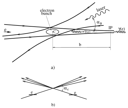
The basic scheme of the Photon Collider is shown in Fig. 1. Discussion of the photon collider scheme and basic principles can be found elsewhere [5, 6, 7, 8, 9, 10, 11].
Let us remind main features of photon colliders. The maximum energy of the scattered photons is [5]
| (1) |
where is the electron beam energy and the energy of the laser photon. For example, for , () (powerful solid state lasers) we obtain and (it will be somewhat lower due to nonlinear effects in Compton scattering.
The value is a good choice for photon colliders, because for the produced high energy photons create QED e+e- pairs in collision with the laser photons, and as result the luminosity is reduced [5, 7, 8]. Hence, the maximum center of mass system energy in collisions is about 80%, and in e collisions 90% of that in e+e- collisions. If for some study lower photon energies are needed, one can use the same laser and decrease the electron beam energy. The same laser with can be used for all TESLA energies. At the parameter , which is larger than 4.8. But nonlinear effects at the conversion region effectively increase the threshold for e+e- production, so that e+e- production is significantly reduced [11].
The luminosity distribution in collisions has a high energy peak and a low energy part. The peak has a width at half maximum of about 15%. The photons in the peak can have a high degree of circular polarization. This peak region is the most useful for experimentation. When comparing event rates in and e+e- collisions usually we use the value of the luminosity in this peak region where .
The energy spectrum of high energy photons becomes most peaked if the initial electrons are longitudinally polarized and the laser photons are circularly polarized. This gives almost a factor of 3–4 increase of the luminosity in the high energy peak. The average degree of the circular polarization of the photons within the high-energy peak amounts to 90–95%. The sign of the polarization can easily be changed by changing the signs of electron and laser polarizations.
The luminosity in the high energy luminosity peak for TESLA is just proportional to the geometric luminosity of the electron beams: . The latter can be made larger for collisions than the e+e- luminosity because beamstrahlung and beam repulsion are absent for photon beams. It is achieved using beams with smallest possible emittances and stronger beam focusing in the horizontal plane (in e+e- collisions beams should be flat due to beamstrahlung). For current TESLA parameters [10, 11] (see details in Section 3)
| (2) |
Approximately similar luminosities are expected in e collisions. Typical cross sections in collisions are about one order of magnitude higher than those in e+e- collisions therefore the number of interesting events at photon colliders will be similar of even higher than in e+e- collisions.
2 Physics motivation
The physics potential of the Photon Collider is very rich and complements in an essential way the physics program of the e+e- mode. A few examples:
-
•
In collisions, resonances with are produced as single resonances. The effective cross section of the production at photon colliders is even higher that in e+e- collisions [16]. One of the most important examples is the Higgs boson. The precise knowledge of its two–photon width is of particular importance. It is sensitive to heavy virtual charged particles. Supersymmetry predicts three neutral Higgs bosons. Photon colliders can produce the heavy neutral Higgs bosons with masses about 1.5 times higher than in e+e- collisions at the same collider (because heavy Higgs bosons and have almost equal masses and in e+e- collisions are produced in pairs).
-
•
A collider can produce pairs of any charged particles (charged Higgs, supersymmetric particles etc.) with a cross section about one order of magnitude higher than those in e+e- collisions (see graphs elsewhere [8, 9, 11]. Moreover, the cross sections depend in a different form on various physical parameters. The polarization of the photon beams and the large cross sections allow to obtain valuable information on these particles and their interactions.
-
•
At a e collider charged particles can be produced with masses higher than in pair production of e+e- collisions (like a new boson and a neutrino or a supersymmetric scalar electron plus a neutralino).
-
•
Photon colliders offer unique possibilities for measuring the fusion of hadrons for probing the hadronic structure of the photon.
A short list of physics processes for the photon collider is presented in Table 1 [17]. More detail consideration of the physics program at photon colliders can be found elsewhere [18, 16, 19, 17, 11, 3].
| Reaction | Remarks |
|---|---|
| GeV | |
| MSSM heavy Higgs | |
| SUSY particles | |
| stoponium | |
| anom. inter., extra dim. | |
| anom. couplings | |
| strong scattering | |
| anom. -quark interact. | |
| anom. coupling | |
| hadrons | total cross section |
| and | struct. functions |
| gluon distr. in the | |
| QCD Pomeron |
3 Luminosities at photon colliders
3.1 The collision scheme, crab–crossing
The basic scheme for photon colliders is shown in Fig. 1. The distance between the conversion point (CP) and the IP, , is chosen from the relation , so that the size of the photon beam at the IP has equal contributions from the electron beam size and the angular spread from Compton scattering. At TESLA gives at . Larger values lead to a decrease of the luminosity. For smaller values the high energy luminosity increases only a little while the low–energy photons give a larger contribution to the luminosity (which is not useful for the experiment but causes additional backgrounds).
The removal of the disrupted beams can best be done using the crab-crossing scheme Fig. 1, which is foreseen in the NLC and JLC projects for e+e- collisions. Due to the collision angle the outgoing disrupted beams travel outside the final quads. The value of the crab–crossing angle is determined by the disruption angles and the final quad design (diameter of the quad and its distance from the IP). Simulation shows that for TESLA the maximum disruption angle is about 10–12 mrad. Above this angle the total energy of particles in disrupted beams is smaller than from unremovable e+e- pairs backgrounds. In the present TESLA design .
3.2 Collision effects, ultimate luminosities
At first sight, one may think that there are no collision effects in and e collisions because at least one of the beams is neutral. This is not correct because during the beam collision electrons and photons are influenced by the field of the opposite electron beam, which leads to the following effects [7, 8]:
in : conversion of photons into e+e- pairs (coherent pair creation);
in e: coherent pair creation; beamstrahlung; beam displacement.
Beam collision effects in e+e- and , e collisions are different. In particular, in collisions there are no beamstrahlung or beam instabilities which limit the horizontal beam size in e+e- collisions on the level 550 (350) nm for TESLA (NLC/JLC). Therefore, it was of interest to study limitations of the luminosity at photon colliders due to beam collision effects. The simulation, which include all collision effects, was done for the TESLA beams and the horizontal size of the electron beams was varied. The results are the following (see graphs in [15, 10, 11]): all curves for the luminosity follow their natural behavior (as without collision effects): at least down to (smaller values were not considered because too small horizontal sizes may introduce problems with the crab–crossing scheme). The luminosity (in the high energy part) can reach the value cm-2s-1. Note that while in e+e- collisions , in collisions the attainable with the planned injector (damping ring) is about . In e collisions the luminosity at small is lower than follows from the geometric scaling due to beamstrahlung and displacement of the electron beam during the beam collision. Its maximum value (high energy part) is about (2–3) cm-2s-1. Corresponding numbers and curves for NLC/JLC beam parameters can be found in [15].
So, we can conclude that for collisions at c.m.s. energies below about one TeV one can use beams with much smaller than in e+e- collisions. As a result, the luminosity in the high energy peak can be, in principle, several times higher than the e+e- luminosity. Contrary to e+e- collisions, where the luminosity is determined by unremovable beam-beam collision effects, at photon colliders the achievable luminosity is limited only by technical problems in obtaining beams with small transverse sizes.
3.3 and e luminosities at TESLA
Attainable luminosity depends strongly on the emittances of the electron beams. There are two methods of production low–emittance electron beams: damping rings and low–emittance RF–photo–guns (without damping rings). The second option is promising, but at the moment there are no such photo–guns producing polarized electron beams. Polarization of electron beams is very desirable for photon colliders. So, there is only one choice now — damping rings. Especially for a photon collider the possibility of decreasing the beam emittances at the TESLA damping ring has been studied [22] and it was found that the horizontal emittance can be reduced down to m.
The luminosity also depends on the –functions at the interaction points: . The vertical is usually chosen close to the bunch length (this is the design for e+e- collisions and can also be realized for collisions). Some questions remain about the minimum horizontal –function. For e+e- collisions, which is larger than the bunch length , because beams in e+e- collisions must be flat to reduce beamstrahlung. In collisions, could be about (or even somewhat smaller). There are two fundamental limitations: the beam length and the Oide effects (radiation in final quads). The latter is not important for the beam parameters considered. There is also a certain problem with the angular spread of the synchrotron radiation emitted in the final quads. But, for the photon collider the crab–crossing scheme will be used and in this case there is sufficient clearance for the removal of the disrupted beams and synchrotron radiation. Studies of the existing scheme for the TESLA final focus have shown [23] that chromo–geometric aberrations dominate at . Fortunately, a new scheme for the final focus system proposed at SLAC [24] (see also graphs in [11]) allows to obtain with small aberrations and further optimization is possible.
The parameters of the photon collider at TESLA for 200, 500 and 800 GeV are presented in Table 2. For comparison the e+e- luminosity at TESLA is also included. It is assumed that the electron beams have 85% longitudinal polarization and that the laser photons have 100% circular polarization. The thickness of the laser target is one Compton scattering length for 500 and 800 GeV and 1.35 scattering length for 200 GeV, so that 0.4 and 0.55, respectively ( is the conversion coefficient). The laser wave length is 1.06 m for all energies. The distance between conversion and interaction points is for and 800 GeV and for GeV. Simulation results presented below include nonlinear effects in the Compton scattering [20]. Corresponding parameters for GeV, respectively.
| ,GeV | 200 | 500 | 800 |
|---|---|---|---|
| [ m]/ | 1.06/1.8 | 1.06/4.5 | 1.06/7.2 |
| 1.35 | 1 | 1 | |
| 2 | 2 | 2 | |
| [mm] | 0.3 | 0.3 | 0.3 |
| [kHz] | 14.1 | 14.1 | 14.1 |
| [mrad] | 2.5/0.03 | 2.5/0.03 | 2.5/0.03 |
| [mm] at IP | 1.5/0.3 | 1.5/0.3 | 1.5/0.3 |
| [nm] | 140/6.8 | 88/4.3 | 69/3.4 |
| b [mm] | 2.6 | 2.1 | 2.7 |
| (geom) [ cm-2s-1] | 4.8 | 12 | 19 |
| 0.03 | 0.07 | 0.095 | |
| (GeV) | |||
| [] | 0.43 | 1.1 | 1.7 |
| (GeV) | |||
| [] | 0.36 | 0.94 | 1.3 |
| [ cm-2s-1] | 1.3 | 3.4 | 5.8 |
From Table 2 one can see that for the same energy


Simultaneously with collisions there are also e collisions with somewhat lower luminosity, so one can study both types of collisions simultaneously. Residual electron-electron luminosity is very small due to the beam repulsion.
The normalized luminosity spectra for GeV and 800, 200 GeV are shown in Fig. 2. The luminosity spectra are decomposed in two parts: with the total helicity 0 and 2. Fig. 2 shows also luminosity spectra with additional cuts on the longitudinal momentum of the produced system, which suppress the low energy luminosity to a low level. In the case of two jets one can restrict the longitudinal momentum using the acollinearity angle between jets (, etc.).
For the Higgs the production rate is proportional to at . For the case considered, , and , Note that the corresponding peak luminosity for NLC at the time of Snowmass2001 was 7 times smaller[1] and more recent revised number is 2.8 times smaller [21]. In turn, TESLA also has large resources for further improvement of the luminosity. It will be more clear after detailed optimization of the final focus system.
The normalized e luminosity spectra for GeV and parameters from Table 2 are shown in Fig. 3-left. For dedicated e experiments one can convert only one electron beam, increase the distance between the conversion and the interaction points and obtain the e luminosity spectrum with suppressed low energy part, Fig. 3-right.
4 Lasers-Optics
A key element of photon colliders is a powerful laser system which is used for the conversion. The required parameters and possible schemes of lasers are discussed below.
4.1 Requirements for lasers
There are two main parameters characterizing Compton scattering: defined by Eq.1 and characterizing nonlinear effects in Compton scattering. At the electron scatters on one laser photon, at – on several. With grows of the spectrum becomes wider and is shifted to lower energies [20, 11], therefore it is preferable to have . However, decrease of in the conversion leads inevitably to the increase of the required laser flash energy. For TESLA project we assume for GeV when change of the luminosity spectra is still acceptable.
Another (now “good”) consequence of the nonlinear effects is the shift of the threshold for e+e- pair creation in collision of laser and high energy photons. Instead of [5, 7, 8] for the linear Compton it is . For the maximum TESLA energy GeV and laser wavelength 1.06 m . For this energy we assume and . As result, pair creation is practically absent and we can use the same laser in the whole TESLA energy region.
For optimization of conversion efficiency we have performed simulation asuming that the final focusing mirrors are situated outside the electron beams (without holes in mirrors for electron beams). The tilte of beams due to the crab crossing angle was taken into account. The result of the simulation [10] of the conversion probability for the electron bunch length , , as a function of the Rayleigh length for various flash energies and values of the parameter can be found elsewhere [10, 11].
In order to obtain a conversion probability of at all TESLA energies a laser with the following parameters is required:
| Flash energy | A J |
|---|---|
| Rayleigh length | mm |
| Duration | ps |
| Repetition rate | TESLA collision rate, kHz |
| Average power | kW (for one pass collisions) |
| Wavelength | m (for all energies). |
For NLC/JLC colliders the electron bunch is shorter by a factor of two. Calculations show that for similar assumptions (laser optics is outside the electron beams) the required flash energy is 3.3 J and it is about 1.75 J for the case head-on collisions (mirrors with the holes) which is considered for these projects.
Main difference for lasers between TESLA and NLC projects is connected with structures of electron bunch trains, see Fig.4. At superconducting TESLA the distance between bunches is 100 times larger which leads to different possible approaches for laser schemes.
4.2 Laser schemes
All parameters for lasers are reasonable for exception of the repetition rate (average power). To overcome the “repetition rate” problem it is quite natural to consider a laser system where one laser bunch is used for the conversion many times. Two ways of multiple use of one laser pulse are considered for the Photon Collider at TESLA: an optical storage ring and an external optical cavity.
In the first scheme [10, 11], each laser bunch is used for the conversion about 12 times. The laser pulse is sent to the interaction region where it is trapped in an optical storage ring. This can be done using Pockels cells (P), thin film polarizers (TFP) and 1/4-wavelength plates (). The maximum number of cycles is determined by reflection coefficients of mirrors and attenuation in the Pockels cell.
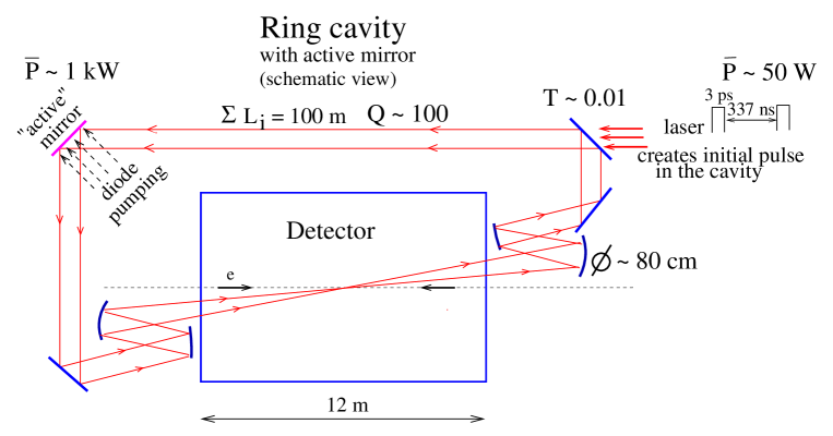
In the second scheme [15, 10, 26, 11], an “external” optical cavity is used. Using a train of low energy laser pulses one can create in the “external” cavity (with one mirror having small transmission) an optical pulse with an energy higher than in a laser pulse by a factor Q (cavity quality factor) and this pulse collides with electron bunches many times. As result the required laser power can be lower than in the one-pass case by factor of 50–100. Recently, I.Will [27] has suggested to place the final focusing mirrors outside the detector and added an “active” mirror to the optical cavity which should compensate attenuation of the laser pulse. Initial 5 J pulse in the cavity is created using a train of specially prepared pulses from the external laser (about 200 pulses, 0.05 J, 3 ps long, with frequencies matched to the cavity). Then this pulse is circulating in the optical ring cavity and losses of its intensity are compensated by an active mirror. Schematically this approach is illustrated in Fig.5. The optical scheme includes also (not shown) movable mirrors, adaptive optics, fast feedback. There are many questions to this scheme which need further study.
For NLC/JLC the train is short and the distance between electron bunches is only 2.8 ns therefore exploiting of the optical cavity is not effective. Small distance between electron bunches makes also a problem for combining pulses from several lasers to one train using Pockels cells. Current solution is the following. The laser system is based on about Mercury diode pumped lasers ( (Yb:S-FAP)) developed for the fusion program. The laser produces 100-200 J, several ns long pulses with 10 Hz rep. rate. Each pulse is split using semitransparent mirrors into 96 pulses with 2.8 ns delays and which then are compressed down to 2 ps using grating pairs. In this way one Mercury pulse is sufficient for production of one J pulse train for NLC photon collider. Twelve such lasers working sequentially are needed to provide 120 Hz rep. rate. The estimated cost of such laser “plant” according to the report at Snowmass2001 is of the order of 200 M$ [1].
This approach does not look optimum because only one Mercury laser of twelve is used in a given moment. This means, for example, that one need 12 independent diode-pumping systems which are very costly. It seems more reasonable to use about 5 special 30 J lasers which work in parallel with 120 Hz rep. rate. Each 30 J pulse is split in the same way as in [1] to twenty 1.5 J pulses, ten with vertical and ten with horizontal direction of linear polarization. Subtrains with equal polarization from all lasers are combined using Pockels cells and two long trains with perpendicular polarizations can be joined to one train using a thin film polarizer. Note that in this case the required switching time for Pockels cells is 33 ns which looks possible. The number of lasers and corresponding switching times can be optimized.
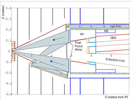
The optical system inside the detector for one NLC approach is shown in Fig.6 [1]. It is one pass laser scheme. The final focusing mirrors of 38 cm diameter are situated at the distance 4 m from the IP. The mirror has a hole with 15 cm diameter for incoming beams and outgoing disrupted beams.
Development of laser technologies is being driven by several large programs, such as inertial fusion. This is a fortunate situation for photon colliders as we may benefit from the laser technology developments of the last – years which cost hundreds M$ per year. In the last decade the technique of short pulse powerful solid state lasers made an impressive step and has reached petawatt () power levels and few femtosecond durations. Obtaining few joule pulses of picosecond duration is not a problem using modern laser techniques. The wave length of the most powerful lasers about 1 m which is just optimum for the TESLA Photon Collider.
5 Other experimental issues
5.1 Backgrounds
Photon colliders have one very specific background problem. High energy photon beams are produced just inside the detector. After the conversion the electron beams have a very broad spectrum, , and an angular spread of about 10 mrad which is due to deflection of the low energy particles by the opposing electron beam. In the case of head-on beam collisions large fraction of the beam would hit the final quadrupoles and produce enormous backgrounds in the detector. This problem is solved by using crab-crossing scheme of beam collisions [28, 7]. The maximum disruption angle for TESLA photon collider is about 12 mrad [11]. In the present design the crab-crossing angle in the photon collider IP is 34 mrad. These values put restriction on possible quadrupole design.
Other backgrounds are e+e- pairs and hadrons produced in beams collisions. Consideration of these and some other backgrounds can be found elsewhere [9, 29, 11]. QED background at photon colliders are very similar to e+e- collsions (or even smaller due to the large crab crossing angle and exit hole for disrupted beams. Strong longitudinal detector magnetic field confines low energy e+e- pairs near the collider axis and considerably reduce backgrounds in the vertex detector.
Some problem presents a hadronic background. The effective average rate of the reaction is about one event per bunch collisions. It can lead to some worsening of the resolution for jets at low angles [11].
6 Conclusion
As the ECFA Panel in Europe and the Snowmass Study and the HEPAP panel in US have recommended the linear collider on the energy about 500 GeV as the next large HEP project (Asian physicists have also similar plans), it is very likely that in about one decade physicists will get a new very powerful instrument for study of matter: e+e-, , e, e-e- collider.
The photon collider with , e collisions is very natural and technically feasible option for linear colliders. The physics potential of the photon collider is very rich and give information complementary to that in e+e- collisions. The next step in development of the photon collider, designing the second interaction region and detector needs active participation of experimentalists, detector physicists.
The work has been partially supported by the INTAS 00-00679 grant.
References
- [1] 2001 Report on the NLC submitted to Snowmass 2001, Fermilab-Conf 01-075, LBLL-47935, SLAC-R-571; Linear collider physics resource book for Snowmass 2001, By American Linear Collider Working Group (T. Abe et al.), SLAC-R-570, May 2001.
- [2] TESLA: The Superconducting electron positron linear collider with an integrated X-ray laser laboratory. Technical design report, DESY 2001-011, ECFA 2001-209, TESLA Report 2001-23, DESY-TESLA-FEL-2001-05, March 2001.
- [3] ACFA Linear Collider Working group (K.Abe et al.) KEK-REPORT-2001-11, hep-ph/0109166.
- [4] R. W. Assmann et al., “A 3-TeV e+e- linear collider based on CLIC technology,”, CERN-2000-008.
- [5] I. F. Ginzburg, G. L. Kotkin, V. G. Serbo, and V. I. Telnov, Pizma ZhETF, 34:514, 1981 (JETP Lett. 34:491, 1982); Nucl. Instrum. &Meth., 205:47, 1983.
- [6] I. F. Ginzburg, G. L. Kotkin, S. L. Panfil, V. G. Serbo, and V. I. Telnov. Nucl. Inst. Meth., A219:5, 1984.
- [7] V. I. Telnov, Nucl. Instrum. &Meth., A294:72, 1990.
- [8] V. I. Telnov, Nucl. Instrum. &Meth., A355:3, 1995.
- [9] R. Brinkmann et al., TESLA Conceptual Design, the Second Interaction Region for , e collisions, Nucl. Instrum. &Meth., A406:13, 1998, hep-ex/9707017.
- [10] V. Telnov, Nucl. Instr. &Meth. A472:43, 2001, hep-ex/0010033.
- [11] B. Badelek et al., TESLA Technical Design Report, Part VI, Ch.1. Photon collider at TESLA, DESY 2001-011, ECFA 2001-209, TESLA Report 2001-23, hep-ex/0108012.
- [12] I. Watanabe, et al, KEK-REPORT-97-17.
- [13] T. Takahashi, Nucl. Instr. &Meth. A472:4, 2001.
- [14] V. Telnov, H. Burkhardt, CERN-SL-2002-013-AP, CLIC-NOTE-508, 2002.
- [15] V. I. Telnov, Nucl. Phys. Proc. Suppl. 82:359, 2000, hep-ex/9908005.
- [16] V. Telnov, Int. J. Mod. Phys., A13:2399, 1998, hep-ex/9802003.
- [17] E. Boos et al., Nucl. Instr. &Meth. 472:100, 2001, hep-ph/0103090.
- [18] Proc. of Workshop on Colliders, Berkeley CA, USA, Nucl. Instrum. &Meth., A355, 1995.
-
[19]
Proc. International Workshop On High-Energy
Photon Colliders (GG2000), Hamburg, Germany, 2000.
Nucl. Instr. &Meth. A472 (2001).
http://www.desy.de/~gg2000/. - [20] M. Galynskii et al., Nucl. Instr. &Meth. A472:276, 2001, hep-ph/0012338.
- [21] D. Asner, J. Gronberg, J. Gunion, UCD-2001-8, hep-ph/0110320.
- [22] W. Decking, Nucl. Instr. &Meth. A472:297, 2001.
- [23] N. Walker, Nucl. Instr. &Meth. A472:291, 2001.
- [24] P. Raimondi and A. Seryi, SLAC-PUB-8460, Phys.Rev.Lett. 86:3779, 2001.
- [25] V. I. Telnov, In Workshop on Physics and Exper. with Linear e+e- Colliders, Waikoloa, USA, p. 323, 1993, World Scientific.
- [26] I. Will, T. Quast, H. Redlin, and W. Sandner, Nucl. Instr. &Meth. A472:79, 2001.
- [27] I. Will, Talk at ECFA-DESY workshop, Krakow, Poland, 14-18 September 2001.
- [28] R. B. Palmer, SLAC-PUB-4707.
- [29] V.I. Telnov, Proc. of 4th International Workshop on Linear Colliders (LCWS99), Sitges, Barcelona, Spain, 1999, DESY-TESLA-99-20D, hep-ex/9910010.