Recent Progress in Neutrino Factory and Muon Collider Research within the Muon Collaboration
Abstract
We describe the status of our effort to realize a first neutrino factory and the progress made in understanding the problems associated with the collection and cooling of muons towards that end. We summarize the physics that can be done with neutrino factories as well as with intense cold beams of muons. The physics potential of muon colliders is reviewed, both as Higgs Factories and compact high energy lepton colliders. The status and timescale of our research and development effort is reviewed as well as the latest designs in cooling channels including the promise of ring coolers in achieving longitudinal and transverse cooling simultaneously. We detail the efforts being made to mount an international cooling experiment to demonstrate the ionization cooling of muons.
pacs:
13.10.+q, 14.60.Ef, 29.27.-a, 29.20.DhI Introduction
Recent results from the SNO collaboration snolatest coupled with data from the SuperK collaboration superk have provided convincing evidence that neutrinos oscillate and that they very likely do so among the three known neutrino species. Experiments currently under way or planned in the near future will shed further light on the nature of these mixings among neutrino species and the magnitudes of the mass differences between them. Neutrino oscillations and the implied non-zero masses and mixings represent the first experimental evidence of effects beyond the Standard Model, and as such are worthy of vigorous scientific study.
This document indicates our progress along a path toward establishing an ongoing program of research in accelerator and experimental physics based on muon beams, and neutrino beams derived therefrom, that can proceed in an incremental fashion. At each step, new physics vistas open, leading eventually to a Neutrino Factory and possibly a Muon Collider. This concept has aroused significant interest throughout the world scientific community. In the U.S., a formal collaboration of some 110 scientists, the Neutrino Factory and Muon Collider Collaboration, also known as the Muon Collaboration (MC) EPP:collaboration , has undertaken the study of designing a Neutrino Factory, along with R&D activities in support of a Muon Collider design. The MC comprises three sponsoring national laboratories (BNL, FNAL, LBNL) along with groups from other U.S. national laboratories and universities and individual members from non-U.S. institutions.
One of the first steps toward a Neutrino Factory is a proton driver that can be used to provide intense beams of conventional neutrinos in addition to providing the intense source of low energy muons (from pion decay) that must first be “cooled” before being accelerated and stored. Our vision is that while a proton driver is being constructed, R&D on collecting and cooling muons would continue. A source of intense cold muons could be immediately used for physics measurements, such as determining the electric and magnetic dipole moments of the muon to higher precision, muonium-antimuonium oscillations, muon spin rotation experiments and rare muon decays. Once the capability of cooling and accelerating muons is fully developed, a storage ring for such muons would serve as the first Neutrino Factory. Its specific beam energy and its distance from the long-baseline experiment will be chosen using the knowledge of neutrino oscillation parameters gleaned from the present generation of solar and accelerator experiments (Homestake, Kamiokande, SuperKamiokande, SAGE, GALLEX, K2K, SNO), the next generation experiments (MiniBooNE, MINOS, CNGS, KamLAND, Borexino), and the high-intensity conventional beam experiments that would already have taken place.
A Neutrino Factory provides both and beams of equal intensity from a stored beam, and their charge-conjugate beams for a stored beam. Beams from a Neutrino Factory are intense compared with today’s neutrino sources. In addition, they have smaller divergence than conventional neutrino beams of comparable energy. These properties permit the study of non-oscillation physics at near detectors, and the measurement of structure functions and associated parameters in non-oscillation physics, to unprecedented accuracy. Likewise, they permit long-baseline experiments that can determine oscillation parameters to unprecedented accuracy.
Depending on the value of the parameter in the three-neutrino oscillation formalism, the oscillation is expected to be measurable. By comparing the rates for this channel with its charge-conjugate channel , the sign of the leading mass difference in neutrinos, , can be determined by observing the passage through matter of the neutrinos in a long-baseline experiment. Such experiments can also shed light on the CP-violating phase, , in the lepton mixing matrix and enable the study of CP violation in the lepton sector. (It is known that CP violation in the quark sector is insufficient to explain the baryon asymmetry of the Universe; lepton sector CP violation possibly played a crucial role in creating this asymmetry during the initial phases of the Big Bang.)
While the Neutrino Factory is being constructed, R&D aimed at making the Muon Collider a reality would be performed. The Muon Collider will require muon beams that are more intensely cooled and have generally more challenging properties than those for a Neutrino Factory, so the latter forms a practical goal en route to the former. A Muon Collider, if realized, provides a tool to explore Higgs-like objects by direct -channel fusion, much as LEP explored the . It also provides a potential means to reach higher energies (3–4 TeV in the center of mass) using relatively compact collider rings.
I.1 History
The concept of a Muon Collider was first proposed by Budker PREFACE:budker and by Skrinsky PREFACE:skrinsky in the 60s and early 70s. However, additional substance to the concept had to wait until the idea of ionization cooling was developed by Skrinsky and Parkhomchuk INTRO:ref3 . The ionization cooling approach was expanded by Neuffer INTRO:ref4 and then by Palmer PREFACE:palmer , whose work led to the formation of the Neutrino Factory and Muon Collider Collaboration (MC) EPP:collaboration in 1995111 A good summary of the Muon Collider concept can be found in the Status Report of 1999 INTRO:ref5 ; an earlier document INTRO:ref6 , prepared for Snowmass-1996, is also useful reading. MC Notes prepared by the Collaboration are available on the web INTRO:ref11 .
The concept of a neutrino source based on a pion storage ring was originally considered by Koshkarev INTRO:ref7 . However, the intensity of the muons created within the ring from pion decay was too low to provide a useful neutrino source. The Muon Collider concept provided a way to produce a very intense muon source. The physics potential of neutrino beams produced by high-intensity muon storage rings was briefly investigated in 1994 by King king94 and in more detail by Geer in 1997 at a Fermilab workshop rajageer ; geer where it became evident that the neutrino beams produced by muon storage rings needed for the Muon Collider were exciting in their own right. As a result, the MC realized that a Neutrino Factory could be an important first step toward a Muon Collider. With this in mind, the MC has shifted its primary emphasis toward the issues relevant to a Neutrino Factory. The Neutrino Factory concept quickly captured the imagination of the particle physics community, driven in large part by the exciting atmospheric neutrino deficit results from the SuperKamiokande experiment. The utility of non-oscillation neutrino physics from neutrinos produced by muon storage rings has been studied in detail from 1997 onwards non-osc .
There is also considerable international activity on Neutrino Factories, with international conferences held at Lyon in 1999 INTRO:ref13 , Monterey in 2000 INTRO:ref14 , Tsukuba in 2001 nufact01 , London in 2002 nufact02 and another planned in New York in 2003 nufact03 . There are also efforts in Europe europenf and Japan japannf to study different approaches to realizing the neutrino factory. Recently a proposal has been submitted to perform an International Muon Ionization Cooling Experiment (MICE) to the Rutherford Appleton Laboratory mice-prop .
I.2 Feasibility Studies
Complementing the MC experimental and theoretical R&D program, which includes work on targetry, cooling, rf hardware (both normal conducting and superconducting), high-field solenoids, liquid hydrogen absorber design, muon scattering experiments, theory, simulations, parameter studies, and emittance exchange INTRO:ref12 , the Collaboration has participated in several paper studies of a complete Neutrino Factory design.
In the fall of 1999, Fermilab, with help from the MC, undertook a Feasibility Study (“Study-I”) of an entry-level Neutrino Factory INTRO:ref1 . Study-I showed that the evolution of the Fermilab accelerator complex into a Neutrino Factory was clearly possible. The performance reached in Study-I, characterized in terms of the number of 50-GeV muon decays aimed at a detector located 3000 km away from the muon storage ring, was = 2 1019 decays per “Snowmass year” (107 s) per MW of protons on target.
Simultaneously, Fermilab launched a study of the physics that might be addressed by such a facility INTRO:ref9 and, more recently, initiated a study to compare the physics reach of a Neutrino Factory with that of conventional neutrino beams superbeams powered by a high-intensity proton driver (referred to as “superbeams”). As will be described later in this paper, a steady and diverse physics program will result from following the evolutionary path from a superbeam to a full-fledged Neutrino Factory.
Subsequently, BNL organized a follow-on study (“Study-II”) EPP:studyii on a high-performance Neutrino Factory, again in collaboration with the MC. Study-II demonstrated that BNL was likewise a suitable site for a Neutrino Factory. Based on the improvements in Study-II, the number of 20-GeV muon decays aimed at a detector located 3000 km away from the muon storage ring, was = 1.2 1020 decays per Snowmass year per MW of protons on target. Thus, with an upgraded 4 MW proton driver, the muon decay intensity would increase to 4.8 decays per Snowmass year. (R&D to develop a target capable of handling this beam power would be needed.) Though these numbers of neutrinos are potentially available for experiments, in the current storage-ring design the angular divergence at both ends of the production straight section is higher than desirable for the physics program. In any case, we anticipate that storage-ring designs are feasible that would allow 30–40% of the muon decays to provide useful neutrinos.
Both Study-I and -II are site specific in that each has a few site-dependent aspects; otherwise, they are generic. In particular, Study-I assumed a new Fermilab booster to achieve its beam intensities and an underground storage ring. Study-II assumed BNL site-specific proton driver specifications corresponding to an upgrade of the 24-GeV AGS complex and a BNL-specific layout of the storage ring, which is housed in an above-ground berm to avoid penetrating the local water table. The primary substantive difference between the two studies is that Study-II aimed at a lower muon energy (20 GeV), but higher intensity (for physics reach) than Study-I. Taking the two Feasibility Studies together, we conclude that a high-performance Neutrino Factory could easily be sited at either BNL or Fermilab. Figure 1 shows a comparison of the performance of the Neutrino Factory designs in Study-I and Study-II INTRO:ref9 with the physics requirements.
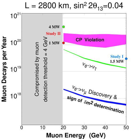
To put the above performance figures in context, it is important to note that a storage ring with an average neutrino energy of 15 GeV and useful muon decays would yield (in the absence of oscillations) 30,000 charged-current events in the channel per kiloton-year in a detector located 732 km away. In comparison, a 1.6 MW superbeam superbeams from the Fermilab Main Injector with an average neutrino energy of 15 GeV would yield only 13,000 charged-current events per kiloton-year. In addition to having lower intensity than a Neutrino Factory beam, a superbeam would have significant contamination, which will be the major background in appearance searches. That is, it will be much easier to detect the oscillation from a muon storage ring neutrino beam than to detect the oscillation from a conventional neutrino beam, because the electron final state from the conventional beam has significant background contribution from ’s produced in the events.
I.3 Neutrino Factory Description
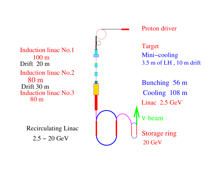
The muons we use result from decays of pions produced when an intense proton beam bombards a high-power production target. The target and downstream transport channel are surrounded by superconducting solenoids to contain the pions and muons, which are produced with a larger spread of transverse and longitudinal momenta than can be conveniently transported through an acceleration system. To prepare a beam suitable for subsequent acceleration, we first perform a “phase rotation,” during which the initial large energy spread and small time spread are interchanged using induction linacs. Next, to reduce the transverse momentum spread, the resulting long bunch, with an average momentum of about 250 MeV/c, is bunched into a 201.25-MHz bunch train and sent through an ionization cooling channel consisting of LH2 energy absorbers interspersed with rf cavities to replenish the energy lost in the absorbers. The resulting beam is then accelerated to its final energy using a superconducting linac to make the beam relativistic, followed by one or more recirculating linear accelerators (RLAs). Finally, the muons are stored in a racetrack-shaped ring with one long straight section aimed at a detector located at a distance of roughly 3000 km. A schematic layout is shown in Fig. 2.
I.4 Detector
Specifications for the long-baseline Neutrino Factory detector are rather typical for an accelerator-based neutrino experiment. However, because of the need to maintain a high neutrino rate at these long distances (3000 km), the detectors considered here are 3–10 times more massive than those in current neutrino experiments.
Several detector options could be considered for the far detector:
For the near detector, a compact liquid-argon TPC (similar to the ICARUS detector ICARUS ) could be used. An experiment with a relatively thin Pb target (1 ), followed by a standard fixed-target spectrometer could also be considered.
I.5 Staging Scenario
If desired by the particle physics community, a fast-track plan leading directly to a Neutrino Factory could be executed. On the other hand, the Neutrino Factory offers the distinct advantage that it can be built in stages. This could satisfy both programmatic and cost constraints by allowing an ongoing physics program while reducing the annual construction funding needs. Depending on the results of our technical studies and the results of ongoing searches for the Higgs boson, it is hoped that the Neutrino Factory is really the penultimate stage, to be followed later by a Muon Collider (e.g., a Higgs Factory). Such a collider offers the potential of bringing the energy frontier in particle physics within reach of a moderate-sized machine. Possible stages for the evolution of a muon beam facility are described in Section III.10.
I.6 R&D Program
Successful construction of a muon storage ring to provide a copious source of neutrinos requires development of many novel approaches; construction of a high-luminosity Muon Collider requires even more. It was clear from the outset that the breadth of R&D issues to be dealt with would be beyond the resources available at any single national laboratory or university. For this reason, in 1995, interested members of the high-energy physics and accelerator physics communities formed the MC to coordinate the required R&D efforts nationally. The task of the MC is to define and carry out R&D needed to assess the technical feasibility of constructing initially a muon storage ring that will provide intense neutrino beams aimed at detectors located many thousands of kilometers from the accelerator site, and ultimately a collider that will carry out fundamental experiments at the energy frontier in high-energy physics.
The MC also serves to coordinate muon-related R&D activities of the NSF-sponsored University Consortium (UC) and the state-sponsored Illinois Consortium for Accelerator Research (ICAR), and is the focal point for defining the needs of muon-related R&D to the managements of the sponsoring national laboratories and to the funding agencies (both DOE and NSF). As already noted, though the MC was formed initially to carry out R&D that might lead eventually to the construction of a Muon Collider, more recently its focus has shifted mainly, but not exclusively, to a Neutrino Factory.
The MC maintains close contact with parallel R&D efforts under way in Europe (centered at CERN) and in Japan (centered at KEK). Through its international members, the MC also fosters coordination of the international muon-beam R&D effort. Two major initiatives, a Targetry Experiment (E951) in operation at BNL and a Muon Cooling R&D program (MUCOOL), have been launched by the MC. In addition, the Collaboration, working in conjunction with the UC and ICAR in some areas, coordinates substantial efforts in accelerator physics and component R&D to define and assess parameters for feasible designs of muon-beam facilities.
I.7 Outline of Report
In what follows, we give the motivation and a scenario for a staged approach to constructing a Neutrino Factory and eventually a Muon Collider. Section II discusses the physics opportunities, starting from conventional “superbeams” and going to cold muon beams, then a Neutrino Factory with its near and far detectors, and finally a Muon Collider. In Section III, we describe the components of a Neutrino Factory, based on the Study-II design, and indicate a scientifically productive staged path for reaching it. Section IV covers our present concept of an entry-level Higgs Factory Muon Collider. In support of the construction of a Neutrino Factory, an R&D program is already under way to address various technical issues. A description of the status and plans for this program is presented in Section V. Section VI describes current thinking about a cooling demonstration experiment that would be carried out as an international effort. Finally, in Section VII we provide a brief summary of our work.
II Physics Motivation
In this Section we cover the physics potential of the Neutrino Factory accelerator complex, which includes superbeams of conventional neutrinos that are possible using the proton driver needed for the factory, and intense beams of cold muons that become available once the muon cooling and collection systems for the factory are in place. Once the cold muons are accelerated and stored in the muon storage ring, we realize the full potential of the factory in both neutrino oscillation and non-oscillation physics. Cooling muons will be a learning experience. We hope that the knowledge gained in constructing a Neutrino Factory can be used to cool muons sufficiently to produce the first muon collider operating as a Higgs factory. We examine the physics capabilities of such a collider, which if realized, will invariably lead to higher energy muon colliders with exciting physics opportunities.
II.1 Neutrino Oscillation Physics
Here we discuss study2 the current evidence for neutrino oscillations, and hence neutrino masses and lepton mixing, from solar and atmospheric data. A review is given of some theoretical background including models for neutrino masses and relevant formulas for neutrino oscillation transitions. We next mention the near-term and mid-term experiments in this area and comment on what they hope to measure. We then discuss the physics potential of a muon storage ring as a Neutrino Factory in the long term.
II.1.1 Evidence for Neutrino Oscillations
In a modern theoretical context, one generally expects nonzero neutrino masses and associated lepton mixing. Experimentally, there has been accumulating evidence for such masses and mixing. All solar neutrino experiments (Homestake, Kamiokande, SuperKamiokande, SAGE, GALLEX and SNO) show a significant deficit in the neutrino fluxes coming from the Sun sol . This deficit can be explained by oscillations of the ’s into other weak eigenstate(s), with of the order eV2 for solutions involving the Mikheyev-Smirnov-Wolfenstein (MSW) resonant matter oscillations wolf –ms or of the order of eV2 for vacuum oscillations just-so . Accounting for the data with vacuum oscillations (VO) requires almost maximal mixing. The MSW solutions include one for small mixing angle (SMA) and one for large mixing angle (LMA). Another piece of evidence for neutrino oscillations is the atmospheric neutrino anomaly, observed by Kamiokande kam , IMB imb , SuperKamiokande sk with the highest statistics, and by Soudan soudan2 and MACRO macro . These data can be fit by the inference of oscillations with sk and maximal mixing . The identification is preferred over , and the identification is excluded by both the Superkamiokande data and the Chooz experiment chooz . In addition, the LSND experiment lsnd has reported and oscillations with and a range of possible mixing angles. This result is not confirmed, but also not completely ruled out, by a similar experiment, KARMEN karmen . The miniBOONE experiment at Fermilab is designed to resolve this issue, as discussed below. If one were to try to fit all of these experiments, then, since they involve three quite different values of , which could not satisfy the identity for three neutrino species,
| (1) |
it would follow that one would have to introduce at least one further neutrino. Since it is known from the measurement of the width that there are only three leptonic weak doublets with associated light neutrinos, it follows that such further neutrino weak eigenstate(s) would have to be electroweak singlet(s) (“sterile” neutrinos). Because the LSND experiment has not been confirmed by the KARMEN experiment, we choose here to use only the (confirmed) solar and atmospheric neutrino data in our analysis, and hence to work in the context of three active neutrino weak eigenstates.
II.1.2 Neutrino Oscillation Formalism
In this theoretical context, consistent with solar and atmospheric data, there are three electroweak-doublet neutrinos and the neutrino mixing matrix is described by
| (2) |
where , , and . The phases and do not affect neutrino oscillations. Thus, in this framework, the neutrino mixing relevant for neutrino oscillations depends on the four angles , , , and , and on two independent differences of squared masses, , which is in the favored fit, and , which may be taken to be . Note that these quantities involve both magnitude and sign; although in a two-species neutrino oscillation in vacuum the sign does not enter, in the three-species-oscillation, which includes both matter effects and violation, the signs of the quantities enter and can, in principle, be measured. For our later discussion it will be useful to record the formulas for the various neutrino-oscillation transitions. In the absence of any matter effect, the probability that a (relativistic) weak neutrino eigenstate becomes after propagating a distance is
| (3) | |||||
where
| (4) |
and
| (5) |
Recall that in vacuum, invariance implies and hence, for , . For the CP-transformed reaction and the T-reversed reaction , the transition probabilities are given by the right-hand side of (3) with the sign of the imaginary term reversed. (Below we shall assume invariance, so that violation is equivalent to violation.) In most cases there is only one mass scale relevant for long-baseline neutrino oscillations, , and one possible neutrino mass spectrum is the hierarchical one
| (6) |
In this case, violation effects may be negligibly small, so that in vacuum
| (7) |
and
| (8) |
In the absence of violation, the second equality (8) would still hold in uniform matter, but even in the absence of violation, the first equality (7) would not hold. With the hierarchy (6), the expressions for the specific oscillation transitions are
| (9) | |||||
| (10) | |||||
| (11) | |||||
In neutrino oscillation searches using reactor antineutrinos, i.e, tests of , the two-species mixing hypothesis used to fit the data is
| (12) | |||||
where is the squared mass difference relevant for . In particular, in the upper range of values of , since the transitions and contribute to disappearance, one has
| (13) |
i.e., , and, for the value from SuperK, the CHOOZ experiment on disappearance yields the upper limit chooz
| (14) |
which is also consistent with conclusions from the SuperK data analysis sk . Further, the quantity “” often used to fit the data on atmospheric neutrinos with a simplified two-species mixing hypothesis, is, in the three-generation case,
| (15) |
The SuperK experiment finds that the best fit to their data is oscillations with maximal mixing, and hence and . The various solutions of the solar neutrino problem involve quite different values of and : (i) large mixing angle solution, LMA: and ; (ii) small mixing angle solution, SMA: and , (iii) LOW: , , and (iv) “just-so”: , . The SuperK experiment favors the LMA solutions sol ; for other global fits, see, e.g., Ref. sol . We have reviewed the three neutrino oscillation phenomenology that is consistent with solar and atmospheric neutrino oscillations. In what follows, we will examine the neutrino experiments planned for the immediate future that will address some of the relevant physics. We will then review the physics potential of the Neutrino Factory.
II.1.3 Relevant Near- and Mid-Term Experiments
There are currently intense efforts to confirm and extend the evidence for neutrino oscillations in all of the various sectors — solar, atmospheric, and accelerator. Some of these experiments are running; in addition to SuperKamiokande and Soudan-2, these include the Sudbury Neutrino Observatory, SNO, and the K2K long baseline experiment between KEK and Kamioka. Others are in development and testing phases, such as miniBOONE, MINOS, the CERN–Gran Sasso program, KamLAND, Borexino, and MONOLITH anl . Among the long baseline neutrino oscillation experiments, the approximate distances are km for K2K, 730 km for both MINOS (from Fermilab to Soudan) and the proposed CERN–Gran Sasso experiments. K2K is a disappearence experiment with a conventional neutrino beam having a mean energy of about 1.4 GeV, going from KEK 250 km to the SuperK detector. It has a near detector for beam calibration. It has obtained results consistent with the SuperK experiment, and has reported that its data disagree by with the no-oscillation hypothesis k2k . MINOS is another conventional neutrino beam experiment that takes a beam from Fermilab 730 km to a detector in the Soudan mine in Minnesota. It again uses a near detector for beam flux measurements and has opted for a low-energy configuration, with the flux peaking at about 3 GeV. This experiment is scheduled to start taking data in 2005 and, after some years of running, to obtain higher statistics than the K2K experiment and to achieve a sensitivity down to the level . The CERN–Gran Sasso program will also come on in 2005. It will use a higher-energy neutrino beam, GeV, from CERN to the Gran Sasso deep underground laboratory in Italy. This program will emphasize detection of the ’s produced by the ’s that result from the inferred neutrino oscillation transition . The OPERA experiment will do this using emulsions opera , while the ICARUS proposal uses a liquid argon chamber icanoe . For the joint capabilities of MINOS, ICARUS and OPERA experiments see Ref. minicop . Plans for the Japan Hadron Facility (JHF), also called the High Intensity Proton Accelerator (HIPA), include the use of a 0.77 MW proton driver to produce a high-intensity conventional neutrino beam with a path length of 300 km to the SuperK detector jhf . Moreover, at Fermilab, the miniBOONE experiment is scheduled to start data taking in the near future and to confirm or refute the LSND claim after a few years of running. There are several neutrino experiments relevant to the solar neutrino anomaly. The SNO experiment is currently running and has recently reported their first results that confirm solar neutrino oscillations snolatest . These involve measurement of the solar neutrino flux and energy distribution using the charged current reaction on heavy water, . They are expected to report on the neutral current reaction shortly. The neutral current rate is unchanged in the presence of oscillations that involve standard model neutrinos, since the neutral current channel is equally sensitive to all the three neutrino species. If however, sterile neutrinos are involved, one expects to see a depletion in the neutral current channel also. However, the uncertain normalization of the 8B flux makes it difficult to constrain a possible sterile neutrino component in the oscillations unknowns . The KamLAND experiment kamland in Japan started taking data in January 2002. This is a reactor antineutrino experiment using baselines of 100–250 km. It will search for disappearance and is sensitive to the solar neutrino oscillation scale. KamLAND can provide precise measurements of the LMA solar parameters bmw-kamland and recently the first results from KamLAND have confirmed the LMA solution kamland1 . A global analysis of the KamLAND and solar neutrino data has further restricted the solar range and the best fit value currently is eV2 bargermarf ; fogli . On a similar time scale, the Borexino experiment in Gran Sasso is scheduled to turn on and measure the 7Be neutrinos from the sun. These experiments should help us determine which of the various solutions to the solar neutrino problem is preferred, and hence the corresponding values of and . This, then, is the program of relevant experiments during the period 2000–2010. By the end of this period, we may expect that much will be learned about neutrino masses and mixing. However, there will remain several quantities that will not be well measured and which can be measured by a Neutrino Factory.
II.1.4 Oscillation Experiments at a Neutrino Factory
Although a Neutrino Factory based on a muon storage ring will turn on several years after this near-term period in which K2K, MINOS, and the CERN-Gran Sasso experiments will run, it has a valuable role to play, given the very high-intensity neutrino beams of fixed flavor-pure content, including, uniquely, and beams in addition to and beams. A conventional positive charge selected neutrino beam is primarily with some admixture of ’s and other flavors from decays (O(1%) of the total charged current rate) and the fluxes of these neutrinos can only be fully understood after measuring the charged particle spectra from the target with high accuracy. In contrast, the potential of the neutrino beams from a muon storage ring is that the neutrino beams would be of extremely high purity: beams would yield 50% and 50% , and beams, the charge conjugate neutrino beams. Furthermore, these could be produced with high intensities and low divergence that make it possible to go to longer baselines.
In what follows, we shall take the design values from Study-II of decays per “Snowmass year” ( sec) as being typical. The types of neutrino oscillations that can be searched for with the Neutrino Factory based on the muon storage ring are listed in Table 1 for the case of which decays to :
| Conventional | Neutrino | ||
| Measurement | Type | beam | Factory |
| survival | * | ||
| appearance | |||
| appearance | |||
| survival | — | ||
| appearance | — | ||
| appearance | — |
It is clear from the processes listed that since the beam contains both neutrinos and antineutrinos, the only way to determine the flavor of the parent neutrino is to determine the identity of the final state charged lepton and measure its charge. A capability unique to the Neutrino Factory will be the measurement of the oscillation , giving a wrong-sign . Of greater difficulty would be the measurement of the transition , giving a which will decay part of the time to . These physics goals mean that a detector must have excellent capability to identify muons and measure their charges. Especially in a steel-scintillator detector, the oscillation would be difficult to observe, since it would be difficult to distinguish an electron shower from a hadron shower. From the above formulas for oscillations, one can see that, given the knowledge of and that will be available by the time a Neutrino Factory is built, the measurement of the transition yields the value of . To get a rough idea of how the sensitivity of an oscillation experiment would scale with energy and baseline length, recall that the event rate in the absence of oscillations is simply the neutrino flux times the cross section. First of all, neutrino cross sections in the region above about 10 GeV (and slightly higher for production) grow linearly with the neutrino energy. Secondly, the beam divergence is a function of the initial muon storage ring energy; this divergence yields a flux, as a function of , the angle of deviation from the forward direction, that goes like . Combining this with the linear dependence of the neutrino cross section and the overall dependence of the flux far from the production region, one finds that the event rate goes like
| (16) |
We base our discussion on the event rates given in the Fermilab Neutrino Factory study INTRO:ref9 . For a stored muon energy of 20 GeV, and a distance of to the WIPP Carlsbad site in New Mexico, these event rates amount to several thousand events per kton of detector per year, i.e, they are satisfactory for the physics program. This is also true for the other path lengths under consideration, namely km from BNL to Homestake and km to Soudan. A usual racetrack design would only allow a single pathlength , but a bowtie design could allow two different path lengths (e.g., zp ). We anticipate that at a time when the Neutrino Factory turns on, and would be known at perhaps the 10% level (while recognizing that future projections such as this are obviously uncertain). The Neutrino Factory will significantly improve precision in these parameters, as can be seen from Fig. 3 which shows the error ellipses possible for a 30 GeV muon storage ring.

In addition, the Neutrino Factory can contribute to the measurement of: (i) , as discussed above; (ii) measurement of the sign of using matter effects; and (iii) possibly a measurement of violation in the leptonic sector, if , , and are sufficiently large. To measure the sign of , one uses the fact that matter effects reverse sign when one switches from neutrinos to antineutrinos, and carries out this switch in the charges of the stored . We elaborate on this next.
II.1.5 Matter Effects
With the advent of the muon storage ring, the distances at which one can place detectors are large enough so that for the first time matter effects can be exploited in accelerator-based oscillation experiments. Simply put, matter effects are the matter-induced oscillations that neutrinos undergo along their flight path through the Earth from the source to the detector. Given the typical density of the earth, matter effects are important for the neutrino energy range GeV and eV2, values relevant for the long baseline experiments. Matter effects in neutrino propagation were first pointed out by Wolfenstein wolf and Barger, Pakvasa, Phillips and Whisnant bppw-1980 . (See the papers dgh –cpv for details of the matter effects and their relevance to neutrino factories.) In brief, assuming a normal hierarchy, the transition probabilities for propagation through matter of constant density are golden ; formcon
| (17) | |||||
| (18) | |||||
where
| (20) | |||||
| (21) | |||||
| (22) | |||||
| (23) | |||||
| (24) | |||||
| (25) | |||||
| (26) |
The amplitude for forward scattering in matter is given by
| (27) |
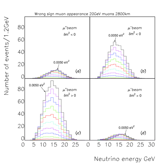
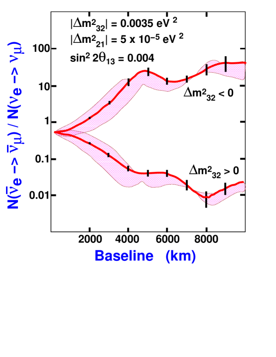
Here is the electron fraction and is the matter density. For neutrino trajectories that pass through the earth’s crust, the average density is typically of order 3 gm/cm3 and . For neutrinos with or anti-neutrinos with , corresponds to a matter resonance. Thus, for a Neutrino Factory operating with positive stored muons (producing a beam) one expects an enhanced production of opposite sign () charged-current events as a result of the oscillation if is positive and vice versa for stored negative beams. Figure 4 barger-raja shows the wrong-sign muon appearance spectra as function of for both and beams for both signs of at a baseline of 2800 km. The resonance enhancement in wrong sign muon production is clearly seen in Fig. 4(b) and (c).
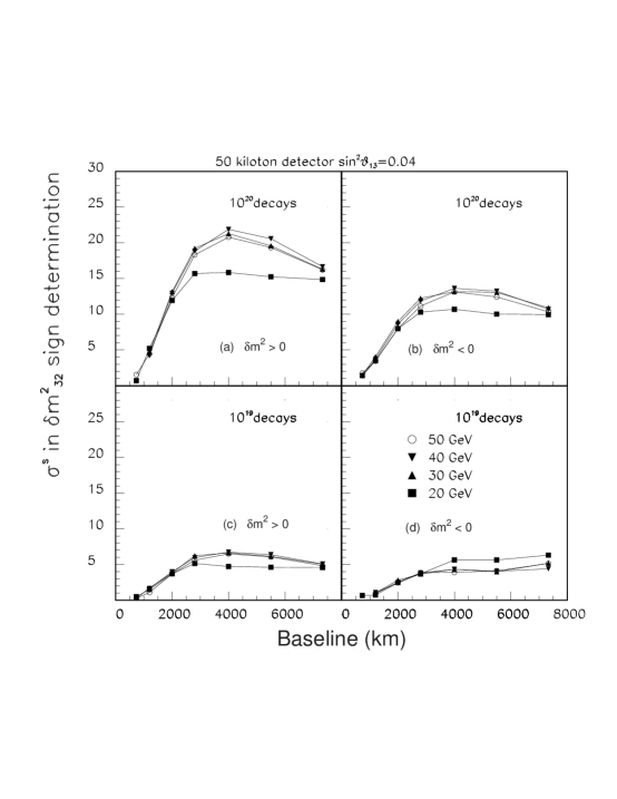
By comparing these (using first a stored beam and then a stored beam) one can thus determine the sign of as well as the value of . Figure 5 barger-raja shows the difference in negative log-likelihood between a correct and wrong-sign mass hypothesis expressed as a number of equivalent Gaussian standard deviations versus baseline length for muon storage ring energies of 20, 30, 40 and 50 GeV. The values of the oscillation parameters are for the LMA scenario with . Figure 5(a) is for 1020 decays for each sign of stored energy and a 50 kiloton detector and positive , (b) is for negative for various values of stored muon energy. Figures 5 (c) and (d) show the corresponding curves for 1019 decays and a 50 kiloton detector. An entry-level machine would permit one to perform a 5 differentiation of the sign of at a baseline length of 2800 km.
For the Study II design, in accordance with the previous Fermilab study INTRO:ref9 , one estimates that it is possible to determine the sign of even if is as small as .
II.1.6 CP Violation
violation is measured by the (rephasing-invariant) product
| (28) | |||||
| (30) |
Leptonic CP violation also requires that each of the leptons in each charge sector be nondegenerate with any other leptons in this sector; this is, course, true of the charged lepton sector and, for the neutrinos, this requires for each such pair . In the quark sector, is known to be small: . A promising asymmetry to measure is . As an illustration, in the absence of matter effects,
| (31) | |||||
| (32) |
where
| (33) |
In order for the violation in Eq. (32) to be large enough to measure, it is necessary that , , and not be too small. From atmospheric neutrino data, we have and . If LMA describes solar neutrino data, then , so . For example, if , then could be . Furthermore, for parts of the LMA phase space where eV2 the CP violating effects might be observable. In the absence of matter, one would measure the asymmetry
| (34) |
However, in order to optimize this ratio, because of the smallness of even for the LMA, one must go to large pathlengths , and here matter effects are important. These make leptonic violation challenging to measure, because, even in the absence of any intrinsic violation, these matter effects render the rates for and unequal since the matter interaction is opposite in sign for and . One must therefore subtract out the matter effects in order to try to isolate the intrinsic violation. Alternatively, one might think of comparing with the time-reversed reaction . Although this would be equivalent if is valid, as we assume, and although uniform matter effects are the same here, the detector response is quite different and, in particular, it is quite difficult to identify . Results from SNO and KamLAND testing the LMA bmw-kamland will help further planning. The Neutrino Factory provides an ideal set of controls to measure violation effects since we can fill the storage ring with either or particles and measure the ratio of the number of events /. Figure 6 shows this ratio for a Neutrino Factory with 1021 decays and a 50 kiloton detector as a function of the baseline length. The ratio depends on the sign of . The shaded band around either curve shows the variation of this ratio as a function of the -violating phase . The number of decays needed to produce the error bars shown is directly proportional to , which for the present example is set to 0.004. Depending on the magnitude of , one may be driven to build a Neutrino Factory just to understand violation in the lepton sector, which could have a significant role in explaining the baryon asymmetry of the Universe yanag .
II.2 Physics Potential of Superbeams
It is possible to extend the reach of the current conventional neutrino experiments by enhancing the capabilities of the proton sources that drive them. These enhanced neutrino beams have been termed “superbeams” and form an intermediate step on the way to a Neutrino Factory. Their capabilities have been explored in recent papers superbeams ; bargersuperbeam ; superbeam-peak . These articles consider the capabilities of enhanced proton drivers at (i) the proposed 0.77 MW 50 GeV proton synchrotron at the Japan Hadron Facility (JHF) jhf , (ii) a 4 MW upgraded version of the JHF, (iii) a new MW 16 GeV proton driver brighter that would replace the existing 8 GeV Booster at Fermilab, or (iv) a fourfold intensity upgrade of the 120 GeV Fermilab Main Injector (MI) beam (to 1.6 MW) that would become possible once the upgraded (16 GeV) Booster was operational. Note that the 4 MW 50 GeV JHF and the 16 GeV upgraded Fermilab Booster are both suitable proton drivers for a neutrino factory. The conclusions of both reports are that superbeams will extend the reaches in the oscillation parameters of the current neutrino experiments but “the sensitivity at a Neutrino Factory to violation and the neutrino mass hierarchy extends to values of the amplitude parameter that are one to two orders of magnitude lower than at a superbeam” bargersuperbeam ; superbeam-peak .
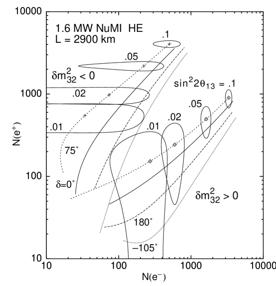
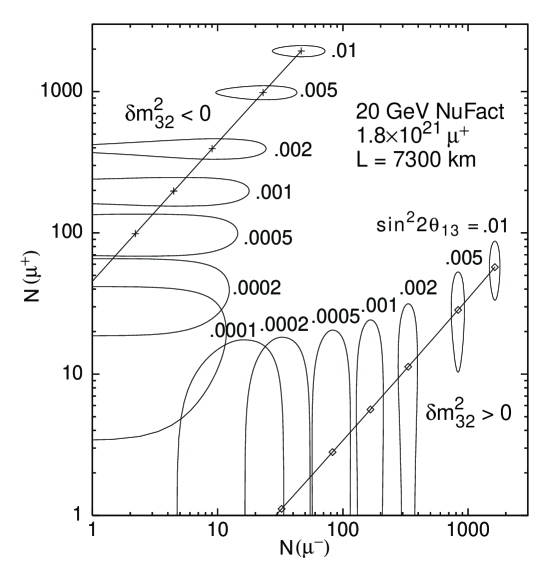
To illustrate these points, we choose one of the most favorable superbeam scenarios studied: a 1.6 MW NuMI-like high energy beam with km, detector parameters corresponding to the liquid argon scenario in bargersuperbeam ; superbeam-peak , and oscillation parameters eV2 and eV2. The calculated three-sigma error ellipses in the plane are shown in Fig. 7 for both signs of , with the curves corresponding to various phases (as labeled). The magnitude of the oscillation amplitude parameter varies along each curve, as indicated. The two groups of curves, which correspond to the two signs of , are separated by more than provided . Hence the mass heirarchy can be determined provided the oscillation amplitude is not more than an order of magnitude below the currently excluded region. Unfortunately, within each group of curves, the -conserving predictions are separated from the maximal -violating predictions by at most . Hence, it will be difficult to conclusively establish violation in this scenario. Note for comparison that a very long baseline experiment at a neutrino factory would be able to observe oscillations and determine the sign of for values of as small as . This is illustrated in Fig. 8. A Neutrino Factory thus outperforms a conventional superbeam in its ability to determine the sign of . Comparing Fig. 7 and Fig. 8 one sees that the value of , which has yet to be measured, will determine the parameters of the first Neutrino Factory.
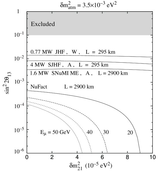
Finally, we compare the superbeam reach with the corresponding Neutrino Factory reach in Fig. 9, which shows the sensitivity contours in the plane. The superbeam reach of a few is almost independent of the sub-leading scale . However, since the neutrino factory probes oscillation amplitudes the sub-leading effects cannot be ignored, and events would be observed at a Neutrino Factory over a significant range of even if .
II.3 Non-oscillation physics at a Neutrino Factory
The study of the utility of intense neutrino beams from a muon storage ring in determining the parameters governing non-oscillation physics was begun in 1997 rajageer . More complete studies can be found in INTRO:ref9 and recently a European group has brought out an extensive study on this topic cern-nonosc . A Neutrino Factory can measure individual parton distributions within the proton for all light quarks and anti-quarks. It could improve valence distributions by an order of magnitude in the kinematical range in the unpolarized case. The individual components of the sea (, , and ), as well as the gluon, would be measured with relative accuracies in the range of 1–10%, for . A full exploitation of the Neutrino Factory potential for polarized measurements of the shapes of individual partonic densities requires an a priori knowledge of the polarized gluon density. The forthcoming set of polarized deep inelastic scattering experiments at CERN, DESY and RHIC may provide this information. The situation is also very bright for measurements of -even distributions. Here, the first moments of singlet, triplet and octet axial charges can be measured with accuracies that are up to one order of magnitude better than the current uncertainties. In particular, the improvement in the determination of the singlet axial charge would allow a definitive confirmation or refutation of the anomaly scenario compared to the ‘instanton’ or ‘skyrmion’ scenarios, at least if the theoretical uncertainty originating from the small- extrapolation can be kept under control. The measurement of the octet axial charge with a few percent uncertainty will allow a determination of the strange contribution to the proton spin better than 10%, and allow stringent tests of models of violation when compared to the direct determination from hyperon decays. A measurement of and will involve different systematics from current measurements and will therefore provide an important consistency check of current data, although the accuracy of these values is not expected to be improved. The weak mixing angle can be measured in both the hadronic and leptonic modes with a precision of approximately , dominated by the statistics and the luminosity measurement. This determination would be sensitive to different classes of new-physics contributions. Neutrino interactions are a very good source of clean, sign-tagged charm particles. A Neutrino Factory can measure charm production with raw event rates up to 100 million charm events per year with 2 million double-tagged events. (Note that charm production becomes significant for storage ring energies above 20 GeV). Such large samples are suitable for precise extractions of branching ratios and decay constants, the study of spin-transfer phenomena, and the study of nuclear effects in deep inelastic scattering. The ability to run with both hydrogen and heavier targets will provide rich data sets useful for quantitative studies of nuclear models. The study of polarization both in the target and in the fragmentation regions will help clarify the intriguing problem of spin transfer.
Although the neutrino beam energies are well below any reasonable threshold for new physics, the large statistics makes it possible to search for physics beyond the Standard Model. The high intensity neutrino beam allows a search for the production and decay of neutral heavy leptons with mixing angle sensitivity two orders of magnitude better than present limits in the 30–80 MeV range. The exchange of new gauge bosons decoupled from the first generation of quarks and leptons can be seen via enhancements of the inclusive charm production rate, with a sensitivity well beyond the present limits. A novel neutrino magnetic moment search technique that uses oscillating magnetic fields at the neutrino beam source could discover large neutrino magnetic moments predicted by some theories. Rare lepton-flavor-violating decays of muons in the ring could be tagged in the deep inelastic scattering final states through the detection of wrong-sign electrons and muons, or of prompt taus.
II.4 Physics that can be done with Intense Cold Muon Beams
Experimental studies of muons at low and medium energies have had a long and distinguished history, starting with the first search for muon decay to electron plus gamma-ray Hincks-Pontecorvo , and including along the way the 1957 discovery of the nonconservation of parity, in which the value and magnetic moment of the muon were first measured Garwinetal . The years since then have brought great progress: limits on the standard-model-forbidden decay have dropped by nine orders of magnitude, and the muon anomalous magnetic moment has yielded one of the more precise tests ( ppm) of physical theory BNLg-2 . The front end of a Neutrino Factory has the potential to provide muons per year, five orders of magnitude beyond the most intense beam currently available222The E5 beam at PSI, Villigen, providing a maximum rate of muons/s Edgecock ..
Such a facility could enable a rich variety of precision measurements. In the area of low energy muon physics a majority of experiments with a high physics potential is limited at present by statistics. The list of conceivable projects includes (see Table 2):
-
•
precise determinations of the properties characterizing the muon, which are the mass , magnetic moment , magnetic anomaly , charge and lifetime ,
-
•
measurements the muon decay parameters (Michel parameters),
-
•
CPT tests from a comparison of and properties,
-
•
measurements of fundamental constants of general importance (e.g. the electromagnetic fine structure constant or the weak interaction Fermi constant )
-
•
sensitive searches for physics beyond the Standard Model either through measuring differences of muon parameters from Standard Model predictions or in dedicated searches for rare and forbidden processes, such as , , conversion and muonium-antimuonium () conversion or searches for a permanent electric dipole moment of the particle,
-
•
searches for and violation in muonic atoms,
-
•
precise determinations of nuclear properties in muonic (radioactive) atoms,
-
•
applications in condensed matter, thin films and at surfaces,
-
•
applications in life sciences, and
-
•
muon catalyzed fusion(CF).
A detailed evaluation of the possibilities has recently been made by a CERN study group, which assumed a facility with a 4 MW proton driverAysto_01 .
In the search for “forbidden” decays, Marciano Marciano97 has suggested that muon Lepton Flavor Violation (LFV) (especially coherent muon-to-electron conversion in the field of a nucleus) is the “best bet” for discovering signatures of new physics using low-energy muons. The MECO experiment MECO proposed at BNL offers, through a novel detector concept, very high sensitivity and some four orders of magnitude improvement over the current limits from PSI SINDRUM . At a future high muon flux facility, such as the Neutrino Factory, this could be improved further by 1-2 orders of magnitude.
The search for is also of great interest. The MEGA experiment recently set an upper limit MEGA . Ways to extend sensitivity to the level have not only been discussed Cooper97 but also have lead to an active proposal at PSI Mori_99 . The experiment aims for an improvement of three orders of magnitude over MEGA which had systematics limitations. The -to--conversion approach has the additional virtue of sensitivity to new physics that does not couple to the photon.
An observation of a non-zero Electric Dipole Moment (EDM) of the muon, , could prove equally exciting; This has generated a Letter of Intent EDMLOI to observe , which proposes to use the the large electric fields associated with relativistic particles in a magnetic storage ring. As CP violation enters in the quark sector starting with the second generation, the muon is a particularly valuable probe in this regard, despite the already low limits for electrons. Moreover, there exist some models in which the electric dipole moment scales stronger than linearlyEllis_01 .
It is worth noting that for searches of rare muon decays and for that the standard model predictions are orders of magnitude below the presently established limits. Any observation which can be shown to be not an artefact of the experimental method or due to background would therefore be a direct sign of new physics.
There are three experiments going on currently to improve the muon lifetime tau_mu . Note that the Fermi coupling constant is derived from a measurement of . The efforts are therefore worthwhile whenever experimental conditions allow substantial improvement. One should however be aware that a comparison with theory in this channel is presently dominated by theoretical uncertainties.
In the case of precision measurements (, , etc.), new-physics effects appear as small corrections arising from the virtual exchange of new massive particles in loop diagrams. In contrast, LFV and EDMs are forbidden in the standard model, thus their observation at any level would constitute evidence for new physics.
| Type of Experiment | Physics Issues |
|
||||||||||||||||
|---|---|---|---|---|---|---|---|---|---|---|---|---|---|---|---|---|---|---|
| “Classical” rare & forbidden decays | Lepton number violation; searches for new physics: SUSY, L-R Symmetry, R-parity violation,… |
|
||||||||||||||||
| Muon Decays | ; searches for new physics; Michel parameters |
|
||||||||||||||||
| Muon Moments | Standard model tests; new physics; CPT tests T- resp. CP-violation in 2nd lepton generation |
|
||||||||||||||||
| Muonium Spectroscopy | Fundamental constants, , , ; weak interactions; muon charge |
|
||||||||||||||||
| Muonic Atoms | Nuclear charge radii; weak interactions |
|
||||||||||||||||
| Condensed Matter | surfaces, catalysis, bio sciences… |
|
| Experiment | |||||||
| [ns] | [ns] | [MeV] | [%] | ||||
| – | 1…5 | ||||||
| + | n/a | continuous | continuous | 1…4 | 1…5 | ||
| + | n/a | continuous | continuous | 1…4 | 1…5 | ||
| + | s | 1…4 | 1…2 | ||||
| + | 4 | 1…10 | |||||
| continuous | continuous | 4 | 1…5 | ||||
| 3100 | |||||||
| 1000 | |||||||
| + | 4 | 1…3 | |||||
| + | 1…4 | 1…2 | |||||
| – | 1…4 | 1…5 | |||||
| 1…4 | 1…5 | ||||||
The current status and prospects for advances in these areas are shown in Table 2, which lists present efforts in the field and possible improvements at a Neutrino Factory or Muon Collider facility. The beam parameters necessary for the expected improvements are listed in Table 3.
It is worth recalling that LFV as a manifestation of neutrino mixing is suppressed as and is thus entirely negligible. However, a variety of new-physics scenarios predict observable effects. Table 4 lists some examples of limits on new physics that would be implied by nonobservation of -to- conversion () at the level Marciano97 .
| New Physics | Limit |
|---|---|
| Heavy neutrino mixing | |
| Induced coupling | |
| Induced coupling | |
| Compositeness | TeV |
The muon magnetic anomaly (muon g-2 value Farley_90 ) has been measured recently at the Brookhaven National Laboratory (BNL) with 0.7 ppm accuracy BNLg-2 . At present, no definite statement can be made whether this result agrees or disagrees with standard theory, which is sensitive to electroweak corrections. The theory has recently come under severe scrutiny and in particlar an error was found in the calculation of hadronic light by light scattering Knecht_02 . The theoretical calculations are being improved upon, and with more data, there is a good chance that this might eventually lead to evidence for beyond the standard model effectsCzarnecki_01 . The final goal of the experimental precision is 0.35 ppm for the current set of experiments. This value could be improved by an order of magnitude at a Neutrino Factory, provided cold muons of energy 3.1 GeV are made available. This could further spur more accurate theoretical calculations that improve upon contributions from hadronic vacuum polarization and hadronic light by light scattering Marciano_2001 . In addition, the muon g-2 experiments at CERN have provided the best test of CPT invariance at a level of which is more than three orders of magnitude better than the mostly quoted result mass difference Kostelecki_00 . A measurement at the Neutrino Factory front end that uses muons of both charges would lead to further improvement in these CPT limits.
Precision studies of atomic electrons have provided notable tests of QED ( e.g, the Lamb shift in hydrogen) and could in principle be used to search for new physics were it not for nuclear corrections. Studies of muonium () are free of such corrections since it is a purely leptonic system. Muonic atoms can also yield new information complementary to that obtained from electronic atoms. A number of possibilities have been enumerated by Kawall et al. Kawall97 , Jungmann Jungmann_01 and Molzon Molzon97 .
By making measurements on the muonium system, for instance, one can produce precise measurements of the fundamental constants and also do sensitive searches for new physics. The muonium ground state hyperfine structure has been measured to 12 ppb Liu_99 and currently furnishes the most sensitive test of the relativistic two-body bound state in QED Jungmann_01 . The precision could be further improved significantly with increased statistics. The theoretical error is 120 ppb. The uncertainty arising from the muon mass is five times larger than that from calculations. If one assumes the theory to be correct, the muon-electron mass ratio can be extracted to 27 ppb. A precise value for the electromagnetic fine structure constant can be extracted. Its good agreement with the number extracted from the electron magnetic anomaly must be viewed as the best test of the internal consistency of QED, as one case involves bound state QED and the other that of free particles. The Zeeman effect of the muonium hyperfine structure allows the best direct measurement of the muon magnetic moment, respectively its mass, to 120 ppb, improved by higher-precision measurements in muonium and muon spin resonance. These are also areas in which the Neutrino Factory front end could contribute. Laser spectroscopy of the muonium 1s-2s transition Meyer_00 has resulted in a precise value of the muon mass as well as the testing of the muon-electron charge ratio to about . This is by far the best test of charge equality in the first two generations.
The search for muonium-antimuonium conversion had been proposed by Pontecorvo three years before the systemwas first produced by Hughes et al. Hughes_60 . Several new-physics models allow violation of lepton family number by two units. The current limit is Willmann_99 , where is the new-physics coupling constant, and the Fermi coupling constant. This sets a lower limit of TeV (90% C.L.) on the mass of a grand-unified dileptonic gauge boson and also strongly disfavours models with heavy lepton seeded radiative mass generation Willmann_99 . The search for muonium-antimuonium conversion has by far the strongest gain in sensitivity of all rare muon decay experiments Jungmann_01 .
The high intensity proton machine needed for the Neutrino Factory can also find use as a new generation isotope facility which would have much higher rates compared to the present ISOLDE facility at CERN. Nucleids yet not studied could be produced at quantities which allow precision investigations of their properties Aysto_01 . The measurements of muonic spectra can yield most precise values for the charge radii of nuclei as well as other ground state properties such as moments and even B(E2) transition strengths for even-even nuclei. An improved understanding of nuclear structure can be expected which may be of significance for interpreting various neutrino experiments, rare decays involving nuclei, and nuclear capture. An urgent need exists for accurate charge and neutron radii of Francium and Radium isotopes which are of interest for atomic parity violation research and searches in atoms and nuclei.
Muonic x-ray experiments generally promise higher accuracy for most of these quantities compared to electron scattering, particularly because the precision of electron scattering data depends on the location of the minimum of the cross section where rates are naturally low. In principle, for chains of isotopes charge radii can be inferred from isotope shift measurements with laser spectroscopy. However, this gives only relative information. For absolute values, calibration is necessary and has been obtained in the past for stable nuclei from muonic spectra. In general, two not too distant nuclei are needed for a good calibration.
The envisaged experimental approaches include i) the technique pioneered by Nagamine and Strasser strasser_02 , which involves cold films for keeping radioactive atoms and as a host material in which muon transfer takes place; ii) merging beams if radioactive ions and of muons; and iii) trapping of exotic isotopes in a Penning trap which is combined with a cyclotron trap. Large formation rates can be expected from a setup containing a Penning trap Penning_trap , the magnetic field of which serves also as a cyclotron muon trap Simons . For muon energies in the range of electron binding energies the muon capture cross sections grow to atomic values, efficient atom production results at the rate of approximately 50 Hz. It should be noted that antiprotonic atoms could be produced similarly Hayano_2001 and promise measurements of neutron distributions in nuclei.
II.5 Physics potential of a Low energy Muon Collider operating as a Higgs Factory
Muon colliders bargersnow ; clinehanson have a number of unique features that make them attractive candidates for future accelerators INTRO:ref5 . The most important and fundamental of these derive from the large mass of the muon in comparison to that of the electron.The synchrotron radiation loss in a circular accelerator goes as the inverse fourth power of the mass and is two billion times less for a muon than for an electron. Direct channel coupling to the higgs boson goes as the mass squared and is 40,000 greater for the muon than for the electron. This leads to: a) the possibility of extremely narrow beam energy spreads, especially at beam energies below ; b) the possibility of accelerators with very high energy; c) the possiblity of employing storage rings at high energy; d) the possibility of using decays of accelerated muons to provide a high luminosity source of neutrinos as discussed in Section II.1.4; e) increased potential for probing physics in which couplings increase with mass (as does the SM coupling) .
The relatively large mass of the muon compared to the mass of the electron means that the coupling of Higgs bosons to is very much larger than to , implying much larger -channel Higgs production rates at a muon collider as compared to an electron collider. For Higgs bosons with a very small (MeV-scale) width, such as a light SM Higgs boson, production rates in the -channel are further enhanced by the muon collider’s ability to achieve beam energy spreads comparable to the tiny Higgs width. In addition, there is little beamstrahlung, and the beam energy can be tuned to one part in a million through continuous spin-rotation measurements Raja:1998ip . Due to these important qualitative differences between the two types of machines, only muon colliders can be advocated as potential -channel Higgs factories capable of determining the mass and decay width of a Higgs boson to very high precision Barger:1997jm ; Barger:1995hr . High rates of Higgs production at colliders rely on substantial Higgs coupling for the Higgs (Higgstrahlung) or Higgs ( fusion) reactions. In contrast, a collider can provide a factory for producing a Higgs boson with little or no coupling so long as it has SM-like (or enhanced) couplings.
Of course, there is a tradeoff between small beam energy spread, , and luminosity. Current estimates for yearly integrated luminosities (using as implying ) are: at for beam energy resolutions of , respectively; at , respectively, for . Despite this, studies show that for small Higgs width the -channel production rate (and statistical significance over background) is maximized by choosing to be such that . In particular, in the SM context for this corresponds to .
If the LEP signal is real, or if the interpretation of the precision electroweak data as an indication of a light Higgs boson (with substantial coupling) is valid, then both and colliders will be valuable. In this scenario the Higgs boson would have been discovered at a previous higher energy collider (even possibly a muon collider running at high energy), and then the Higgs factory would be built with a center-of-mass energy precisely tuned to the Higgs boson mass. The most likely scenario is that the Higgs boson is discovered at the LHC via gluon fusion () or perhaps earlier at the Tevatron via associated production (), and its mass is determined to an accuracy of about 100 MeV. If a linear collider has also observed the Higgs via the Higgs-strahlung process (), one might know the Higgs boson mass to better than 50 MeV with an integrated luminosity of fb-1. The muon collider would be optimized to run at , and this center-of-mass energy would be varied over a narrow range so as to scan over the Higgs resonance (see Fig. 10 below).
II.5.1 Higgs Production
The production of a Higgs boson (generically denoted ) in the -channel with interesting rates is a unique feature of a muon collider Barger:1997jm ; Barger:1995hr . The resonance cross section is
| (35) |
In practice, however, there is a Gaussian spread () to the center-of-mass energy and one must compute the effective -channel Higgs cross section after convolution assuming some given central value of :
| (37) | |||||

It is convenient to express in terms of the root-mean-square (rms) Gaussian spread of the energy of an individual beam, :
| (38) |
From Eq. (35), it is apparent that a resolution is needed to be sensitive to the Higgs width. Further, Eq. (37) implies that for and that large event rates are only possible if is not so large that is extremely suppressed. The width of a light SM-like Higgs is very small ( e.g, a few MeV for ), implying the need for values as small as for studying a light SM-like . Figure 10 illustrates the result for the SM Higgs boson of an initial centering scan over values in the vicinity of . This figure dramatizes: a) that the beam energy spread must be very small because of the very small (when is small enough that the decay mode is highly suppressed); b) that we require the very accurate in situ determination of the beam energy to one part in a million through the spin precession of the muon noted earlier in order to perform the scan and then center on with a high degree of stability. If the has SM-like couplings to , its width will grow rapidly for and its -channel production cross section will be severely suppressed by the resulting decrease of . More generally, any with SM-like or larger coupling will retain a large -channel production rate when only if the coupling becomes strongly suppressed relative to the coupling.
The general theoretical prediction within supersymmetric models is that the lightest supersymmetric Higgs boson will be very similar to the when the other Higgs bosons are heavy. This ‘decoupling limit’ is very likely to arise if the masses of the supersymmetric particles are large (since the Higgs masses and the superparticle masses are typically similar in size for most boundary condition choices). Thus, rates will be very similar to rates. In contrast, the heavier Higgs bosons in a typical supersymmetric model decouple from at large mass and remain reasonably narrow. As a result, their -channel production rates remain large.
For a SM-like , at GeV and , the rates are
| (39) | |||||
| (40) |
II.5.2 What the Muon Collider Adds to LHC and LC Data
An assessment of the need for a Higgs factory requires that one detail the unique capabilities of a muon collider versus the other possible future accelerators as well as comparing the abilities of all the machines to measure the same Higgs properties. Muon colliders, and a Higgs factory in particular, would only become operational after the LHC physics program is well-developed and, quite possibly, after a linear collider program is mature as well. So one important question is the following: if a SM-like Higgs boson and, possibly, important physics beyond the Standard Model have been discovered at the LHC and perhaps studied at a linear collider, what new information could a Higgs factory provide? The -channel production process allows one to determine the mass, total width, and the cross sections for several final states to very high precision. The Higgs mass, total width and the cross sections can be used to constrain the parameters of the Higgs sector. For example, in the MSSM their precise values will constrain the Higgs sector parameters and (where is the ratio of the two vacuum expectation values (vevs) of the two Higgs doublets of the MSSM). The main question is whether these constraints will be a valuable addition to LHC and LC constraints. The expectations for the luminosity available at linear colliders has risen steadily. The most recent studies assume an integrated luminosity of some fb-1 corresponding to 1–2 years of running at a few fb-1 per year. This luminosity results in the production of greater than Higgs bosons per year through the Bjorken Higgs-strahlung process, , provided the Higgs boson is kinematically accessible. This is comparable or even better than can be achieved with the current machine parameters for a muon collider operating at the Higgs resonance; in fact, recent studies have described high-luminosity linear colliders as “Higgs factories,” though for the purposes of this report, we will reserve this term for muon colliders operating at the -channel Higgs resonance. A linear collider with such high luminosity can certainly perform quite accurate measurements of certain Higgs parameters, such as the Higgs mass, couplings to gauge bosons and couplings to heavy quarks Battaglia:2000jb . Precise measurements of the couplings of the Higgs boson to the Standard Model particles is an important test of the mass generation mechanism. In the Standard Model with one Higgs doublet, this coupling is proportional to the particle mass. In the more general case there can be mixing angles present in the couplings. Precision measurements of the couplings can distinguish the Standard Model Higgs boson from that from a more general model and can constrain the parameters of a more general Higgs sector.
| LHC | LC | ||
|---|---|---|---|
| 0.17 | 0.2 |
The accuracies possible at different colliders for measuring and of a SM-like with are given in Table 5. Once the mass is determined to about 1 MeV at the LHC and/or LC, the muon collider would employ a three-point fine scan Barger:1997jm near the resonance peak. Since all the couplings of the Standard Model are known, is known. Therefore a precise determination of is an important test of the Standard Model, and any deviation would be evidence for a nonstandard Higgs sector. For a SM Higgs boson with a mass sufficiently below the threshold, the Higgs total width is very small (of order several MeV), and the only process where it can be measured directly is in the -channel at a muon collider. Indirect determinations at the LC can have higher accuracy once is large enough that the mode rates can be accurately measured, requiring . This is because at the LC the total width must be determined indirectly by measuring a partial width and a branching fraction, and then computing the total width,
| (41) |
for some final state . For a Higgs boson so light that the decay mode is not useful, the total width measurement would probably require use of the decays Gunion:1996cn . This would require information from a photon collider as well as the LC and a small error is not possible. The muon collider can measure the total width of the Higgs boson directly, a very valuable input for precision tests of the Higgs sector.
To summarize, if a Higgs is discovered at the LHC or possibly earlier at the Fermilab Tevatron, attention will turn to determining whether this Higgs has the properties expected of the Standard Model Higgs. If the Higgs is discovered at the LHC, it is quite possible that supersymmetric states will be discovered concurrently. The next goal for a linear collider or a muon collider will be to better measure the Higgs boson properties to determine if everything is consistent within a supersymmetric framework or consistent with the Standard Model. A Higgs factory of even modest luminosity can provide uniquely powerful constraints on the parameter space of the supersymmetric model via its very precise measurement of the light Higgs mass, the highly accurate determination of the total rate for (which has almost zero theoretical systematic uncertainty due to its insensitivity to the unknown value) and the moderately accurate determination of the ’s total width. In addition, by combining muon collider data with LC data, a completely model-independent and very precise determination of the coupling is possible. This will provide another strong discriminator between the SM and the MSSM. Further, the coupling can be compared to the muon collider and LC determinations of the coupling for a precision test of the expected universality of the fermion mass generation mechanism.
II.6 Physics Potential of a High Energy Muon Collider
Once one learns to cool muons, it becomes possible to build muon colliders with energies of 3 TeV in the center of mass that fit on an existing laboratory site INTRO:ref5 ; rajawitherell . At intermediate energies, it becomes possible to measure the W mass bbgh-wtt ; bergerw and the top quark mass bbgh-wtt ; bergertop with high accuracy, by scanning the thresholds of these particles and making use of the excellent energy resolution of the beams. We consider further here the ability of a higher energy muon collider to scan higher-lying Higgs like objects such as the H0 and the A0 in the MSSM that may be degenerate with each other.
II.6.1 Heavy Higgs Bosons
As discussed in the previous section, precision measurements of the light Higgs boson properties might make it possible to not only distinguish a supersymmetric boson from a Standard Model one, but also pinpoint a range of allowed masses for the heavier Higgs bosons. This becomes more difficult in the decoupling limit where the differences between a supersymmetric and Standard Model Higgs are smaller. Nevertheless with sufficiently precise measurements of the Higgs branching fractions, it is possible that the heavy Higgs boson masses can be inferred. A muon collider light-Higgs factory might be essential in this process. In the context of the MSSM, can probably be restricted to within or better if . This includes the range of heavy Higgs boson masses for which discovery is not possible via pair production at a LC. Further, the and cannot be detected in this mass range at either the LHC or LC in production for a wedge of moderate values. (For large enough values of the heavy Higgs bosons are expected to be observable in production at the LHC via their decays and also at the LC.) A muon collider can fill some, perhaps all of this moderate wedge. If is large, the and couplings (proportional to times a SM-like value) are enhanced, thereby leading to enhanced production rates in collisions. The most efficient procedure is to operate the muon collider at maximum energy and produce the and (often as overlapping resonances) via the radiative return mechanism. By looking for a peak in the final state, the and can be discovered and, once discovered, the machine can be set to or and factory-like precision studies pursued. Note that the and are typically broad enough that would be adequate to maximize their -channel production rates. In particular, MeV if the decay channel is not open, and GeV if it is. Since is sufficient, much higher luminosity () would be possible as compared to that for required for studying the .
In short, for these moderate – scenarios that are particularly difficult for both the LHC and the LC, the muon collider would be the only place that these extra Higgs bosons can be discovered and their properties measured very precisely.
In the MSSM, the heavy Higgs bosons are largely degenerate, especially in the decoupling limit where they are heavy. Large values of heighten this degeneracy. A muon collider with sufficient energy resolution might be the only possible means for separating out these states. Examples showing the and resonances for and are shown in Fig. 11. For the larger value of the resonances are clearly overlapping. For the better energy resolution of , the two distinct resonance peaks are still visible, but become smeared out for .

Once muon colliders of these intermediate energies can be built, higher energies such as 3–4 TeV in the center of mass become feasible. Muon colliders with these energies will be complementary to hadron colliders of the SSC class and above. The background radiation from neutrinos from the muon decay becomes a problem at 3 TeV in the CoM kingnu . Ideas for ameliorating this problem have been discussed and include optical stochastic cooling to reduce the number of muons needed for a given luminosity, elimination of straight sections via wigglers or undulators, or special sites for the collider such that the neutrinos break ground in uninhabited areas.
III Neutrino Factory
In this Section we describe the various components of a Neutrino Factory, based on the most recent Feasibility Study (Study II) EPP:studyii that was carried out jointly by BNL and the MC. We also describe the stages that could be constructed incrementally to provide a productive physics program that evolves eventually into a full-fledged Neutrino Factory. Details of the design described here are based on the specific scenario of sending a neutrino beam from Brookhaven to a detector in Carlsbad, New Mexico. More generally, however, the design exemplifies a Neutrino Factory for which our two Feasibility Studies demonstrated technical feasibility (provided the challenging component specifications are met), established a cost baseline, and established the expected range of physics performance. As noted earlier, this design typifies a Neutrino Factory that could fit comfortably on the site of an existing laboratory, such as BNL or FNAL.
A list of the main ingredients of a Neutrino Factory is given below:
-
•
Proton Driver: Provides 1–4 MW of protons on target from an upgraded AGS; a new booster at Fermilab would perform equivalently.
-
•
Target and Capture: A high-power target immersed in a 20 T superconducting solenoidal field to capture pions produced in proton-nucleus interactions.
-
•
Decay and Phase Rotation: Three induction linacs, with internal superconducting solenoidal focusing to contain the muons from pion decays, that provide nearly non-distorting phase rotation; a “mini-cooling” absorber section is included after the first induction linac to reduce the beam emittance and lower the beam energy to match the downstream cooling channel acceptance.
-
•
Bunching and Cooling: A solenoidal focusing channel, with high-gradient rf cavities and liquid hydrogen absorbers, that bunches the 250 MeV/c muons into 201.25 MHz rf buckets and cools their transverse normalized rms emittance from 12 mmrad to 2.7 mmrad.
-
•
Acceleration: A superconducting linac with solenoidal focusing to raise the muon beam energy to 2.48 GeV, followed by a four-pass superconducting RLA to provide a 20 GeV muon beam; a second RLA could optionally be added to reach 50 GeV, if the physics requires this.
-
•
Storage Ring: A compact racetrack-shaped superconducting storage ring in which 35% of the stored muons decay toward a detector located about 3000 km from the ring.
III.1 Proton Driver
The proton driver considered in Study II is an upgrade of the BNL Alternating Gradient Synchrotron (AGS) and uses most of the existing components and facilities; parameters are listed in Table 6. To serve as the proton driver for a Neutrino Factory, the existing booster is replaced by a 1.2 GeV superconducting proton linac. The modified layout is shown in Fig. 12.
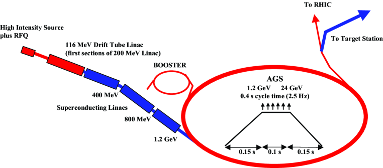
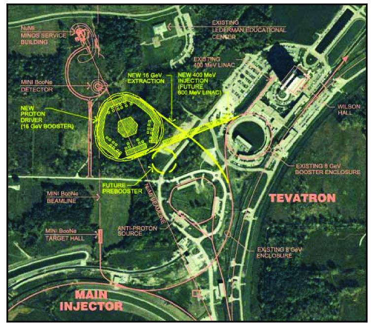
The AGS repetition rate is increased from 0.5 Hz to 2.5 Hz by adding power supplies to permit ramping the ring more quickly. No new technology is required for this—the existing supplies are replicated and the magnets are split into six sectors rather than the two used presently. The total proton charge (1014 ppp in six bunches) is only 40% higher than the current performance of the AGS. However, due to the required short bunches, there is a large increase in peak current and concomitant need for an improved vacuum chamber; this is included in the upgrade. The six bunches are extracted separately, spaced by 20 ms, so that the target, induction linacs, and rf systems that follow need only deal with single bunches at an instantaneous repetition rate of 50 Hz (average rate of 15 Hz). The average proton beam power is 1 MW. A possible future upgrade to 2 1014 ppp and 5 Hz could give an average beam power of 4 MW. At this higher intensity, a superconducting bunch compressor ring would be needed to maintain the rms bunch length at 3 ns.
If the facility were built at Fermilab, the proton driver would be a newly constructed 16 GeV rapid cycling booster synchrotron FNALbooster . The planned facility layout is shown in Fig. 13. The initial beam power would be 1.2 MW, and a future upgrade to 4 MW would be possible. The Fermilab design parameters are included in Table 6. A less ambitious and more cost-effective 8 GeV proton driver option has also been considered for Fermilab FNALbooster ; this too might be the basis for a proton driver design.
| BNL | FNAL | |
| Total beam power (MW) | 1 | 1.2 |
| Beam energy (GeV) | 24 | 16 |
| Average beam current (A) | 42 | 72 |
| Cycle time (ms) | 400 | 67 |
| Number of protons per fill | ||
| Average circulating current (A) | 6 | 2 |
| No. of bunches per fill | 6 | 18 |
| No. of protons per bunch | ||
| Time between extracted bunches (ms) | 20 | 0.13 |
| Bunch length at extraction, rms (ns) | 3 | 1 |
III.2 Target and Capture
A mercury jet target is chosen to give a high yield of pions per MW of incident proton power. The 1 cm diameter jet is continuous, and is tilted with respect to the beam axis. The target layout is shown in Fig. 14.
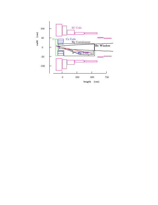
We assume that the thermal shock from the interacting proton bunch fully disperses the mercury, so the jet must have a velocity of 20–30 m/s to be replaced before the next bunch. Calculations of pion yields that reflect the detailed magnetic geometry of the target area have been performed with the MARS code MARSstudyii . To avoid mechanical fatigue problems, a mercury pool serves as the beam dump. This pool is part of the overall target—its mercury is circulated through the mercury jet nozzle after passing through a heat exchanger.
Pions emerging from the target are captured and focused down the decay channel by a solenoidal field that is 20 T at the target center, and tapers down, over 18 m, to a periodic (0.5 m) superconducting solenoid channel () that continues through the phase rotation to the start of bunching. Note that the longitudinal direction of the fields in this channel do not change sign from cell to cell as they do in the cooling channel. The 20 T solenoid, with a resistive magnet insert and superconducting outer coil, is similar in character to the higher field (up to 45 T), but smaller bore, magnets existing at several laboratories ITERmag . The magnet insert is made with hollow copper conductor having ceramic insulation to withstand radiation. MARS MARSstudyii simulations of radiation levels show that, with the shielding provided, both the copper and superconducting magnets could have a lifetime greater than 15 years at 1 MW.
In Study I, the target was a solid carbon rod. At high beam energies, this implementation has a lower pion yield than the mercury jet, and is expected to be more limited in its ability to handle the proton beam power, but should simplify the target handling issues that must be dealt with. At lower beam energies, say 6 GeV, the yield difference between C and Hg essentially disappears, so a carbon target would be a competitive option with a lower energy driver. Present indications Ref:ORNLtgt are that a carbon-carbon composite target can be tailored to tolerate even a 4 MW proton beam power—a very encouraging result. Other alternative approaches, including a rotating Inconel band target, and a granular Ta target are also under consideration, as discussed in Study II EPP:studyii . Clearly there are several target options that could be used for the initial facility.
III.3 Phase Rotation
The function of the phase rotation section in a neutrino factory is to reduce the energy spread of the collected muon beam to a manageable level, allowing reasonable throughput in the subsequent system components. The following description refers specifically to the properties of the U.S. Feasibility Study 2 for a neutrino factory. The initial pions are produced in the mercury target with a very wide range of momenta. The momentum spectrum peaks around 250 MeV/, but there is a tail of high energy pions that extends well beyond 1 GeV. The pions are spread in time over about 3 ns, given by the pulse duration of the proton driver. After the 18 m long tapered collection solenoid and an 18 m long drift section, where the beam is focused by 1.25 T solenoids, most of the low energy pions have decayed into muons. At this point the muon energy spectrum also extends over an approximately 1 GeV range and the time spectrum extends over approximately 50 ns. However, there is a strong correlation between the muon energy and time that can be used for “phase rotation”.
| Induction Linac | 1 | 2 | 3 | |
|---|---|---|---|---|
| Length | m | 100 | 80 | 100 |
| Peak gradient | MV/m | 1.5 | -1.5 | 1.0 |
| Pulse FWHM | ns | 250 | 100 | 380 |
| Pulse start offset | ns | 55 | 0 | 55 |
In the phase rotation process an electric field is applied at appropriate times to decelerate the leading high energy muons and to accelerate the trailing low energy ones. Since the bunch train required by a neutrino factory can be very long, it is possible to minimize the energy spread using induction linacs. The induction linac consists of a simple non-resonant structure, where the drive voltage is applied to an axially symmetric gap that encloses a toroidal ferromagnetic material. The change in flux in the magnetic core induces an axial electric field that provides particle acceleration. The induction linac is typically a low gradient structure that can provide acceleration fields of varying shapes and time durations from tens of nanoseconds to several microseconds. Some properties of the induction linacs are given in Table 7.
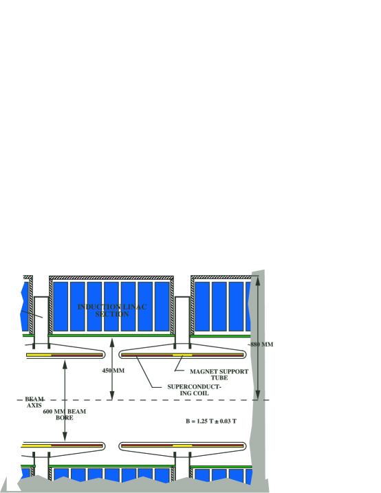
Three induction linacs are used in a system that reduces distortion in the phase-rotated bunch, and permits all induction units to operate with unipolar pulses. The induction units are similar to those being built for the DARHT project daarht . The 1.25 T beam transport solenoids are placed inside the induction cores in order to avoid saturating the core material, as shown in Fig. 15.
Between the first and second induction linacs two liquid hydrogen absorbers (each 1.7 m long and 30 cm radius) are used to (1) provide some initial cooling of the transverse emittance of the muon beam and (2) lower the average momentum of the beam to match better the downstream cooling channel acceptance. This process is referred to as “mini-cooling”. The direction of the solenoid magnetic field is reversed between the two absorbers. The presence of material in the beam path destroys the conservation of canonical angular momentum that occurs when a particle enters and leaves a solenoid in vacuum. The build-up of this angular momentum would eventually lead to emittance growth. However, this growth can be minimized by periodically reversing the direction of the field.
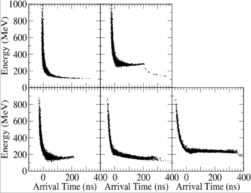
The beam at the end of the phase rotation section has an average momentum of about 250 MeV/c and an rms fractional energy spread of 4.4%. Figure 16 shows the evolution of the beam distribution in the phase rotation section.
III.4 Buncher
The long beam pulse (400 ns) after the phase rotation is then bunched at 201.25 MHz prior to cooling and acceleration at that frequency. The bunching is done in a lattice identical to that at the start of the cooling channel, and is preceded by a matching section from the 1.25 T solenoids into this lattice. The bunching has three stages, each consisting of rf (with increasing acceleration) followed by drifts (with decreasing length). In the first two rf sections, second-harmonic 402.5 MHz rf is used together with the 201.25 MHz primary frequency to improve the capture efficiency. The 402.5 MHz cavities are designed to fit into the bore of the focusing solenoids, in the location corresponding to that of the liquid hydrogen absorber in the downstream cooling channel. Their aperture radius for the 402.5 MHz cavities is 20 cm at the IRIS, while that of the 201.25 MHz cavities is 25 cm. The gradients on axis in the cavities are 6.4 MV/m for the 402.5 MHz cavities, and range from 6 to 8 MV/m for the 201.25 MHz cavities. The resulting bunches fill the 201.25 MHz stationary rf bucket. Figure 17 shows the evolution of the longitudinal distribution in the buncher.
III.5 Cooling
The transverse emittance of the muon beam after phase rotation and bunching must be reduced in order to fit into the downstream accelerators and storage ring. Ionization cooling is currently the only feasible option for cooling the beam within the muon lifetime. In ionization cooling the transverse and longitudinal momenta are lowered in the absorbers, but only the longitudinal momentum is restored by the rf. The following description refers specifically to the properties of the U.S. Feasibility Study 2 for a neutrino factory. Transverse emittance cooling is achieved using cooling cells that (1) lower the beam energy by 7-12 MeV in liquid hydrogen absorbers, (2) use 201 MHz rf cavities to restore the lost energy, and (3) use 3–5 T solenoids to strongly focus the beam at the absorbers. At the end of the cooling channel the rms normalized transverse emittance is reduced to about 2.5 mm rad.
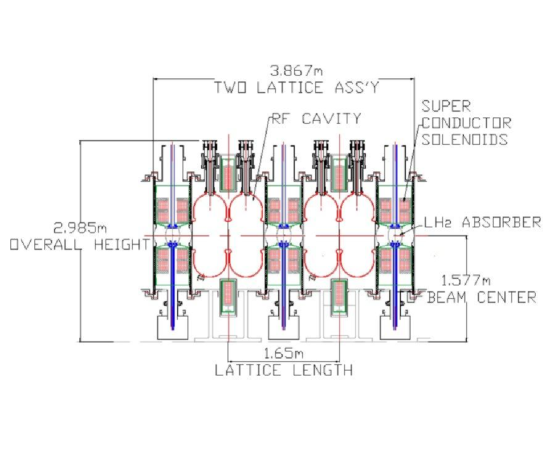
Each cell of the lattice contains three solenoids. The direction of the solenoidal field reverses in alternate cells in order to prevent the build-up of canonical angular momentum, as mentioned above in the discussion of mini-cooling. In analogy with the FODO lattice this focusing arrangement is referred to as a (S)FOFO lattice. Multiple Coulomb scattering together with the focusing strength determine the asymptotic limit on the transverse emittance that the cooling channel can reach. The focusing strength in the channel is tapered so that the angular spread of the beam at the absorber locations remains large compared to the characteristic spread from scattering. This is achieved by keeping the focusing strength inversely proportional to the emittance, i.e., increasing it as the emittance is reduced. The solenoidal field profile was chosen to maximize the momentum acceptance (22%) through the channel. To maintain the tapering of the focusing it was eventually necessary to reduce the cell length from 2.75 m in the initial portion of the channel to 1.65 m in the final portion. A layout of the shorter cooling cells is shown in Fig. 18.
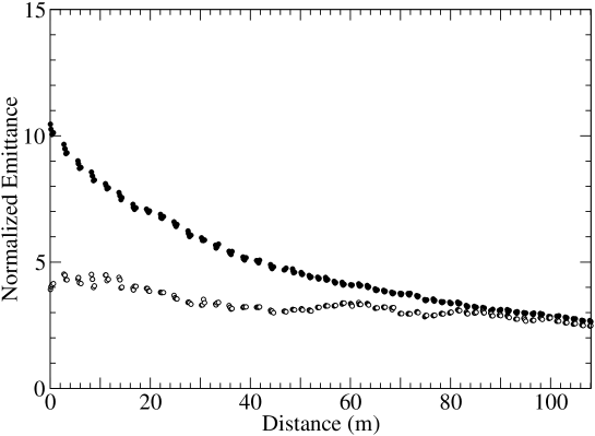
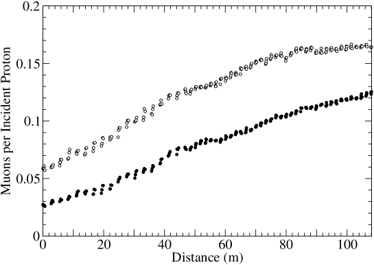
Figure 19 shows a simulation of cooling in this channel. The transverse emittance decreases steadily along the length of the channel. This type of channel only cools transversely, so the longitudinal emittance increases until the rf bucket is full and then remains fairly constant as particles are lost from the bucket. A useful figure of merit for cooling at a neutrino factory is the increase in the number of muons that fit within the acceptance of the downstream accelerators. This is shown in Fig. 20. At each axial position the number of muons is shown that fall within two acceptances appropriate to a downstream accelerator. Both acceptances require the muon longitudinal phase space be less than 150 mm. The density of particles within a normalized transverse acceptance, for example, steadily increases by a factor of about 3 over the channel length, clearly showing the results of cooling. The saturation of the yield determined the chosen channel length of 108 m.
III.6 Acceleration
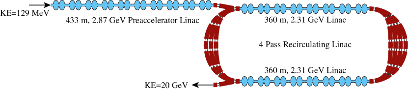
The layout of the acceleration system is shown in Fig. 21, and its parameters are listed in Table 8. The acceleration system consists of a preaccelerator linac followed by a four-pass recirculating linac. The recirculating linac allows a reduction in the amount of rf required for acceleration by passing the beam through linacs multiple times. The linacs are connected by arcs, and a separate are is used for each pass. At low energies, however, the large emittance of the beam would require a much shorter cell length and larger aperture than is desirable and needed at higher energies. This, combined with difficulties in injecting the large emittance and energy spread beam into the recirculating accelerator, and the loss of efficiency due to the phase slip at low energies, lead to the necessity for a linac that precedes the recirculating linac.
A 20 m SFOFO matching section, using normal conducting rf systems, matches the beam optics to the requirements of a 2.87 GeV superconducting rf linac with solenoidal focusing. The linac is in three parts. The first part has a single 2-cell rf cavity unit per period. The second part, as a longer period becomes possible, has two 2-cell cavity units per period. The last section, with still longer period, accommodates four 2-cell rf cavity units per period. See Tables 9 and 10 for details of the rf cryostructures and cavities. Figure 22 shows the three cryomodule types that make up the linac.
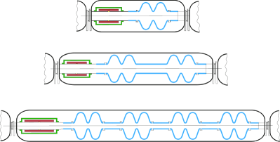
| Injection momentum (MeV/c)/Kinetic energy (MeV) | 210/129.4 |
| Final energy (GeV) | 20 |
| Initial normalized transverse acceptance (mm rad) | 15 |
| rms normalized transverse emittance (mm rad) | 2.4 |
| Initial longitudinal acceptance, (mm) | 170 |
| momentum spread, | |
| bunch length, (mm) | |
| rms energy spread | 0.084 |
| rms bunch length (mm) | 163 |
| Number of bunches per pulse | 67 |
| Number of particles per bunch/per pulse | / |
| Bunch frequency/accelerating frequency (MHz) | 201.25/ 201.25 |
| Average beam power (kW) | 150 |
| Cavities per period | 1 | 2 | 4 |
| Period length (m) | 5 | 8 | 13 |
| Number of periods | 11 | 16 | 19 |
| Cavity type | A | A | B |
| Solenoid full aperture (cm) | 46 | 46 | 36 |
| Solenoid length (m) | 1 | 1 | 1.5 |
| Maximum solenoid field (T) | 2.1 | 2.1 | 4.2 |
| A | B | |
| Frequency (MHz) | 201.25 | 201.25 |
| Cells per cavity | 2 | 2 |
| Aperture diameter (cm) | 46 | 30 |
| Energy gain (MV) | 22.5 | 25.5 |
| rf pulse length (ms) | 3 | 3 |
| Input Power (kW) | 980 | 1016 |
| Peak surface field (MV/m) | 23.1 | 24.3 |
This linac is followed by a single four-pass recirculating linear accelerator (RLA) that raises the energy from 2.5 GeV to 20 GeV. The RLA uses the same layout of four 2-cell superconducting rf cavity structures as the long cryomodules in the linac, but utilizes quadrupole triplet focusing, as indicated in Fig. 23.
The arcs have an average radius of 62 m, and are all in the same horizontal plane. They also utilize triplet focusing. There are around 120 arc cells, with 2.15 m dipoles, and triplet quadrupoles which are very similar to those in the linacs. The required full quadrupole apertures vary from 20 cm to 12 cm, and the dipole gaps vary from 14 cm to 9 cm. All magnet pole tip fields are under 2 T, except in the switchyard where they are as high as 2.3 T in some cases (and the magnet apertures rise to 21 cm).
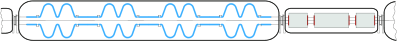
The 4.5 K-equivalent cryogenic load for the entire acceleration system is 27.9 kW. In Study I, where the final beam energy was chosen to be 50 GeV, a second RLA is needed. This second RLA is similar to the RLA just described, but considerably larger.
III.7 Storage Ring
After acceleration in the RLA, the muons are injected into the upward-going straight section of a racetrack-shaped storage ring with a circumference of 358 m. Parameters of the ring are summarized in Table 11. High-field superconducting arc magnets are used to minimize the arc length. Minimizing the arc length for a given length of straight maximizes the fraction of the circumference contained in the straight section, thereby maximizing the fraction of neutrinos (around 35% in our case) decaying toward the detector.
Furthermore, the beta functions in the downward-going straight (which is pointed toward the detector) are made large to reduce the angular divergence of the beam. This ensures that the angular divergence of the beam is dominated by the calculable relativistic angular divergence of the decay neutrinos. The goal of this is not only to make the angular divergence of the neutrino beam as small as possible and therefore maximize the flux, but it also reduces the experimental uncertainty associated with an uncertainty in the flux that would come from an uncertainty in the angular divergence of the muon beam.
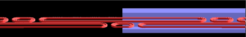
All muons are allowed to decay; the maximum heat load from their decay electrons is 42 kW (126 W/m). This load is too high to be dissipated in the superconducting coils. For Study II, a magnet design (see Fig. 24) has been chosen that allows the majority of these electrons to exit between separate upper and lower cryostats, and be dissipated in a dump at room temperature. To maintain the vertical cryostat separation in focusing elements, skew quadrupoles are employed in place of standard quadrupoles. The result is a skew FODO lattice, giving diagonal oscillations, as opposed to the horizontal and vertical oscillations of the usual upright FODO lattice. In order to maximize the average bending field, Nb3Sn pancake coils are employed. One coil of the bending magnet is extended and used as one half of the previous (or following) skew quadrupole to minimize unused space. Figure 26 shows a layout of the ring as it would be located at BNL. (The existing 110 m high BNL smokestack is shown for scale.) For site-specific reasons, the ring is kept above the local water table and is placed on a roughly 30 m high berm. This requirement places a premium on a compact storage ring.
The beam is allowed to debunch in the storage ring. In one muon lifetime (0.42 ms), a bunch with the full energy spread () will have its total length increase by 0.51 s (the storage ring is 1.19 s long, and the bunch train starts out 0.33 s long). If one wishes to avoid the increase in the bunch train length, one could install rf cavities, but the voltage required to avoid energy spread increase for the momentum compaction in this ring is prohibitive: a better solution would be a ring re-designed to have very low momentum compaction.
| Energy (GeV) | 20 |
| Circumference (m) | 358.18 |
| Normalized transverse acceptance (mm rad) | 30 |
| Energy acceptance (%) | 2.2 |
| Momentum compaction | 0.028 |
| Arc | |
| Length (m) | 53.09 |
| No. cells per arc | 10 |
| Cell length (m) | 5.3 |
| Phase advance () | 60 |
| Dipole length (m) | 1.89 |
| Dipole field (T) | 6.93 |
| Skew quadrupole length (m) | 0.76 |
| Skew quadrupole gradient (T/m) | 35 |
| (m) | 8.6 |
| Production Straight | |
| Length (m) | 126 |
| (m) | 200 |
For Study I, a conventional superconducting ring was utilized to store the 50 GeV muon beam. The heat load from muon decay products in this scenario is managed by having a liner inside the magnet bore to absorb the decay products. This approach is likewise available for BNL, provided some care is taken to keep the ring compact; acceptable lattice solutions have been found for this option as well.
III.8 Overall Machine Summary
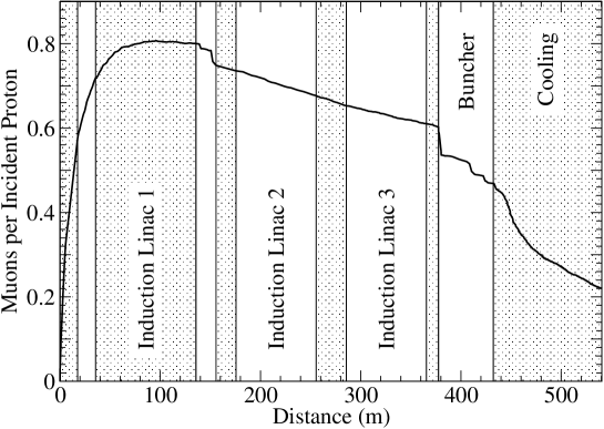
| Section | /p | Loss |
|---|---|---|
| Phase rotation | 0.60 | — |
| Buncher | 0.47 | 22% |
| Cooling | 0.22 | 53% |
| Accelerator aperture | 0.16 | 26% |
| Preaccelerator Linac | 0.15 | 10% |
| Recirculating Linac | 0.13 | 10% |
Figure 25 shows the muons per incident proton in the “front end” (everything before the acceleration) of the Study II neutrino factory. Table 12 gives the values at the ends of several sections and the losses in those sections. These significant losses are a necessary cost of making a low-emittance beam that can be accelerated and injected into a storage ring.
An overall layout of the Neutrino Factory on the BNL site is shown in Fig. 27. Figure 28 shows the equivalent picture for a facility on the Fermilab site. In this latter case, the layout includes the additional RLA and longer storage ring needed to reach 50 GeV. Clearly the footprint of a Neutrino Factory is reasonably small, and such a machine would fit easily on the site of either BNL or Fermilab.
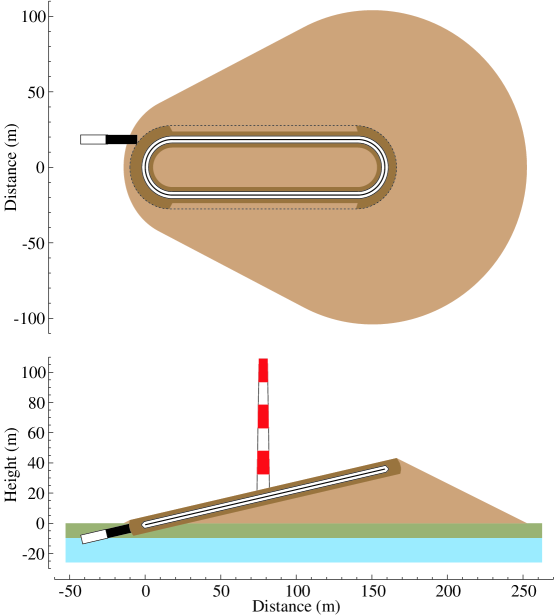
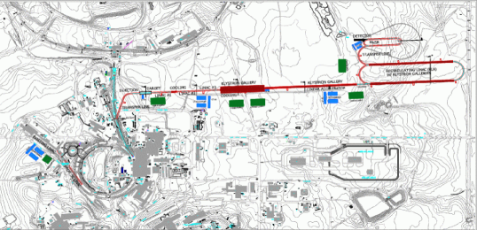
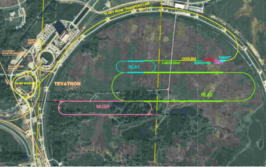
III.9 Detector
The Neutrino Factory, plus its long-baseline detector, will have a physics program that is a logical continuation of current and near-future neutrino oscillation experiments in the U.S., Japan, and Europe. Moreover, detector facilities located in experimental areas near the neutrino source will have access to integrated neutrino intensities – times larger than previously available ( neutrinos per year compared with –).
The detector site taken for Study II is the Waste Isolation Pilot Plant (WIPP) in Carlsbad, New Mexico. The WIPP site is approximately 2900 km from BNL. Space is potentially available for a large underground physics facility at depths of 740–1100 m, and discussions are under way between DOE and the UNO project DET:uno on the possible development of such a facility.
III.9.1 Far Detector
Specifications for the long-baseline Neutrino Factory detector are rather typical for an accelerator-based neutrino experiment. However, the need to maintain a high neutrino rate at these long distances requires detectors 3–10 times more massive than those in current neutrino experiments. Clearly, the rate of detected neutrinos depends on two factors—the source intensity and the detector size. In the final design of a Neutrino Factory, these two factors would be optimized together.
Two options are considered for the WIPP site: a 50 kton steel–scintillator–proportional-drift-tube (PDT) detector or a water-Cherenkov detector. The PDT detector would resemble MINOS. Figure 29 shows a 50 kton detector with dimensions m. A detector of this size would record up to events per year.
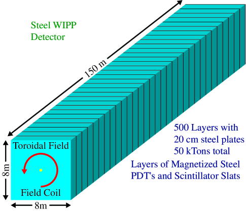
A large water-Cherenkov detector would be similar to SuperKamiokande, but with either a magnetized water volume or toroids separating smaller water tanks. The detector could be the UNO detector DET:uno , currently proposed to study both proton decay and cosmic neutrinos. UNO would be a 650 kton water-Cherenkov detector segmented into a minimum of three tanks (see Fig. 30). It would have an active fiducial mass of 440 kton and would record up to events per year from the Neutrino Factory beam.
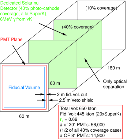
Another possibility for a Neutrino Factory detector is a massive liquid-argon magnetized detector landd that would also attempt to detect proton decay, as well as solar and supernova neutrinos.
III.9.2 Near Detector
As noted, detector facilities located on-site at the Neutrino Factory would have access to unprecedented intensities of pure neutrino beams. This would enable standard neutrino physics studies, such as , structure functions, neutrino cross sections, nuclear shadowing and pQCD to be performed with much higher precision than previously obtainable. In addition to its primary physics program, the near detector can also provide a precise flux calibration for the far detector, though this may not be critical given the ability to monitor the storage ring beam intensity independently.
A compact liquid-argon time projection chamber (TPC; similar to the ICARUS detector ICARUS ), cylindrically shaped with a radius of 0.5 m and a length of 1 m, would have an active mass of kg and a neutrino event rate O(10 Hz). The TPC could be combined with a downstream magnetic spectrometer for muon and hadron momentum measurements. At these neutrino intensities, it is even possible to have an experiment with a relatively thin Pb target (1 ), followed by a standard fixed-target spectrometer containing tracking chambers, time-of-flight, and calorimetry, with an event rate (1 Hz).
III.10 Staging Options
It seems quite possible—perhaps even likely—that the Neutrino Factory would be built in stages, both for programmatic and for cost reasons. Here we outline a possible staging concept that provides good physics opportunities at each stage. The staging scenario we consider is not unique, nor is it necessarily optimized. Depending on the results of our technical studies and the results of continued searches for the Higgs boson, it is hoped that the Neutrino Factory is really the penultimate stage, to be followed later by a Muon Collider (Higgs Factory). We assume this possibility in the staging discussion that follows. Because the physics program would be different at different stages, it is impractical at this time to consider detector details.
III.10.1 Stage 1
In the first stage, we envision a Proton Driver and a Target Facility to create superbeams. The Driver could begin with a 1 MW beam level (Stage 1) or could be designed from the outset to reach 4 MW (Stage 1a). (Since the cost differential between 1 and 4 MW is not expected to be large, we do not consider any intermediate options here.) It is assumed, as was the case for both Study I and Study II, that the Target Facility is built from the outset to accommodate a 4 MW beam. Based on the Study II results, a 1 MW beam would provide about /s ( /year) and a 4 MW beam about /s ( /year) into a solenoid channel.
In addition to the neutrino program, this stage will also benefit , , and programs, as discussed in proton-physics ; low-pbar .
III.10.2 Stage 2
In Stage 2, we envision a muon beam that has been phase rotated (to give a reasonably low momentum spread) and transversely cooled. In the nomenclature of Study II, this stage takes us to the end of the cooling channel. Thus, we have access to a muon beam with a central momentum of about 200 MeV/c, a transverse (normalized) emittance of 2.7 mm rad and an rms energy spread of about 4.5%. The intensity of the beam would be about /s ( /year) at 1 MW, or /s ( /year) at 4 MW. If more intensity were needed, and if less cooling could be tolerated, the length of the cooling channel could be reduced. As an example, stopping at the end of Lattice 1 instead of the end of Lattice 2 in the Study II cooling channel would result in an increase of transverse emittance by roughly a factor of two. This is an appropriate stage to mount an experiment to search for a non-zero muon electric dipole moment.
III.10.3 Stage 3
In Stage 3, we envision using the Pre-acceleration Linac to raise the beam energy to roughly 2.5 GeV. At this juncture, it may be appropriate to consider a small storage ring, comparable to the ring at BNL, to be used for the next round of muon experiments.
III.10.4 Stage 4
At Stage 4, we envision having a complete Neutrino Factory operating with a 20 GeV storage ring. This stage includes the RLA and the storage ring. If it were necessary to provide a 50 GeV muon beam as Stage 4a, an additional RLA and a larger storage ring would be needed.
III.10.5 Stage 5
In Stage 5, we could envision an entry-level Muon Collider operating as a Higgs Factory. Because the initial muon beam must be prepared as a single bunch of each charge, an additional ring for the proton driver to coalesce proton bunches into a single pulse is anticipated. The cooling will have to be significantly augmented. First, a much lower transverse emittance is needed, and second, it will be necessary to provide longitudinal cooling (emittance exchange) to maintain a reasonable transmission of the muons. The additional cooling will permit going to smaller solenoids and higher frequency rf systems (402.5 or perhaps 805 MHz), which should provide more cost-effective cooling. Next, we will need considerably more acceleration, though with smaller energy acceptance and aperture requirements than at present. Lastly, we will need a very low lattice for the collider ring, along with mitigation of the potentially copious background levels near the interaction point. In this case the detector is, in effect, part of the collider ring, and its design must be an integral part of the overall ring design.
IV Muon Colliders
The primary advantage of using muons in a lepton collider arises from the fact that the muon is 200 times heavier than the electron. It is thus possible to accelerate muons using circular accelerators that are compact and fit on existing accelerator sites. See Figure 31 for a comparison of relative sizes of muon colliders ranging from 500 GeV to 3 TeV center of mass energies with respect to the LHC, SSC, and NLC. Once the problem of cooling a muon beam to sufficiently small emittances is solved and the beams can be accelerated, higher energies are much more easily obtained in a muon collider than in the linear electron-positron collider. Because the muon is unstable, it is necessary to cool and accelerate the beam before a substantial number have decayed. The number of turns in a muon lifetime is independent of the muon momentum for a given magnetic field, since both the circumference and the muon lifetime in the laboratory frame scale with muon momentum. With typical bending magnetic fields( 5 Tesla) available with today’s technology, the muons last 1000 turns before half of them have decayed in the collider ring.
Muon decay also gives rise to large numbers of electrons that can affect the cryogenics of the magnets in the machine as well as pose serious background problems for detectors in the collision region. The 1999 Status Report INTRO:ref5 contains an excellent summary of the problems (and possible solutions) one faces on the way to a muon collider.
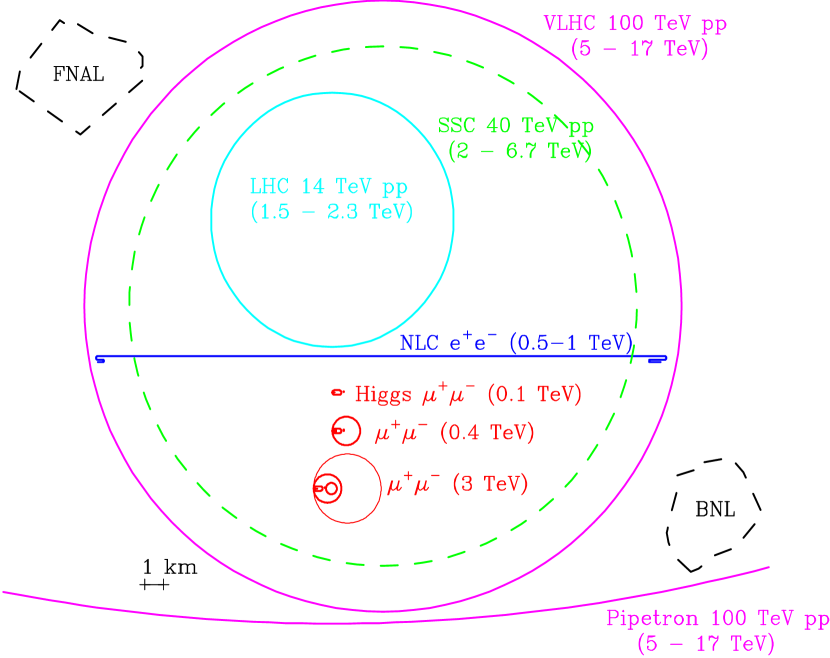
Figure 32 shows a schematic of such a muon collider, along with a depiction of the possible physics that can be addressed with each stage of the facility. Some of the ideas needed to obtain longitudinal cooling necessary for the Muon Collider are discussed in section IV.2 and some of the parameters of the accelerator system for higher energy colliders are discussed in section IV.3 below.
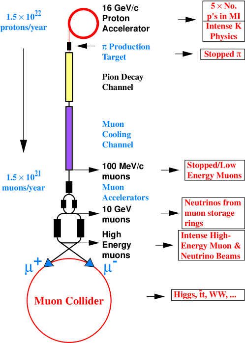
IV.1 Higgs Factory Requirements
The emittance of the muon beam needs to be reduced by a factor of 106 from production INTRO:ref5 to the point of collision for there to be significant luminosity for experiments. Table 13 lists the transverse and longitudinal emittances at the end of the decay channel, Study-II EPP:studyii cooling channel and those needed for a 0.1 TeV Center of Mass Energy Muon Collider, also known as a Higgs Factory. It can be seen that one needs to cool by a factor of 20 in the transverse dimension and 3 in the longitudinal dimension from the Study-II emittances to achieve the emittances necessary for a Higgs factory.
| Emittance at end of | Transverse emittance ( mm) | Longitudinal emittance ( mm) |
|---|---|---|
| Decay Channel | 17 | 150 |
| Study-II cooler | 2.6 | 30 |
| Higgs Factory cooler | 0.14 | 9 |
This can be achieved by ionization cooling similar to the scheme described in the section III. The transverse emittance is reduced during ionization cooling, since only the longitudinal energy loss is replaced by rf acceleration. However, due to straggling, the longitudinal energy spread of the beam increases, even if the average longitudinal energy of the beam is kept constant. The longitudinal emittance thus grows in a linear cooling channel. In order to cool longitudinally, one needs to create dispersion in the system and have wedge absorbers at the point of maximum dispersion so that the faster particles go through the thicker parts of the wedge. This results in a reduction in longitudinal emittance accompanied by an increase in transverse emittance and is thus called emittance exchange.
The status report INTRO:ref5 outlines the details of the acceleration and collider ring for the 0.1 TeV Higgs factory, shown schematically in Fig. 33. Table 14 gives a summary of the parameters of various muon colliders including three different modes of running the Higgs Collider that have varying beam momentum spreads. Additional information about the Muon Collider can be found in gail ; higgsreport .
| CoM energy (TeV) | 3 | 0.4 | 0.1 | ||
| energy (GeV) | 16 | 16 | 16 | ||
| ’s/bunch | |||||
| Bunches/fill | 4 | 4 | 2 | ||
| Rep. rate (Hz) | 15 | 15 | 15 | ||
| power (MW) | 4 | 4 | 4 | ||
| /bunch | |||||
| power (MW) | 28 | 4 | 1 | ||
| Wall power (MW) | 204 | 120 | 81 | ||
| Collider circum. (m) | 6000 | 1000 | 350 | ||
| Ave bending field (T) | 5.2 | 4.7 | 3 | ||
| Rms % | 0.16 | 0.14 | 0.12 | 0.01 | 0.003 |
| 6-D | |||||
| Rms ( mm-mrad) | 50 | 50 | 85 | 195 | 290 |
| (cm) | 0.3 | 2.6 | 4.1 | 9.4 | 14.1 |
| (cm) | 0.3 | 2.6 | 4.1 | 9.4 | 14.1 |
| spot m) | 3.2 | 26 | 86 | 196 | 294 |
| IP (mrad) | 1.1 | 1.0 | 2.1 | 2.1 | 2.1 |
| Tune shift | 0.044 | 0.044 | 0.051 | 0.022 | 0.015 |
| (effective) | 785 | 700 | 450 | 450 | 450 |
| Luminosity cm-2s-1 | |||||
| Higgs/year | |||||
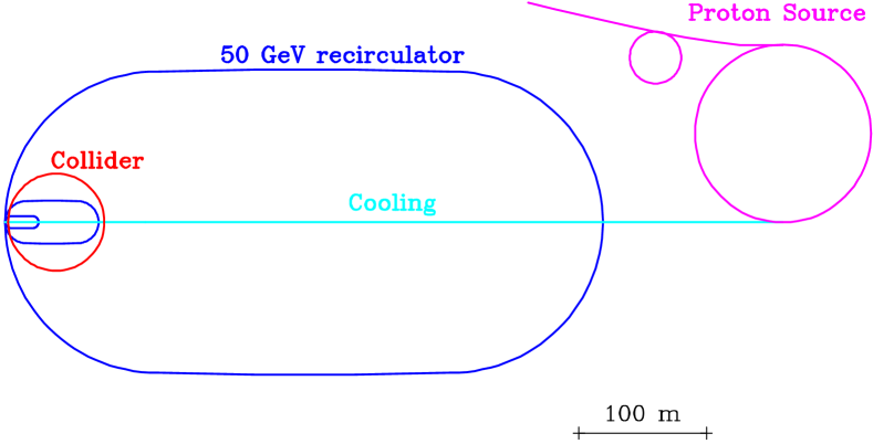
IV.2 Longitudinal Cooling
At the time of writing of the status report INTRO:ref5 there was no satisfactory solution for the emittance exchange problem and this remained a major stumbling block towards realizing a muon collider. However, ring coolers have been found to hold significant promise in cooling in 6-dimensional phase space. Another advantage of ring coolers is that one can circulate the muons many turns, thereby reusing the cooling channel elements. Several meetings on emittance exchange were held eemeets and a successful workshop eework was held in 2001, where we explored in some depth several kinds of ring coolers. These options differ primarily in the type of focusing used to contain the beam. We describe the current status of our understanding of three types of ring coolers here.
IV.2.1 Solenoidal Ring Coolers
The basic design of the solenoidal ring cooler balb1 is presented in Figure 34. Eight focusing dipole magnets with an index are used for bending and focusing of the beam. Each of these dipoles bends the beam through 45 degrees with a central orbit bending radius of 52 cm. We have done calculations to show that such dipoles are buildable. Figure 36 shows a configuration of such a dipole and the resulting magnetic field components calculated using a 3D field calculation program. There are 4 long solenoids containing rf cavities and liquid hydrogen absorbers for transverse cooling. A magnetic field of 2.06 T at the end regions of the solenoids provides the same transverse focusing as the bending magnets. The magnetic field adiabatically increases to 5.15 T towards the center of the solenoid in order to produce a small function (25-30 cm) at the absorbers. The short solenoids are designed to create an appropriate dispersion function that is zero at the long solenoids, which house the 200 MHz rf cavities. Their field is at the edges and T centrally. A symmetric field flip is required in the short solenoids to prevent the build up of canonical angular momentum. This field flip causes the dispersion in the long solenoids housing the rf cavities to be zero while permitting a non-zero dispersion at the lithium hydride wedge absorbers at the centers of the short solenoids which then produce longitudinal cooling via emittance exchange.
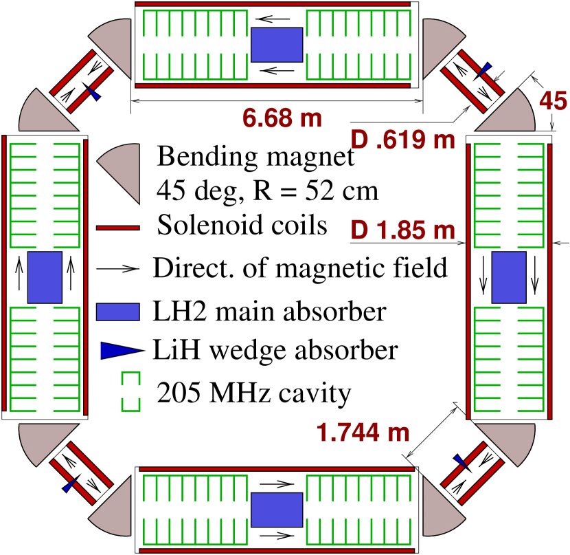
| Circumference | 36.963 m |
| Nominal energy at short | |
| straight section | 250 MeV |
| Bending field | 1.453 T |
| Norm. field gradient | 0.5 |
| Max. solenoid field | 5.155 T |
| rf frequency | 205.69 MHz |
| Accelerating gradient | 15 MeV/m |
| Main absorber length | 128 cm |
| LiH wedge absorber | 14 cm |
| Grad. of energy loss | 0.75 MeV/cm |
| Number of turns | 0 | 10 | 15 |
| emittance (cm) | 1.2 | 0.24 | 0.21 |
| emittance (cm) | 1.2 | 0.24 | 0.21 |
| emittance (cm) | 1.5 | 0.79 | 0.63 |
| 6-D emitttance (cm3) | 2.2 | 0.045 | 0.028 |
| 6-D cooling factor | 1 | 49 | 79 |
| Trans. w/o decay | 1 | 0.72 | 0.71 |
| Trans. with decay | 1 | 0.56 | 0.48 |
| Merit factor | 1 | 27 | 38 |
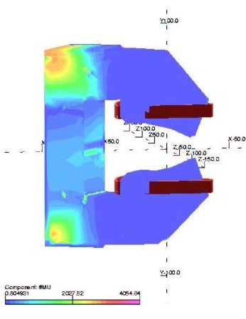
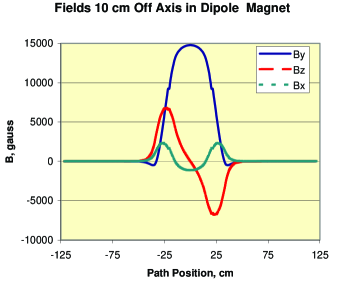
Evolution of the beam emittance and transmission is shown in Figure 35 as a function of the number of turns in the ring. In 15 turns, the transverse emittance decreases from 1.2 cm to 0.21 cm yielding a cooling factor of 5.7, the longitudinal emittance decreases from 1.5 cm to 0.63 cm (cooling factor 2.4), and the 6-D emittance decreases from 2.2 cm3 to 0.028 cm3, with an overall cooling factor 79. The transmission is 0.71 without decay and 0.48 with decay. We define a merit factor for cooling that is the total transmission including decay times the 6-D cooling factor. The merit factor for this ring is then 38. This implies that transverse emittance at the ring cooler is about the same as at a linear SFOFO cooling channel employed in Study-II EPP:studyii , whereas the longitudinal emittance is noticeably less.
This cooler provides mainly transverse cooling and can be used as a part of Neutrino Factory or a muon collider. A cooler specially designed for strong longitudinal cooling (“bunch compressor”) can also be created using a similar scheme. Such a compressor would be a part of a muon collider to shorten muon bunches from 6-8 m (minimal length after decay and phase rotation, see Ref. INTRO:ref5 ) to 0.6-0.8 m acceptable for further cooling by a 200 MHz channel.
Two options for the bunch compressor are considered in Ref. balb4 . The first one is a two-step cooler where each step is very similar to the ring cooler shown in Figure 34. The main difference is that the primary goal in the first cooler is the longitudinal bunching of the beam. This leads to a uniform magnetic field in the long solenoids and lower frequency/voltage of the accelerating rf system (15.6 MHz/4 MeV/m at the first stage vs. 62.5 MHz/8 MeV/m at the second one). Another option is a 15 MHz octagonal cooler composed of the same cells as in Figure 34, but with half the bending magnet angle. Decrease of longitudinal emittance from 43 cm to 2.5-3 cm, as required for muon collider, is obtained in both cases.
We are proceeding with a realistic simulation of this system using Geant and ICOOL that employs realistic magnetic fields kahn produced by field calculation programs.
After the two stage cooler, we still need a factor of 30 in transverse cooling, but we are within a factor of 4 in longitudinal cooling relative to the Higgs factory goals. Lithium lens cooling, which with its strong focusing will cool transversely further while degrading longitudinally due to straggling, is a possibility and is being investigated.
IV.2.2 RFOFO ring coolers
The cooling lattice for the Neutrino Factory (see section III) employs a configuration of fields known as an SFOFO lattice (super-FOFO) where the axial magnetic field profile changes polarity in alternate cells of the lattice. For the ring cooler design under consideration here, we employ an RFOFO lattice (regular-FOFO) where the axial field profile changes polarity in the middle of a cell. As a result all cells in an RFOFO lattice are identical.
The ring cooler design employs a single cell for both transverse cooling and emittance exchange. It uses solenoids for focusing, giving large angular and momentum acceptances. The cell includes dispersion, acceleration, and energy loss in a single thick hydrogen wedge. Figure 37 shows the layout of the cooling ring drawn to scale. The RFOFO lattice was chosen because, unlike in the SFOFO case used in Study-II, all cells are strictly identical, and the presence of an integer betatron resonance within the momentum acceptance is eliminated.
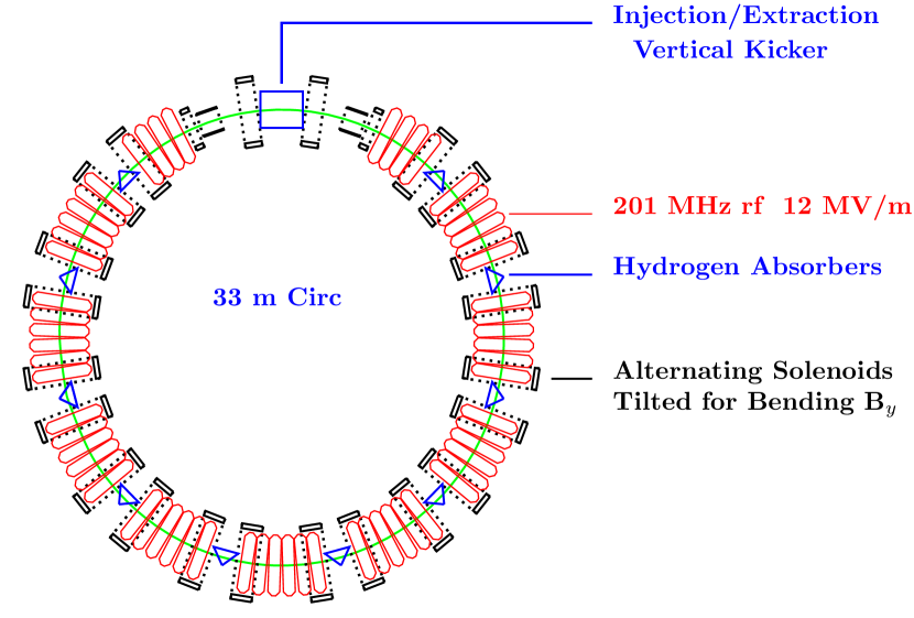
The basic 33 m circumference ring is made up of 12 identical 2.75-m long cells. In the figure, this symmetry is broken for injection and extraction, but the magnetic fields in this insertion are nearly identical to those in the rest of the ring. Figure 38 shows a detailed view of three cells of the lattice, in plan (a) and side (b) views.
a)
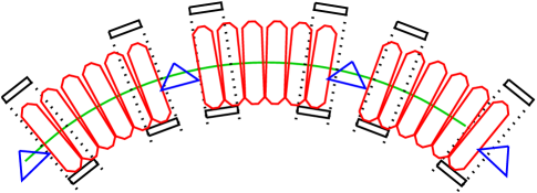
b)
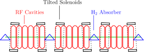
The longitudinal field on-axis has an approximately sinusoidal dependence on position. The beam axis is displaced laterally with respect to the coil centers (as shown in figure 38a) to minimize horizontal fields that cause vertical beam deviations. The lattice transmits particles in the momentum band from 150 to 250 MeV/c. The minimum value of the beta function at the central momentum is 40 cm.
Bending round the ring, and the required dispersion, are provided by applying an approximately 0.125 T vertical bending field generated by alternately tilting the solenoids (as shown in figure 38b). There is no attempt to set the field index (where ) to the 0.5 value; so the focusing is not identical in x and y.
It is found that the acceptance is reduced as the bending field is increased. We thus use a wedge with maximum possible angle (giving zero thickness on one side), and the lowest bending field consistent with adequate emittance exchange. The dispersion at the absorber is approximately 8 cm in a direction 30 degrees from the axis, The dispersion at the center of the rf is of the opposite sign, and also mostly in the direction.
The liquid-hydrogen wedge has a central thickness of 28.6 cm and a total wedge angle of 100 degrees and is rotated 30 degrees from the vertical. The rf cavities are at a frequency of 201.25 MHz and have an accelerating gradient of 12 MV/m.
The ICOOL icool simulation (with results shown in shown Figure 39) used fields calculated from the specified coils, and thus neglects no end field effects. But in this simulation, no absorber, or rf, windows, are included; nor did it include the injection/extraction insertion. The rf was represented by the fields in perfect pillbox cavities. The input tracks were taken from a Study-II EPP:studyii simulation, using distributions from just upstream of the transverse cooling system. The use of Study-II simulated distributions is intended to allow a more realistic estimate of the ring’s performance. No attempt was made to match this beam to the ring dispersion or slight differences in the transverse beta functions.
Figure 39 shows the simulated transmission, transverse emittance, longitudinal emittance, 6-dimensional emittance, and a merit factor vs. length in the ring. is given by:
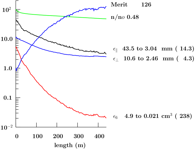
Initially, the emittance falls more rapidly than the , because it is the emittance that is exchanged with the longitudinal. But the Larmor rotations soon mix the and emittances bringing them to a common value.
After a distance of 400 m ( 12 turns), the 6-dimensional emittance has fallen by a factor of 238, with a transmission of 48 % (66% without decay). The merit factor is 136. The same factor for the Study-II cooling lattice, also without windows, is 13. Studies with realistic windows and the injection/extraction insertion added, show lower merit factors, but always far better than the Study-II example.
The design of the injection/ejection channels and kickers will be challenging, and this ring could not be used, as is, to replace the Study-II cooling channel because the bunch train in that case is too long to fit in the ring. Both problems would be removed in a helical cooling channel. The merit factor for such a channel could be even better than that of the ring because it would be possible to “taper” the optics, as a function of distance down the channel, and thus lower the final equilibrium emittance.
IV.2.3 Quadrupole Ring Coolers
Alternative ring designs have been explored which are based on storage rings which consist of conventional quadrupole and dipole magnetic elements instead of solenoids ucla . The strategy has been to utilize the SYNCH storage ring design code synch to develop linear lattice solutions and then transfer the lattice parameters into the ray-tracing tracking code ICOOL icool in which absorbers and energy recovery with rf cavities can be included for full simulation. An example of such a ring is shown in Figure 40 where the elements of a half cell for a 22.5∘ bending cell are depicted schematically. The correspondence between the beam envelope beta and dispersion functions resulting from a simulation with the ICOOL tracking code and the SYNCH calculated values are shown in Figure 41. The full sixteen cell ring is shown in Figure 42.
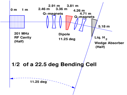
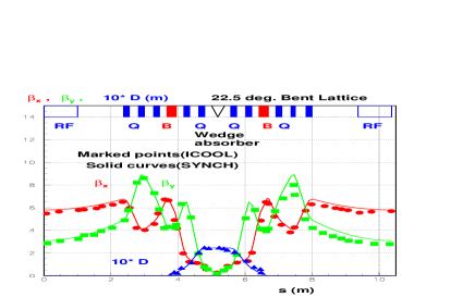
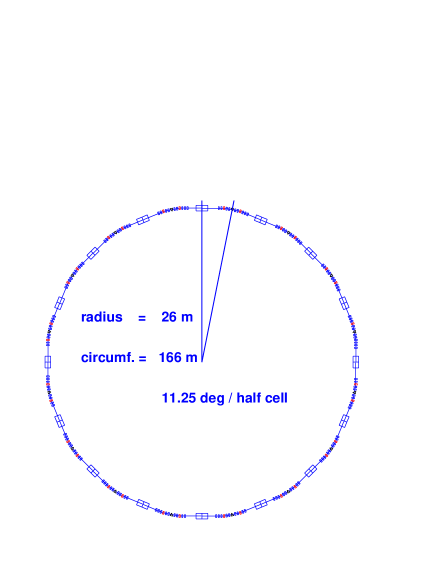
In general, we find that the performance of the rings, as measured in emittance reduction along with particle transmission and decay losses, improves when more compact lattice designs are considered. In Figure 44, the variation of the normalized emittances as a function of ring turns is shown for an eight cell ring. A reduction of normalized emittance is observed for all three dimensions. This particular ring has a total circumference of 30.9 m. Each half cell contains one 22.5∘ combined function dipole proceeded and followed by a single horizontally focusing quadrupole. The average muon beam momentum is 250 MeV/c and liquid hydrogen absorbers with wedge opening angles of 40∘ are used. For each cell, the central beam orbit traverses 24 cm of absorber. The energy loss in the wedge absorbers is compensated with 201 MHz rf cavities with peak on-axis gradients of 16 MV/m.
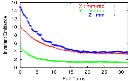
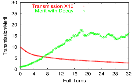
The muon transmission efficiency and total merit factor (muon survival rate times the ratio of initial to final 6-dimensional emittance) is shown in Figure 44 as a function of ring turns. The merit factor reaches 18, while the muon transmission efficiency including decay losses after eighteen full turns is 40%.
Rings in which the focusing function is handled exclusively by the dipole elements have also been explored. In this case, the natural focusing power of the dipole is utilized for horizontal focusing while the entrance and exit dipole edge angles are adjusted to provide the required vertical focusing. Several examples of such lattices have been examined. Because these lattices are more compact than lattices which also include quadrupoles, the performance of these rings tend to be better. As an example, performances with merit factors on the order of 100 have been observed with rings based on four cell lattice with eight 45∘ dipoles. For one case, the entrance and exit angles dipole faces are 7.4∘ and 21.8∘ relative to the normal of the beam trajectory. The ring for this example has a circumference of only 9.8 m and the design of injection/ejection cells may prove to be very challenging.
IV.2.4 Injection into Ring Coolers
The most serious technical problem facing the ring cooler approach is the injection system which may require a very powerful kicker magnet balb5 . The energy stored in the injection kicker goes as the square of the emittance of the beam and inversely as the circumference of the ring. A promising injection scheme that does not use kicker magnets, but instead uses absorbers to degrade the beam energy and rf phase manipulations has been proposed balb6 and is being studied.
IV.3 Higher Energy Muon colliders
Once the required cooling has been achieved to make the first muon collider feasible, acceleration to higher energies becomes possible. Colliders with 4 TeV center of mass energy have been studied INTRO:ref5 and Table 15 lists the parameters for such a collider. The muons are accelerated initially by a linear accelerator followed by a series of recirculating linear accelerators (RLA’s) followed by rapid cycling synchrotrons (RCS’s). The radiation from the neutrinos from the muon decay begins to become a problem at CoM energies of 3 TeV kingnu .
There have been preliminary attempts to study colliders of even higher energy, starting at 10 TeV all the way up to 100 TeV in the center of mass and we include the references to these studies kinghi for the sake of completeness.
| Linac | RLA1 | RLA2 | RCS1 | RCS2 | |
|---|---|---|---|---|---|
| E (GeV) | 0.1 1.5 | 1.5 10 | 10 70 | 70 250 | 250 2000 |
| frf (MHz) | 30 100 | 200 | 400 | 800 | 1300 |
| Nturns | 1 | 9 | 11 | 33 | 45 |
| Vrf(GV/turn) | 1.5 | 1.0 | 6 | 6.5 | 42 |
| Cturn(km) | 0.3 | 0.16 | 1.1 | 2.0 | 11.5 |
| Beam transit time (ms) | 0.0013 | 0.005 | 0.04 | 0.22 | 1.73 |
| (cm) | 50 8 | 4 1.7 | 1.7 0.5 | 0.5 0.25 | 0.25 0.12 |
| (GeV) | 0.005 0.033 | 0.067 0.16 | 0.16 0.58 | 0.58 1.14 | 1.14 2.3 |
| Loss (%) | 5 | 7 | 6 | 7 | 10 |
IV.4 Muon Collider Detectors
Figure 45 shows a strawman muon collider detector for a Higgs factory simulated in Geant. The background from muon decay sources has been extensively studied INTRO:ref5 . At the Higgs factory, the main sources of background are from photons generated by the showering of muon decay electrons. At the higher energy colliders, Bethe-Heitler muons produced in electron showers become a problem. Work was done to optimize the shielding by using specially shaped tungsten cones INTRO:ref5 that reduce the backgrounds resulting from electomagnetic showers from entering the detector. The occupancy levels due to background photons and neutrons in detectors were shown to be similar to those predicted for the LHC experiments. It still needs to be established whether pattern recognition is possible in the presence of these backgrounds, especially the Bethe Heitler muons, which are a unique source of background to muon collider detectors..
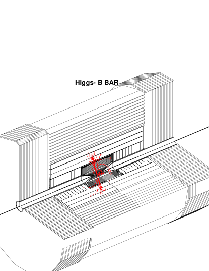
V R&D Status
A successful construction of a muon storage ring to provide a copious source of neutrinos requires several novel approaches to be developed and demonstrated; a high-luminosity Muon Collider requires an even greater extension of the present state of accelerator design. Thus, reaching the full facility performance in either case requires an extensive R&D program.
The required R&D program has been identified for each of the major neutrino factory systems. In particular, some critical components must be prototyped and their performance verified. For example, the cooling channel assumes a normal conducting rf (NCRF) cavity gradient of 17 MV/m at 201.25 MHz, and the acceleration section demands similar performance from superconducting rf (SCRF) cavities at this frequency. In both cases, the requirements are beyond the performance reached to date for cavities in this frequency range. The ability of the target to withstand a proton beam power of up to 4 MW must be confirmed, and, if it remains the technology of choice, the ability of an induction linac unit to coexist with its internal SC solenoid must be verified. Finally, an ionization cooling experiment should be undertaken to validate the implementation and performance of the cooling channel, and to confirm that our simulations of the cooling process are accurate.
Below we give an overview of the MC R&D program goals and list the specific questions we expect address. We also summarize briefly the R&D accomplishments to date
V.1 R&D Program Overview
A Neutrino Factory comprises the following major systems: Proton Driver, Target and (Pion) Capture Section, (Pion-to-Muon) Decay and Phase Rotation Section, Bunching and Matching Section, Cooling Section, Acceleration Section, and Storage Ring. These same categories apply to a Muon Collider, with the exception that the Storage Ring is replaced by a Collider Ring having a low-beta interaction point and a local detector. Parameters and requirements for the various systems are generally more severe in the case of the Muon Collider, so a Neutrino Factory can properly be viewed as a scientifically productive first step toward the eventual goal of a collider.
The R&D program we envision is designed to answer the key questions needed to embark upon a Zeroth-order Design Report (ZDR). The ZDR will examine the complete set of systems needed for a Neutrino Factory, and show how the parts can be integrated into a coherent whole. Although a fully engineered design with a detailed cost estimate is beyond the scope of a ZDR, enough detailed work must been accomplished to ensure that the critical items are technically feasible and that the proposed facility could be successfully constructed and operated at its design specifications. By the end of the full R&D program, it is expected that a formal Conceptual Design Report (CDR) for a Neutrino Factory could be written. The CDR would document a complete and fully engineered design for the facility, including a detailed bottom-up cost estimate for all components. This document would form the basis for a full technical, cost, and schedule review of the construction proposal. Construction could then commence after obtaining approval.
The R&D issues for each of the major systems must be addressed by a mix of theoretical calculation, simulation modeling, and experimental studies, as appropriate. A list of the key physics and technology issues for each major system is given:-
Proton Driver
-
•
Production of intense, short proton bunches, e.g., with space-charge compensation and/or high-gradient, low frequency rf systems
Target and Capture Section
-
•
Optimization of target material (low-Z or high-Z) and form (solid, moving band, liquid-metal jet)
-
•
Design and performance of a high-field solenoid (20 T) in a very high radiation environment
Decay and Phase Rotation Section
-
•
Development of high-gradient induction linac modules having an internal superconducting solenoid channel
-
•
Examination of alternative approaches, e.g., based upon combined rf phase rotation and bunching systems or fixed-field, alternating gradient (FFAG) rings
Bunching and Matching Section
-
•
Design of efficient and cost-effective bunching system
Cooling Section
-
•
Development and testing of high-gradient normal conducting rf (NCRF) cavities at a frequency near 200 MHz
-
•
Development and testing of efficient high-power rf sources at a frequency near 200 MHz
-
•
Development and testing of liquid hydrogen absorbers for muon cooling
-
•
Development and testing of an alternative gaseous-absorber cooling-channel design incorporating pressurized, high-gradient rf cavities.
-
•
Development and testing of candidate diagnostics to measure emittance and optimize cooling channel performance
-
•
Design of beamline and test setup (e.g., detectors) needed for demonstration of transverse emittance cooling
-
•
Development of full six-dimensional analytical theory to guide the design of the cooling section
Acceleration Section
-
•
Optimization of acceleration techniques to increase the energy of a muon beam (with a large momentum spread) from a few GeV to a few tens of GeV (e.g., recirculating linacs, rapid cycling synchrotrons, FFAG rings) for a Neutrino Factory, or even higher energy for a Muon Collider
-
•
Development of high-gradient superconducting rf (SCRF) cavities at frequencies near 200 MHz, along with efficient power sources (about 10 MW peak) to drive them
-
•
Design and testing of components (rf cavities, magnets, diagnostics) that will operate in the muon-decay radiation environment
Storage Ring
-
•
Design of large-aperture, well-shielded superconducting magnets that will operate in the muon-decay radiation environment
Collider
-
•
Cooling of 6D emittance (x, px, y, py, t, E) by up to a factor of
-
•
Design of a collider ring with very low (a few mm) at the interaction point having sufficient dynamic aperture to maintain luminosity for about 500 turns
-
•
Study of muon beam dynamics at large longitudinal space-charge parameter and at high beam-beam tune shift
Detector
-
•
A study of cost trade-offs between increasing the detector mass compared with increasing the beam intensity.
-
•
Simulation studies to define acceptable approaches for a Muon Collider detector operating in a high-background environment
Most of these issues are being actively pursued as part of the ongoing MC R&D program. In a few areas, notably the proton driver and detector, the MC does not currently engage in R&D activities, though independent efforts are under way. Longer-term activities, related primarily to the Muon Collider, are supported and encouraged as resources permit.
V.2 Recent R&D Accomplishments
V.2.1 Targetry
A primary effort of the Targetry experiment E951 at BNL has been to carry out initial beam tests of both a solid carbon target and a mercury target. Both of these tests have been made with a beam intensity of about ppp, with encouraging results.
In the case of the solid carbon target, it was found that a carbon-carbon composite having nearly zero coefficient of thermal expansion is largely immune to beam-induced pressure waves. Sublimation losses are a concern. However, a carbon target in a helium atmosphere is expected to have negligible sublimation loss. If radiation damage is the limiting effect for a carbon target, the predicted lifetime would be about 12 weeks when bombarded with a 1 MW proton beam. Carbon targets would therefore seem viable for beam powers up to 1 MW, or perhaps a little higher.
For a mercury jet target, tests with about 2 1012 ppp showed that the jet is not dispersed until long after the beam pulse has passed through the target. Measurements of the velocity of droplets emanating from the jet as it is hit with the proton beam pulse from the AGS (10 m/s for 25 J/g energy deposition) compare favorably with simulation estimates. High-speed photographs indicate that the beam disruption at the present intensity does not propagate back upstream toward the jet nozzle. If this remains true at the higher intensity of ppp, it will ease mechanical design issues for the nozzle. The tests so far have used a jet with an initial mercury velocity of 2 m/sec. At a Neutrino Factory a 20 m/sec jet is envisioned. A prototype is under development.
V.2.2 MUCOOL
The primary effort in the muon ionization cooling (MUCOOL) R&D has been to complete the Lab G high power rf test area at Fermilab and begin high-power tests of 805-MHz rf cavities. A test solenoid for the facility, capable of operating either in solenoid mode (its two independent coils powered in the same polarity) or gradient mode (with the two coils opposed), was commissioned up to its design field of 5 T.
An 805 MHz open-cell cavity has been tested in Lab G to look at gradient limitations, magnetic field effects and compatibility of the rf cavities with other systems. We have measured the dark currents over a range covering 14 orders of magnitude, and accumulated data on the momentum spectrum, angular distribution, pulse shape, dependence on conditioning and dependence on magnetic fields DarkCurrentnote . The dark currents seem to be described by the Fowler Nordheim field emission process, which results from very small emitter sources (sub-micron sizes) at very high local electric fields (5 - 8 GV/m). This implies that the emitter fields are enhanced by large factors, , over the accelerating field. (At these electric fields the electrostatic stress becomes comparable to the strength of hardened copper.) We have shown how both normal conditioning and nitrogen processing can reduce dark currents. Our data from the 805 MHz cavity has been compared with other data from NLC cavities, superconducting TESLA cavities and 200 MHz proton linacs, showing that all cavities seem to be affected by the same processes.
We have also looked at damage produced on irises and windows, primarily when the system is run with the solenoid magnet on. A number of effects are seen: copper splatters on the inside of the thin Ti window, burn marks on the outside of the window due to electron beamlets, and some craters, evidently produced by breakdown on the irises. The electron beamlets burned through the windows twice. We have measured the parameters of the beamlets produced from individual emitters when the magnetic field is on, and we have seen ring beams, presumably produced by EB drifts during the period when the electrons are being accelerated. The radius of the beamlets is found to be proportional to E/B2.
We are proceeding with an experimental program designed to minimize the dark currents using surface treatment of the copper cavity.
A second cavity, a single-cell pillbox having foils to close the beam iris, has been tuned to final frequency, shipped to Fermilab, and testing has begun at Lab G. This cavity will permit an assessment of the behavior of the foils under rf heating and give indications about multipactor effects. It will also be used to study the dark current effects discussed above. An advantage of the pillbox cavity is that its windows can be replaced with ones made from (or coated with) various materials and cleaned or polished by various techniques.
Development of a prototype liquid hydrogen absorber is in progress. Several large diameter, thin (125 m) aluminum windows have been successfully fabricated by machining from solid disks. These have been pressure tested with water and found to break at a pressure consistent with design calculations. A new area, the MUCOOL Test Area (MTA), is being developed at FNAL for testing the absorbers. The MTA, located at the end of the proton linac, will be designed to eventually permit beam tests of components and detectors with 400 MeV protons. It will also have access to 201-MHz high-power rf amplifiers for testing of future full-sized 201-MHz cavities.
Initial plans for a cooling demonstration are well under way. This topic is covered separately in more detail in Section VI.
A parallel cooling channel development effort based on the use of gaseous hydrogen or helium energy-absorber has begun. Muons Inc. muonsinc has received a DOE Small Business Technology Transfer grant with the Illinois Institute of Technology to develop cold, pressurized high-gradient rf cavities for use in muon ionization cooling. These cavities will be filled with dense gas, which suppresses high voltage breakdown by virtue of the Paschen effect and also serves as the energy absorber. A program of development for this alternative approach to ionization cooling is foreseen that starts with Lab G tests, evolves to an MTA measurement program, and leads to the construction of a cooling channel section suitable for tests in MICE.
V.2.3 Feasibility Study-II
The MC has participated in a second Feasibility Study for a Neutrino Factory, co-sponsored by BNL. The results of the study were encouraging (see Section III), indicating that a neutrino intensity of per Snowmass year per MW can be sent to a detector located 3000 km from the muon storage ring. It was also clearly demonstrated that a Neutrino Factory could be sited at either FNAL or BNL. Hardware R&D needed for such a facility was identified, and is a major part of the program outlined here.
V.2.4 Beam Simulations and Theory
In addition to work on Study-II, our present effort has focused on longitudinal dynamics longdyn . We are developing theoretical tools for understanding the longitudinal aspects of cooling, with the goal of developing approaches to 6D cooling, i.e., “emittance exchange.” This is a crucial aspect for the eventual development of a Muon Collider, and would also benefit a Neutrino Factory. Improved designs for the phase rotation, bunching, and acceleration systems are also being explored, with an emphasis on preparing the way for a future design study in which the performance obtained by the study II design is maintained, but with a reduction in cost.
V.2.5 Other Component Development
At present, the main effort in this area is aimed at development of a high-gradient 201-MHz SCRF cavity. A test area of suitable dimensions has been constructed at Cornell. In addition, a prototype cavity has been fabricated for the Cornell group by our CERN colleagues. Mechanical engineering studies of microphonics and Lorentz detuning issues are being carried out.
V.2.6 Collider R&D
Studies of possible hardware configurations to perform emittance exchange, such as the compact ring proposed by Balbekov balb1 , are now getting under way. A ring cooler has the potential to cool in 6D phase space, provided the beam can be injected into and extracted from it. A series of workshops have been held on the topics of emittance exchange and ring coolers that have helped further our understanding of both.
VI International Muon Ionization Cooling Experiment
VI.1 Motivation
Ionization cooling of minimum-ionizing muons is an important ingredient in the performance of a Neutrino Factory. However, it has not been demonstrated experimentally. We seek to carry out an experimental demonstration of cooling in a muon beam. Towards this goal, we have developed (in collaboration with a number of physicists from Europe and Japan interested in neutrino factories) a conceptual design for an International Muon Ionization Cooling Experiment (MICE).A proposal for MICE has recently been submitted to the Rutherford Appleton Laboratory in England mice-prop .
The aim of the proposed cooling experimental demonstration is
-
•
to show that we can design, engineer and build a section of cooling channel capable of giving the desired performance for a neutrino factory;
-
•
to place it in a beam and measure its performance, i.e., experimentally validate our ability to simulate precisely the passage of muons confined within a periodic lattice as they pass through energy absorbers and rf cavities.
The experience gained from this experimental demonstration will provide important input to the final design of a real cooling channel. The successful operation of a section of a muon cooling channel has been identified (most recently by the U.S. Muon Technical Advisory Committee MUTAC-report ) as a key step in demonstrating the feasibility of a Neutrino Factory or Muon Collider.
VI.2 Principle of the experiment
Fundamentally, in a muon cooling experiment one needs to measure, before and after the cooling channel, the phase space distribution of a muon beam in six dimensions cernmice . Such a measurement must include the incoming and outgoing beam intensities and must avoid biases due to the decay of muons into electrons within the channel and due to possible contamination of the incoming beam by non-muons summers . Two techniques have been considered: i) the multi-particle method, in which emittance and number of particles in any given volume of phase space are determined from the global properties of a bunch; and ii) the single-particle method, in which the properties of each particle are measured and a “virtual bunch” formed off-line. The full determination of the covariance matrix in six dimensions is a delicate task in a multi-particle experiment, and the desired diagnostics would have to be developed specifically for this purpose; moreover, a high-intensity muon beam bunched at an appropriate frequency would need to be designed and built. For these reasons, the single particle method is preferred. The single-particle approach, typical of particle-physics experiments, is one for which experimental methods already exist and suitable beams are already available.
In the particle-by-particle approach, the properties of each particle are measured in magnetic spectrometers before and after the cooling channel (Figure 46). Each spectrometer measures, at given positions, the coordinates of every incident particle, as well as the time. Momentum and angles are reconstructed by using more than one plane of measurement. For the experimental errors not to affect the measurement of the emittance by a significant factor, the rms resolution of the measurements must be smaller than typically 1/10th of the rms equilibrium beam size in each of the six dimensions Blondel-cooling .
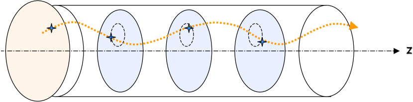
VI.3 Conceptual design
Figure 47 shows the layout under consideration for MICE, which is based on two cells of the Feasibility Study II “Lattice 1” cooling channel. The incoming muon beam encounters first a beam preparation section, where the appropriate input emittance is generated by a pair of high- (lead) absorbers. In addition, a precise time measurement is performed and the incident particles are identified as muons. There follows a first measurement section, in which the momenta, positions, and angles of the incoming particles are measured by means of tracking devices located within a uniform-field solenoid. Then comes the cooling section itself, with hydrogen absorbers and 201 MHz rf cavities, the lattice optics being provided by a series of superconducting coils; the pairs of coils surrounding each absorber have opposite magnetic fields (“bucking” solenoids), providing tight focusing. The momenta, positions, and angles of the outgoing particles are measured within a second solenoid, equipped with a tracking system identical to the first one. Finally, another time-of-flight (TOF) measurement is performed together with particle identification to eliminate those muons that have decayed within the apparatus.
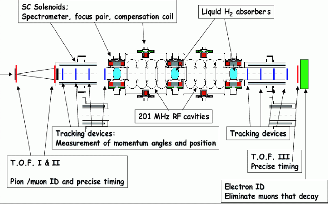
VI.4 Performance
Simulations of MICE have been carried out for a configuration including four tracking stations per spectrometer, each station consisting of three crossed planes of 500-micron-thick square-cross-section scintillating fibers (Figure 48), immersed in a 5 T solenoidal field. Time of flight is assumed to be measured to 70 ps rms. As shown in Figure 49, measurement resolution and multiple scattering of the muons in the detector material introduce a correctable bias in the measured emittance ratio of only 1%. (For this study the effect of the cooling apparatus was “turned off” so as to isolate the effect of the spectrometers.)
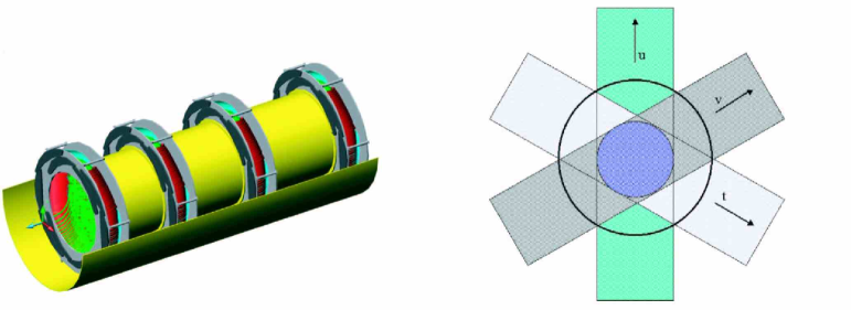
Figure 50 illustrates the muon-cooling performance of the proposed MICE cooling apparatus. The normalized transverse emittance of the incoming muon beam is reduced by about 8%. The longitudinal emittance increases by about the same amount, thus the net cooling in six dimensions is also about 8%. These are large enough effects to be straightforwardly measured by the proposed spectrometers.

The CERN Neutrino Factory Working Group has studied a variant of the proposed MICE cooling apparatus, in which 88-MHz rf cavities are employed in place of the 201-MHz devices (the 88- and 201-MHz designs have similar cooling performance) Hanke-cooling . Figure 51 (from the CERN study) elucidates further experimental issues. As shown in Figure 51a, for input emittance above the equilibrium emittance of the channel (here about 3500 mmmrad), the beam is cooled, while for input emittance below equilibrium it is heated (and, of course, for an input beam at the equilibrium emittance, the output emittance equals the input emittance). Figure 51b illustrates the acceptance cutoff of the cooling-channel lattice; for input emittance above 6000 mmmrad, the transmission probability falls below 100% due to scraping of the beam. Figure 51c shows the effect of varying the beam momentum: cooling performance improves as the momentum is lowered 333Despite the increased cooling efficiency at low muon momentum, simulations of an entire muon production section and cooling channel suggest that momenta near the ionization minimum represent the global optimum for Neutrino Factory performance., as quantified here in terms of the fractional increase in the number of muons within the phase-space volume accepted by a hypothetical acceleration section downstream of the cooling channel. The goal of MICE includes verification of these effects in detail in order to show that the performance of the cooling apparatus is well understood. Subsequent running could include tests of additional transverse cooling cells, alternative designs, or emittance exchange cells.
One critical aspect of this experiment is operation in the presence of backgrounds due to dark currents from the rf cavities. While it is possible to operate the experiment using comparatively low rf gradients, it would be highly desirable to produce cavities which would yield less dark current at higher gradients. This would permit more efficient use of the rf cavities and power supplies. We are trying to develop cavities with low dark currents.
VII Conclusions
In summary, the Muon Collaboration is developing the knowledge and ability to create, manipulate, and accelerate muon beams. Our R&D program will position the HEP community such that, when it requires a Neutrino Factory or a Muon Collider, we shall be in a position to provide it. A staged plan for the deployment of a Neutrino Factory has been developed that provides an active neutrino and muon physics program at each stage. The requisite R&D program is diversified over laboratories and universities and has international participation.
The very fortuitous situation of having intermediate steps along this path, that offer a powerful and exciting physics program in their own right, presents an ideal scientific opportunity, and it is hoped that the particle physics community will be able to take advantage of it.
References
-
(1)
SNO Collab., Q. R. Ahmad et al.,
Direct Evidence for Neutrino Flavor Transformations from
Neutral Current Interactions in the Sudbury Neutrino Observatory,
nucl-ex/0204008;
Q. R. Ahmad et al., Measurement of Day and Night Neutrino Energy Spectra at SNO and Constraints on Neutrino Mixing Parameters, nucl-ex/0204009;
Q. R. Ahmad et al., Measurement of the Rate of Interactions by 8B Neutrinos at the Sudbury Neutrino Observatory, Phys. Rev. Lett. 87, 071301 (2001). - (2) Super-Kamiokande Collab., Y. Fukuda et al., Phys. Lett. B433, 9 (1998); Phys. Lett. B436, 33 (1998); Phys. Rev. Lett. 81, 1562 (1998); Phys. Rev. Lett. 82, 2644 (1999).
- (3) The MC collaboration website is at http://www.cap.bnl.gov/mumu/.
- (4) G. I. Budker, in Proceedings of the 7th International Conf. on High Energy Accelerators, Yerevan (1969) p.33; extract in Physics Potential and Development of Colliders: Second Workshop, ed. D. Cline, AIP Conf. Proc. 352, 4 (1996).
- (5) A. N. Skrinsky, Proceedings of the International Seminar on Prospects of High-Energy Physics, Morges, 1971 (unpublished); extract in Physics Potential and Development of Colliders: Second Workshop, ed. D. Cline, AIP Conf. Proc. 352, 6 (1996).
- (6) A. N. Skrinsky and V. V. Parkhomchuk, Sov. J. Part. Nucl. 12, 223 (1981).
- (7) D. Neuffer, Particle Accelerators 14, 75 (1983).
- (8) R. B. Palmer, D. Neuffer, and J. Gallardo, A Practical High-Energy High-Luminosity Collider, Advanced Accelerator Concepts: 6th Annual Conference, ed. P. Schoessow, AIP Conf. Proc. 335, 635 (1995); D. Neuffer and R. B. Palmer, Progress Toward a High-Energy, High-Luminosity Collider, The Future of Accelerator Physics: The Tamura Symposium, ed. T. Tajima, AIP Conf. Proc. 356, 344 (1996).
- (9) Charles M. Ankenbrandt et al. (Muon Collider Collaboration), Phys. Rev. ST Accel. Beams 2, 081001 (1999), http://prst-ab.aps.org/abstract/PRSTAB/v2/i8/e081001
- (10) Muon-Muon Collider: A Feasibility Study, BNL-52503, Fermilab Conf-96/092, LBNL-38946 (1996).
- (11) Mucool Notes, http://www-mucool.fnal.gov/notes/notes.html.
- (12) D. Koshkarev, CERN/ ISR-DI/74-62 (1974).
- (13) B. J. King,The Physics Opportunities and Technical Challenges of a Muon Collider, Jan 1994, submitted to Columbia Unversity in partial fulfillment of the requirements of a Ph.D, physics/9907026, unpublished.
- (14) Proceedings of the Fermilab Workshop on Physics at a Muon Collider and the Front End of a Muon Collider, eds.-S. Geer, R. Raja (Nov. 1997), AIP Conf. Proc. 435; S. Geer, Physics Potential of Neutrino Beams from Muon Storage Rings, AIP Conf. Proc. 435, 384 (1998).
- (15) S. Geer, Phys. Rev. D 57, 6989 (1998).
- (16) D.A.Harris and Kevin McFarland,in rajageer , hep-ex/9804009, hep-ex/9804010; B. J. King,hep-ex/9907035; I. Bigi et al.,hep-ph/0106177.
- (17) NuFact99, Lyon, France, http://lyoinfo.in2p3.fr/nufact99/. Proceedings published in Nucl. Inst. Meth.A4451 (2000)
- (18) NuFact00, Monterey, California, http://www.lbl.gov/Conferences/nufact00/. Proceedings published in Nucl. Inst. Meth.A472 (2000)
- (19) NuFact01, Tsukuba, Japan, http://psux1.kek.jp/ nufact01/index.html.
- (20) NuFact02,Imperial College London, http://www.hep.ph.ic.ac.uk/NuFact02/
- (21) NuFact03, Columbia University, New York http://www.cap.bnl.gov/nufact03
- (22) Neutrino Factory and Muon Storage Rings at CERN http://muonstoragerings.web.cern.ch/muonstoragerings/
- (23) The Japanese Neutrino Factory http://www-prism.kek.jp/nufactj/
- (24) The MICE proposal can be found at http://hep04.phys.iit.edu/cooldemo/notes/notes.html
-
(25)
MUCOOL home page
http://www.fnal.gov/projects/muon_collider/cool/cool.html;
http://hepunx.rl.ac.uk/~edgecock/muons/muscat.html;
Emittance exchange home page
http://www.fnal.gov/projects/muon_collider/eexchange/;
Targetry home page
http://www.hep.princeton.edu/mumu/target/. - (26) N. Holtkamp and D. Finley, eds., A Feasibility Study of a Neutrino Source Based on a Muon Storage Ring, Fermilab-Pub-00/108-E (2000), http://www.fnal.gov/projects/muon_collider/nu-factory/nu-factory.html.
- (27) C. Albright et al., Physics at a Neutrino Factory, Fermilab FN692 (2000), hep-ex/0008064; http://www.fnal.gov/projects/muon_collider/nu/study/study.html.
- (28) V. Barger, R. Bernstein, A. Bueno, M. Campanelli, D. Casper, F. DeJongh, S. Geer, M. Goodman, D. A. Harris, K. S. McFarland, N. Mokhov, J. Morfin, J. Nelson, F. Peitropaolo, R. Raja, J. Rico, A. Rubbia, H. Schellman, R. Shrock, P. Spentzouris, R. Stefanski, L. Wai, and K. Whisnant, FERMILAB-FN-703, hep-ph/0103052.
- (29) S. Ozaki, R. Palmer, M. S. Zisman, and J. Gallardo, Editors, Feasibility Study-II of a Muon-Based Neutrino Source, BNL-52623 (June 2001); http://www.cap.bnl.gov/mumu/studyii/FS2-report.html.
- (30) UNO Official Home Page, http://superk.physics.sunysb.edu/uno/.
- (31) LANDD – A Massive Liquid Argon Detector for Proton Decay, Supernova, and Solar Neutrino Studies, and a Neutrino Factory Detector, D. B. Cline, F. Sergiampietri, J. G. Learned, and K. McDonald, astro-ph/0105442; K. T. McDonald, hep-ex/0204037; D. Ayres et al., physics/9911009; An early proposal for a liquid argon detector, ARGONAUT, may be found in G. Harigel, H. Kautzky,P. McIntyre, and A. Van Ginneken, Fermilab Proposal No. 601D, 1978.
- (32) F. Arneodo et al., Study of Solar Neutrinos with the 600-T Liquid Argon ICARUS Detector, Nucl. Instrum. Meth. A455, 376 (2000).
- (33) Some of the text quoted here appears in the Study II document EPP:studyii . We would like to thank Robert Shrock for helpful comments.
- (34) Fits and references to the Homestake, Kamiokande, GALLEX, SAGE, Super Kamiokande, and SNO data include N. Hata and P. Langacker, Phys. Rev. D 56, 6107 (1997); J. Bahcall, P. Krastev, and A. Smirnov, Phys. Rev. D 58, 096016 (1998); J. Bahcall and P. Krastev, Phys. Lett. B436, 243 (1998); J. Bahcall, P. Krastev, and A. Smirnov, Phys. Rev. D 60, 093001 (1999); J. Bahcall, P. Krastev, and A. Smirnov, hep-ph/0103179; M. Gonzalez-Garcia, C. Peña-Garay, and J. W. F. Valle, Phys. Rev. D 63, 013007; M. Gonzalez-Garcia et al., Phys. Rev. D 63, 033005 (2001); V. Barger, D. Marfatia, K. Whisnant, and B. P. Wood, Phys. Rev. D 64, 073009 (2001); P. Krastev and A. Smirnov, Phys. Rev. D 65, 073022 (2002); J. N. Bahcall, M. C. Gonzalez-Garcia, and C. Peña-Garay, hep-ph/0111150; M. Maltoni, T. Schwetz, and J. W. F. Valle, Phys. Rev. D 65, 093004 (2002). Recent discussions of flux calculations are found in J. Bahcall, Phys. Rept. 333, 47 (2000), hep-ph/0009044 talk at Neutrino-2000, and http://www.sns.ias.edu/jnb/; V. Barger, D. Marfatia, and K. Whisnant, Phys. Rev. Lett. 88, 011302 (2002); V. Barger, D. Marfatia, and K. Whisnant, Phys. Lett. B509, 19 (2001); V. Barger, D. Marfatia, K. Whisnant, and B. P. Wood, hep-ph/0204253. Super Kamiokande data are reported and analyzed in Y. Fukuda et al. (SuperKamiokande Collab.), Phys. Rev. Lett. 82, 1810 (1999); S. Fukuda et al., Phys. Rev. Lett. 86, 5651 (2001), Phys. Rev. Lett. 86, 5651 (2001). For recent reviews, see e.g., Y. Suzuki, talk at Neutrino-2000, Nucl. Phys. Proc. Suppl. 91, 29 (2001), http://www.nrc.ca/confserv/nu2000/; Y. Takeuchi at ICHEP-2000, Int’l Conf. on High Energy Physics, Osaka, http://ichep2000.hep.sci.osaka-u.ac.jp; and talks at the Fifth Topical Workshop at the Gran Sasso National Laboratory: Solar Neutrinos (Mar. 2001).
- (35) L. Wolfenstein, Phys. Rev. D 17, 2369 (1978).
- (36) V. Barger, K. Whisnant, S. Pakvasa, and R. J. N. Phillips, Phys. Rev. D 22, 2718 (1980).
- (37) V. Barger et al., Phys. Rev. D 22, 1636 (1980).
- (38) S. P. Mikheyev and A. Smirnov, Yad. Fiz. 42, 1441 (1985) [Sov. J. Nucl. Phys. 42, 913 (1986)], Nuovo Cim., C9, 17 (1986); S. P. Rosen and J. Gelb, Phys. Rev. D 34, 969 (1986); S. Parke, Phys. Rev. Lett. 57, 1275 (1986); W. Haxton, Phys. Rev. Lett. 57, 1271 (1986); T. K. Kuo and J. Pantaleone, Rev. Mod. Phys. 61, 937 (1989).
- (39) V. Barger, R. J. N. Phillips, and K. Whisnant, Phys. Rev. D 24, 538 (1981); S. L. Glashow and L. M. Krauss, Phys. Lett. B190, 199 (1987).
- (40) Kamiokande Collab., K. S. Hirata et al.,, Phys. Lett. B205, 416 (1988); Phys. Lett. B280, 146 (1992); Y. Fukuda et al., Phys. Lett. B335, 237 (1994); S. Hatakeyama et al., Phys. Rev. Lett. 81, 2016 (1998).
- (41) IMB Collab., D. Casper et al., Phys. Rev. Lett. 66, 2561 (1991); R. Becker-Szendy et al., Phys. Rev. D 46, 3720 (1992); Phys. Rev. Lett. 69, 1010 (1992).
- (42) Y. Fukuda et al., Phys. Lett. B433, 9 (1998); Phys. Rev. Lett. 81,1562 (1998); Phys. Rev. Lett. 82, 2644 (1999); Phys. Lett. B467, 185 (1999); H. Sobel, in Neutrino-2000, Nucl. Phys. Proc. Suppl. 91, 127 (2001); T. Toshito, in ICHEP-2000. Recent discussions of flux calculations are in T. Gaisser, Nucl. Phys. Proc. Suppl. 87, 145 (2000); P. Lipari, Astropart. Phys. 14, 153 (2000); G. Battistoni, hep-ph/0012268; G. Fiorentini, V. Naumov, and F. Villante, Phys. Lett. B510, 173 (2001).
- (43) W. Allison et al., Phys. Lett. B449, 137 (1999); A. Mann, talk at Neutrino-2000, hep-ex/0007031.
- (44) M. Ambrosio et al., Phys. Lett. B478, 5 (2000); B. Barish, talk at Neutrino-2000, Nucl. Phys. Proc. Suppl. 91, 141 (2001).
- (45) M. Apollonio et al., Phys. Lett. B420, 397 (1998); Phys. Lett. B466, 415 (1999).
- (46) LSND Collab., C. Athanassopoulous et al., Phys. Rev. Lett. 77, 3082 (1996); Phys. Rev. Lett. 81, 1774 (1998); K. Eitel, in Neutrino-2000.
- (47) KARMEN Collab., K. Eitel, in Proceedings of Neutrino-2000, Nucl. Phys. Proc. Suppl. 91, 191 (2000).
- (48) References and websites for these experiments and future projects can be found, e.g., at http://www.hep.anl.gov/ndk/hypertext/nu_industry.html.
- (49) M. Sakuda and K. Nishikawa, talks at ICHEP-2000, Osaka; S. H. Ahn et al., Phys. Lett B511, 178 (2001).
- (50) OPERA Collab., CERN-SPSC-97-24, hep-ex/9812015.
-
(51)
ICARUS/ICANOE Collab. F. Cavanna et al.,
LNGS-P21-99-ADD-1,2 (Nov 1999);
A. Rubbia, hep-ex/0001052. - (52) V. Barger, A. M. Gago, D. Marfatia, W. J. Teves, B. P. Wood, and R. Zukanovich Funchal, Phys. Rev. D 65, 053016 (2002).
- (53) Y. Itoh et al., (JHF Neutrino Working Group), Letter of Intent: A Long Baseline Neutrino Oscillation Experiment using the JHF 50 GeV Proton Synchrotron and the Super-Kamiokande Detector (Feb. 2000).
- (54) V. D. Barger, D. Marfatia, and K. Whisnant, Phys. Rev. Lett. 88, 011302 (2002).
- (55) P. Alivisatos et al., STANFORD-HEP-98-03; http://www.awa.tohoku.ac.jp/KamLAND.
- (56) V. D. Barger, D. Marfatia, and B. P. Wood, Phys. Lett. B498, 53 (2001).
- (57) K. Eguchi et al. [KamLAND collaboration], Phys. Rev. Lett. 90, 021802 (2003).
- (58) V. Barger and D. Marfatia, Phys. Lett. B555 , 144 (2003).
- (59) G.L. Fogli, E. Lisi, A. Marrone, D. Montanino, A. Palazzo, and A.M. Rotunno, Phys. Rev. D67, 073002 (2003).
- (60) Z. Parsa, in Proceedings of NNN99, AIP Conf. Proc. 533, 181 (1999).
- (61) A. De Rujula, M. B. Gavela, and P. Hernandez, Nucl. Phys. B547, 21 (1999).
- (62) V. Barger, K. Whisnant, and R. J. N. Phillips, Phys. Rev. Lett. 45, 2084 (1980).
-
(63)
L. Sulak, in First Workshop on Grand
Unification (Math
Sci. Press, 1980), p. 163;
D. Ayres, T. Gaisser, A. K. Mann, and R. Shrock, in Proceedings of the 1982 DPF Summer Study on Elementary Particles and Future Facilities, Snowmass, p. 590; D. Ayres, B. Cortez, T. Gaisser, A. K. Mann, R. Shrock, and L. Sulak, Phys. Rev. D 29, 902 (1984). - (64) P. Krastev and S. Petcov, Phys. Lett. B205, 84 (1988).
- (65) A. J. Baltz and J. Weneser, Phys. Rev. D 37, 3364 (1988).
- (66) S. Petcov, Phys. Lett. B434, 321 (1998); M. Chizhov, M. Maris, and S. Petcov, hep-ph/9810501; M. Chizhov and S. Petcov, Phys. Rev. D 63, 073003 (2001); M. Chizhov and S. Petcov, Phys. Rev. Lett. 83, 1096 (1999).
-
(67)
E. Akhmedov, A. Dighe, P. Lipari, and A. Smirnov,
Nucl. Phys. B542, 3 (1999);
E. Akhmedov, Nucl. Phys. B538, 25 (1999); hep-ph/0001264. -
(68)
P. Krastev, Nuovo Cimento 103A, 361 (1990);
R. H. Bernstein and S. J. Parke, Phys. Rev. D 44, 2069 (1991). - (69) V. Barger, S. Geer, and K. Whisnant, Phys.Rev. D 61, 053004 (2000).
- (70) I. Mocioiu and R. Shrock, Phys. Rev. D 62, 053017 (2000); Proceedings of NNN99, AIP Conf. Proc. 533, 74 (1999); I. Mocioiu and R. Shrock, JHEP 0111, 050 (2001).
- (71) V. Barger, S. Geer, R. Raja, and K. Whisnant, Phys. Rev. D 62, 013004 (2000).
- (72) V. Barger, S. Geer, R. Raja, and K. Whisnant, Phys. Rev. D 62, 073002 (2000).
-
(73)
V. Barger, S. Geer, R. Raja, and K. Whisnant,
Phys. Lett. B485, 379 (2000);
Phys. Rev. D 63, 033002 (2001). - (74) A. Cervera, A. Donini, M. B. Gavela, J. Gomez Cadenas, P. Hernandez, O. Mena, and S. Rigolin, Nucl. Phys. B579, 17 (2000), Erratum-ibid. B593, 731 (2001).
- (75) M. Freund and T. Ohlsson, Mod. Phys. Lett. A15, 867 (2000); T. Ohlsson and H. Snellman, J. Math. Phys. 41, 2768 (2000); Phys. Rev. D 60 093007 (1999); Phys. Lett. B474, 153 (2000); M. Freund, M. Lindner, S. Petcov, and A. Romanino, Nucl. Phys. B578, 27 (2000); M. Freund, P. Huber, and M. Lindner, Nucl. Phys. B585, 105 (2000); M. Freund, M. Lindner, and S. Petcov. Nucl. Instrum. Meth. A451, 18 (2000); K. Dick, M. Freund, P. Huber, and M. Lindner, Nucl. Phys. B588, 101 (2000); Nucl. Phys. B598, 543 (2001).
-
(76)
S. M. Bilenky, C. Giunti, and W. Grimus, Phys. Rev. D 58,
033001 (1998);
K. Dick, M. Freund, M. Lindner, and A. Romanino, Nucl. Phys. B562, 29 (1999);
M. Tanimoto, Phys. Lett. B462, 115 (1999);
A. Donini, M. B. Gavela, and P. Hernandez, Nucl. Phys. B574, 23 (2000);
M. Koike and J. Sato, Phys. Rev. D 61 073012 (2000); Erratum-ibid. D 62, 079903 (2000);
M. Koike and J. Sato, Phys. Rev. D 62, 073006 (2000);
M. Koike, T. Ota, and J. Sato, Phys. Rev. D 65, 053015 (2002);
F. Harrison, and W. G. Scott, Phys. Lett. B476, 349 (2000). -
(77)
M. Freund, Phys. Rev. D 64, 053003 (2001);
V. Barger, D. Marfatia, and K. Whisnant, Phys. Rev. D 65, 073023 (2002). - (78) T. Yanagida, Baryon Asymmetry from Leptonic CP Violation, presented at NuFACT’01, Tsukuba, Japan (24–30 May 2001), http://psux1.kek.jp/nufact01/index.html.
- (79) V. Barger, S. Geer, R. Raja, and K. Whisnant, Phys. Rev. D 63, 113011 (2001).
- (80) V. Barger, D. Marfatia, and K. Whisnant, hep-ph/0108090.
- (81) See http://www-bd.fnal.gov/pdriver.
- (82) M. L. Mangano et al., Physics at the Front-End of a Neutrino Factory: A Quantitative Appraisal, CERN-TH/2001-131, hep-ph/0105155.
- (83) E. P. Hincks and B. Pontecorvo, Phys. Rev. 73, 257 (1948).
- (84) R. L. Garwin, L. M. Lederman, and M. Weinrich, Phys. Rev. 105, 1415 (1957).
- (85) Y. Semertzidis, Talk given at ICHEP02, Amsterdam, 31 July 2002, http://www.ichep02.nl/index-new.html; for earlier result see H.N. Brown et al., Phys. Rev. Lett. 86, 2227 (2001) and references therein
- (86) R. Edgecock, “Summary of Muon Beams Around the World,” presented at the Workshop on Instrumentation for Muon Cooling Studies, Illinois Institute of Technology, Chicago, IL 60616 USA (10–11 Nov. 2000), http://www.iit.edu/bcps/hep/Nov2000_mucool.html.
- (87) Y. K. Semertzidis et al., in Proc. Int. Workshop on High Intensity Muon Sources (HIMUS99), KEK, Tsukuba, Japan (1–4 Dec. 1999).
- (88) R. M. Carey et al., “An Improved Limit on the Muon Neutrino Mass from Pion Decay in Flight,” Proposal to Brookhaven (17 Aug. 2000).
- (89) J. Aysto et al, CERN-TH/2001-231 and hep-ph/0109217
- (90) W. Marciano, in Proc. Workshop on the First Muon Collider and at the Front End of the Muon Collider, S. Geer and R. Raja, eds., Fermilab, Batavia, IL (Nov. 1997), AIP Conf. Proc. 435, 58 (1998).
- (91) James L. Popp et al., hep-ex/0101017
- (92) W. Honnecker et al., Phys. Rev. Lett. 76, 200 (1996);
- (93) M. L. Brooks et al., Phys. Rev. Lett. 83, 1521 (1999).
- (94) M. Cooper, in Proc. Workshop on the First Muon Collider and at the Front End of the Muon Collider, AIP Conf. Proc. 435, 443 (1998).
- (95) T. Mori et al. proposal to PSI R-99-05 (1999)
- (96) R. M. Carey et al., “AGS Letter of Intent – Search for a Permanent Muon Electric Dipole Moment,” (2 Feb. 2000); see also Y. Semertzidis et al., J. Mod. Phys. A 16, 287 Suppl. 1B (2001)
- (97) J. Ellis et al, hep-ph/0111324; see also K.S. Babu et al., hep-ph/0006329
- (98) J. Kirkby et al., PSI proposal R-99-06 (1999); D.W. Hertzog et al., PSI proposal R-99-07 (1999); K. Nagamine et al., RIKEN-RAL muon lifetime experiment (1998)
- (99) D. E. Groom et al., Eur. Phys. J. C15 (2000) 1 and 2001 off-year partial update for the 2002 edition available on the PDG WWW pages (URL: http://pdg.lbl.gov/).
- (100) M. Aoki, presented at NuFACT‘01, Tsukuba, Japan (24–30 May 2001).
- (101) F.J.M. Farley and E. Picasso, in: Quantum Electrodynamics, T. Kinoshita (ed.), World Scientific, Singapore, p. 479 (1990); V.W. Hughes and T. Kinoshita, in: Muon Physics I, V. W. Hughes and C.S. Wu (eds.), Academic Press, New York, pp. 12-199 (1977)
- (102) M. Knecht and A. Nyffeler, Phys. Rev. D 65, 073034 (2002); M. Knecht et al., Phys. Rev. Lett. 88, 071802 (2002); M. Hayakawa and T. Kinoshita, hep-ph /0112102 (2001); J. Bijnens et al., Nucl. Phys. B 626, 410 (2002); I. Blokland, Phys. Rev. Lett. 88, 071803 (2002)
- (103) A. Czarnecki and W.Marciano, hep-ph/0102122 (2001) (2000)
- (104) W. Marciano and B.L. Roberts, hep-ph/0105056 (2001)
- (105) R. Bluhm, V.A. Kostelecky and C.D. Lane, Phys. Rev. Lett. 84, 1098 (2000)
- (106) D. Kawall et al., in Proc. Workshop on the First Muon Collider and at the Front End of the Muon Collider, AIP Conf. Proc. 435, 486 (1998).
- (107) K. Jungmann, The Hydrogen Atom, S. Karshenboin et al. (eds.), Springer, Heidelberg, 81 (2001).
- (108) W. Molzon, in Proc. Workshop on the First Muon Collider and at the Front End of the Muon Collider, AIP Conf. Proc. 435, 152 (1998).
- (109) W. Liu, et al., Phys. Rev. Lett. 82, 711 (1999).
- (110) V. Meyer et al., Phys. Rev. Lett. 84, 1136 (2000)
- (111) V.W. Hughes et al., Phys. Rev. Lett. 5, 63 (1960)
- (112) L. Willmann et al., Phys. Rev. Lett. 82, 49 (1999); R. Abela et al., Phys. Rev. Lett. 77, 1950 (1996).
- (113) P.Strasser and K. Nagamine, Hyperfine Interactions, in print (2002)
- (114) J. Dilling et al., Hyperf. Interact. 127, 491 (2000)
- (115) G.L. Borchert et al. , Acta Physica Polonica B 29, 131 (1998)
- (116) R. Hayano, Workshop on ”Radioactive Antiprotonic and Muonic Atoms”, CERN ISOLDE group (contact: Juha Aysto), Switzerland (2001)
- (117) The material on the Higgs Factory physics is excerpted from V. Barger, M. S. Berger, J. F. Gunion, and T. Han, Physics at Higgs Factories, Snowmass 2001, hep-ph/0110340.
- (118) D. B. Cline and G. Hanson, A Muon Collider as a Higgs Factory, Proceedings of Snowmass 2001, http://www.slac.stanford.edu/econf/C010630/papers/M103.PDF.
- (119) R. Raja and A. Tollestrup, Calibrating the Energy of a 50-GeV x 50-GeV Muon Collider Using Spin Precession, Phys. Rev. D 58, 013005 (1998).
- (120) V. Barger, M. S. Berger, J. F. Gunion, and T. Han, Phys. Rept. 286, 1 (1997).
-
(121)
V. Barger, M. S. Berger, J. F. Gunion, and T. Han,
Phys. Rev. Lett. 75, 1462 (1995);
V. Barger, T. Han, and C. G. Zhou, Phys. Lett. B480, 140 (2000). - (122) M. Battaglia and K. Desch, hep-ph/0101165.
- (123) J. F. Gunion, L. Poggioli, R. Van Kooten, C. Kao, and P. Rowson, hep-ph/9703330.
- (124) S. Ahn et al., Muon Colliders: A Scenario for the Evolution of the Fermilab Accelerator Complex, Fermilab-FN-677 (1999).
- (125) V. Barger, M. S. Berger, J. F. Gunion, and T. Han, Phys. Rev. D 56, 1714 (1997).
- (126) M. S. Berger, “Precision W Boson and Higgs Boson Mass Determination at Muon Colliders,” in Proceedings of the Fermilab Workshop on Physics at a Muon Collider and the Front End of a Muon Collider, editors- S. Geer, R. Raja (November 1997) AIP 435, hep-ph/9712474.
- (127) M. S. Berger, The Top-Antitop Threshold at Muon Colliders in Proceedings of the Fermilab Workshop on Physics at a Muon Collider and the Front End of a Muon Collider, editors- S. Geer and R. Raja (November 1997) AIP 435, hep-ph/9712486.
- (128) B. J. King, Proc. PAC’99, pp318-20, New York City, NY, U.S.A, 29Mar-2 Apr 1999. Physics/9908017; N. V. Mokhov,A. Van Ginneken,ibid. pp.3074-3076, Fermilab-Conf-99/067 N. V. Mokhov,A. Van Ginneken, Proc. ICRS-9 Int. Conf. on Radiation Shielding, Tsukuba 1999, J. Nucl. Sci. Technology, pp.172-179 (2000), Fermilab-Conf-00/065.; B.J.King, Proc. HEMC99, pp. 165-180, Montauk, NY, 27 Sep-1 Oct 1999, AIP Conf. Proc. Vol. 530, ed. B. J. King,hep-ex/0005006;
- (129) W. Chou, A. Ankenbrandt, and E. Malamud, The Proton Driver Design Study, FERMILAB-TM-2136 (December 2000).
- (130) Proc. 1999 Particle Accelerator Conference, New York(IEEE,New York,1999). http://accelconf.web.cern.ch/AccelConf/p99/procs.htm
- (131) Proc. 2001 Particle Accelerator Conference, Chicago (IEEE, New York, 2001) http://accelconf.web.cern.ch/AccelConf/p01/
- (132) N. Mokhov, Particle Production and Radiation Environment at a Neutrino Factory Target Station, Fermilab-Conf-01/134 (2001),see pac2001 p 745; http://www-mucool.fnal.gov/mcnotes/public/ps/muc0194/muc0194.ps.gz N. Mokhov, http://www-ap.fnal.gov/MARS/; nucl-th/9812038.
- (133) R. J. Jayakumar et al., The USHT-ITER CS Model Coil Program Achievements, IEEE Trans. Appl. Supercond. 10, 1 (2000).
- (134) J. R.Haines and C. C. Tsai, Graphite Sublimation Tests for the Muon Collider/Neutrino Factory Target Development Program, ORNL/TM-2002/27 (Feb 2002).
- (135) M. J. Burns et al., DARHT Accelerators Update and Plans for Initial Operation,see pac1999 p. 617.
- (136) The GEANT4 Tool Kit is available at http://wwwinfo.cern.ch/asd/geant4/geant4.html.
- (137) Fermilab Proton Driver Physics Study Website is at http://projects.fnal.gov/protondriver/.
- (138) Proceedings of the Workshop on a Low-Energy Storage Ring (pbar2000) D. M. Kaplan, H. A. Rubin, and K. Seth, eds., Illinois Institute of Technology, Chicago, IL (2001), http://www.iit.edu/bcps/hep/pbar2000.html.
- (139) G. Hanson,Towards the Higgs Factory/Muon Collider, plenary talk at NUFACT01, Tsukuba, Japan (2001) nufact01 .
-
(140)
Higgs Factory Report, D. Cline and G. Hanson,
eds.,submitted to Snowmass 2001
http://www.physics.ucla.edu/snowmass/. -
(141)
“Emittance Exchange Workshop, Brookhaven National Laboratory”
Sep. 2000,
http://www.cap.bnl.gov/mumu/exchange/;
“Workshop on Instrumentation on Muon Cooling Studies”, IIT, November 2000, http://www.capp.iit.edu/~capp/workshops/muinst2000/raja.pdf - (142) “Workshop on Ring Coolers and Emittance Exchange”, Lawrence Berkeley Lab (3-16 October 2001), http://www.fnal.gov/projects/muon_collider/eexchange/workshop/ee_agenda.htm.
- (143) V. Balbekov, S. Geer, N. Mokhov, R. Raja, and Z. Usubov, “Muon Ring Cooler for the MUCOOL Experiment”,see pac2001 , p 3867.
-
(144)
V. Balbekov, “Solenoid Based Ring Coolers” (February 2002),
http://www.capp.iit.edu/~capp/workshops/mumice02/mumice02_schedule.html. -
(145)
R. Fernow, A Simulation Code for Ionization Cooling
of Muon Beams, see pac1999 p. 3020,
http://pubweb.bnl.gov/people/fernow/. -
(146)
R. Palmer, “Muon Cooling Rings and Kickers” (January 2002),
http://pubweb.bnl.gov/people/palmer/exch/kicker2.pdf. - (147) D. Neuffer, “Injection/Extraction and a Ring Cooler,” Mucool Note 211, http://www-mucool.fnal.gov/mcnotes/public/pdf/muc0211/muc0211.pdf.
-
(148)
S.Kahn et.al, “Design of a Magnet System for a Muon Cooling Ring Experiment”, Proc. 2001 Particle Accelerator Conference, Chicago, June 2001, P.3239
http://accelconf.web.cern.ch/AccelConf/p01/PAPERS/RPPH010.PDF - (149) The working group on the quadrupole ring cooler consists of Y. Fukui, D. Cline, A. Garren, P. He (UCLA), A. Bogacz(Jefferson Lab), D. Errede(UIUC), H. Kirk(BNL), and F. Mills(Fermilab).
- (150) G. I. Budker and A. N. Skrinsky, Sov. Phys. Usp. 21, 277 (1978).
- (151) H. Kirk, D. Cline, Y, Fukui, and A. Garren Progress Toward a Muon Ring Cooler, Accelerator M1 Working Group Report, Snowmass 2001 Workshop, Snowmass, Colorado, 2001. http://www.slac.stanford.edu/econf/C010630/papers/M101.PDF
- (152) A. A. Garren, A. S. Kenney, E. D. Courant, A. D. Russel, and M. J. Syphers SYNCH - A Computer System for Synchrotron Design and Orbit Analysis, User’s Guide, SSCL-MAN-0030 (1993).
- (153) Proc. HEMC’99 Studies on Collider and Collider Physics at the Highest Energies: Muon Colliders at 10 TeV to 100TeV, Montauk, NY, 27 Sep-1 Oct 1999; AIP. Conf.Proc. Vol. 530, ed B.J. King; Muon Colliders at the High Energy Frontier Proceedings of the 6-Month Feasibility Study, Oct00-Apr01, eds. A. Caldwell and B. J. King, ISBN:1-58949-020-7, Rinton Press.
- (154) Muons, Inc. is a private corporation headed by Rolland Johnson that has received the DoE STTR grant to carry out this research. http://www-mucool.fnal.gov/mcnotes/public/ps/muc0247/muc0247.ps.gz
-
(155)
Chun-xi Wang and Kwang-Je Kim, Phys. Rev. Lett. 88, 184801 (2002);
Kwang-Je Kim and Chun-xi Wang, Phys. Rev. Lett. 85, 760 (2000);
G. Penn and J. S. Wurtele, Phys. Rev. Lett. 85, 764 (2000);
V. M. Malkin and N. J. Fisch, Phys. Rev. Lett. 85, 5575 (2000). -
(156)
J. Norem et al., “Preliminary Lab G Dark
Current
Results,” Mucool Note 226 (October 2001),
http://www-mucool.fnal.gov/mcnotes/public/pdf/muc0226/muc0226.pdf;
J. Norem, V. Wu, A. Moretti, M. Popovic, Z. Qian, L. Ducas, Y. Torun, and N. Solomey, Dark Current Measurements of a Multicell, 805 MHz Cavity, Mucool Note 235, submitted to Phys. Rev. Spec. Top. - Acc. and Beams.
http://www-mucool.fnal.gov/mcnotes/public/pdf/muc0235/muc0235.pdf - (157) Muon Technical Advisory Committee (H. Edwards et al.), “MUTAC Committee Report on the Muon Collaboration Review, 18–19 Oct. 2001” (2 Dec. 2001).
- (158) M. Aleska et. al, Beam Dynamics Study of a Muon Ionization Cooling Experiment, CERN-Nufact-Note-108, http://molat.home.cern.ch/molat/neutrino/nf108.pdf.
- (159) L. Cremaldi and D. Summers, Mucool Note 221 (October 2001), http://www-mucool.fnal.gov/mcnotes/public/pdf/muc0221/muc0221.pdf; D. Bartlett et al., Nucl. Instrum. Meth. A260, 55 (1987).
-
(160)
A. Blondel, contribution to the CERN Neutrino Factory Working Group,
http://nfwg.home.cern.ch/nfwg/nufactwg/38/blondel.PDF. - (161) K. Hanke, contribution to the Workshop on an International Muon Ionization Cooling Experiment, CERN, October 2001, http://muonstoragerings.cern.ch/October01WS/oct01ws.html.