Studies of aging and HV break down problems during development and operation of MSGC and GEM detectors for the Inner Tracking System of HERA-B
Abstract
The results of five years of development of the inner tracking system of the HERA-B experiment and first experience from the data taking period of the year 2000 are reported. The system contains 184 chambers, covering a sensitive area of about (20 20) cm2 each. The detector is based on microstrip gas counters (MSGCs) with diamond like coated (DLC) glass wafers and gas electron multipliers (GEMs). The main problems in the development phase were gas discharges in intense hadron beams and aging in a high radiation dose environment. The observation of gas discharges which damage the electrode structure of the MSGC led to the addition of the GEM as a first amplification step. Spurious sparking at the GEM cannot be avoided completely. It does not affect the GEM itself but can produce secondary damage of the MSGC if the electric field between the GEM and the MSGC is above a threshold depending on operation conditions. We observed that aging does not only depend on the dose but also on the spot size of the irradiated area. Ar-DME mixtures had to be abandoned whereas a mixture of 70% Ar and 30% CO2 showed no serious aging effects up to about 40 mC/cm deposited charge on the anodes. X-ray measurements indicate that the DLC of the MSGC is deteriorated by the gas amplification process. As a consequence, long term gain variations are expected. The Inner Tracker has successfully participated in the data taking at HERA-B during summer 2000.
keywords:
MSGC , MSGC-GEM , Gas aging , Discharges , HERA-BPACS:
29.40.G , 29.40.C , 07.85.F , 81.40.C , 52.801 Introduction
The HERA-B experiment [1] was designed with the goal to measure CP violation in the B-system. It started operation at DESY, Hamburg in spring 2000. Neutral B-Mesons are produced by interactions of 920 GeV protons on a stationary nuclear target followed by a magnetic spectrometer. Since the B cross section is very low, the experiment was planed for an interaction rate of 40 MHz to obtain an acceptable B production rate. The detectors therefore were designed to withstand the corresponding high particle rates and high radiation levels.
To cope with the high particle flux which drops roughly as one over the distance from the beam axis squared, the main tracking system has been subdivided into two parts with different rate capabilities: the Inner Tracker (ITR) near the beam pipe and at larger distance the Outer Tracker (OTR) consisting of drift chambers composed of honeycomb structures.
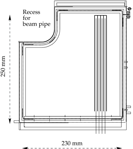
The outer dimensions of the sensitive area of the ITR are given by the requirement that the occupancy per channel of the OTR does not exceed a critical value of 20%. The high intensity area can be covered by four MSGC detectors with wafer size of 2525 cm2 which can be realized in industry. The basic geometry of a MSGC detector is shown in Figure 1. The detectors have a round recess which permits to position four MSGCs around the beam pipe. They have to sustain a particle flux of up to 2106/cm2/s and radiation doses of up to 1 Mrad/year. These requirements are very similar to those of the inner tracking in the ATLAS and CMS experiments for LHC and are a big challenge for the tracking detector technology.
The total HERA-B ITR system requires 46 detector planes, each consisting of four chambers. Each of the 184 chambers has 752 anode strips leading to a total of about 140000 readout channels. This basic design has remained unchanged, the detector technology, however, had to be modified several times as a consequence of R&D work and, especially, the results of beam tests.
At the time of approval of the experiment in 1995, the MSGC technology was claimed to be ready for high rate applications [2, 3, 4]. Very promising test results had been obtained and published with the claim that MSGCs on ordinary borosilicate glass wafers can be operated at high rates with good stability and homogeneous response. Moreover, aging tests with Ar-DME (argon-dimethylether) mixtures and clean gas systems were reported which were interpreted to demonstrate that these detectors can survive up to 10 years of LHC operation (equivalent to about the same time at HERA-B) without severe problems. Finally, the production of large size wafers with small error rate at rather low cost was promised.
The construction of an inner tracker for HERA-B based on the MSGC technology therefore looked rather straight forward when the experiment was approved. In the course of our development work we faced however several serious and unexpected problems:
-
•
The production of large size MSGC wafers 2525 cm2 with acceptable quality and a small fraction of broken anodes and cathodes turned out to be difficult. After extensive R&D at the company IMT111IMT, Greifensee, Switzerland, series production of these wafers now has high yield with less than 5% interrupted anodes and no shorts.
-
•
MSGCs based on bare glass (DESAG 263) wafers as proposed were unable to satisfy the requirements on gain homogeneity, rate stability and radiation tolerance. These problems were solved by the introduction of “diamond like coating” (DLC) which provides a well defined electronic surface conductivity of the substrate.
-
•
MSGCs with DLC exhibit gas discharges between anodes and cathodes when operated in a hadron beam at the required high gas gain. Every discharge damages electrodes and in the long run this effect leads to an intolerable number of broken anodes. This problem could be solved by the introduction of an additional amplification step using the GEM technology [5].
-
•
The MSGC/GEM technology is vulnerable. We have experienced a series of problems with gas discharges at the GEM which subsequently lead to damages of the MSGC electrodes.
-
•
Moreover, we were repeatedly faced with aging problems due to traces of impurities which are very hard to avoid reliably during production of a large series and during long term operation. Above all, the Ar-DME mixture originally foreseen as counting gas in most MSGC developments showed rapid aging in large area X-ray and test beam illumination of detectors. Finally, an Ar-CO2 mixture had to be used.
In the following, major development steps and the most important results are described.
2 The MSGC detector
2.1 Detector geometry
The electrode structure chosen for the MSGC (type A) has a pitch of 300 m, anode width of 10 m and an anode cathode gap of 60 m. 48 chambers (type B) located at the downstream end of the tracking have to cover a larger sensitive area. They have a pitch of 350 m allowing to use the same readout configuration as for the smaller chambers. The pitch is a compromise between cost of the electronics and maximum tolerable occupancy. The relatively large anode width was chosen to minimize the number of anodes interrupted during production. The maximum length of an anode in the experiment is 23 cm. The height of the drift gap was chosen to be 3.3 mm. This guarantees that all primary electrons have reached the anodes within 60 ns even for slow Ar-DME mixtures and that the anode signal occupies only one bunch crossing. Subsequent bunch crossings are 96 ns apart.
The high voltage is distributed via a resistor network to groups of 16 cathodes. In this way, a short between an anode and a cathode strip leads to an inefficient region of about 2 % of the total chamber area.
2.2 Wafers and coating
Experience with first prototypes of MSGCs [6] showed that bare glass with its relatively low ionic conductivity cannot be used in a high rate and high dose environment. Local gain variations up to a factor of three were found even at low counting rates. The gas gain was rate dependent and the detectors did not survive an X-ray dose equivalent to about half a HERA-B year. Glass with electronic conductivity was excluded both by cost and its short radiation length. The obvious solution was to coat the surface with an electronically conducting compound. Many different coatings have been tested by various groups. Finally, DLC proved to be adequate.
DLC surfaces had been developed simultaneously by the CERN group together with the company SURMET222SURMET Corporation, Burlington, MA, USA., and by the Siegen group together with a Fraunhofer Institut333Fraunhofer Institut für Schicht- und Oberflächentechnik, Braunschweig, Germany.. The two coatings are very similar in their chemical composition. They consist of mixtures of the elements C, Si, H, N deposited on the glass by chemical vapor deposition (CVD) using gas mixtures of CH4, SiH4, N2. In fact, the coating consists mainly of amorphous carbon and has very little diamond content, if any. The relative abundance of nitrogen and hydrogen and the production temperature determine the electric conductivity. Silicon improves the adhesion of the coating layer which has a typical thickness of 80 nm. The resistivity of the coating can be increased by tempering the wafers. Tempering also increases the stability of the resistivity with time. Wafers coated by SURMET were delivered with typical resistivity of whereas the resistivity of the Fraunhofer coating was originally lower by one to two orders of magnitude.
The SURMET coating had reasonable electrical properties and very good chemical stability. The mechanical quality of the large area coating was however not satisfactory most likely due to problems in handling and cleaning. For the main series production the DLC was therefore produced by the Fraunhofer Institut on AF45 glass (alkali “free”, produced by DESAG ). This type of glass with little alkali content was chosen to reduce the risk of electrolytic modifications of the substrate, caused by the continuous alkali ion current over several years [7]. The coating has an average surface conductivity of which varies over the area by about 20 %.
The lithographic production of the electrode pattern was realized by the company IMT on the coated wafers of 0.4 mm thickness and outer dimensions of about 3030 cm2.
To avoid overlapping hits in subsequent bunch crossings, we have to avoid electronic broadening of the signals propagating along the anode beyond about 50 ns. The signal shape at the amplifier input depends on the distance of the avalanche to the amplifier end of the anode and on the product of anode-cathode resistivity and capacitance. Delta shaped voltage pulses generated at the far end of the anode produce exponentially decaying signals at the amplifier input with a time constant , with the total anode resistance and the anode cathode capacitance. Thus the signal width is proportional to the strip length squared. For the given anode strip length of 23 cm and anode cathode capacitance of 20 pF an anode material of resistivity444The actual resistivity of lithographically produced electrodes is usually much higher than the nominal table values for bulk material. below 250 /cm is required. This requirement excludes nickel and chromium and points to aluminium or gold. Aluminium is preferable for lithography and has also rather good resistance to sparks (see Section 2.4). Aging tests with aluminium wafers however were discouraging (see Section 4). The aluminium option was therefore abandoned. A 500 nm thick gold MSGC pattern was produced by a lift-off technique.
The thickness of the different wafer materials is summarized in Table 1.
| material | AF45 | CVD | titanium | gold |
|---|---|---|---|---|
| glass substrate | coating | adhesion layer | electrode structure | |
| thickness | 400 | 0.080 | 0.050 | 0.500 |
After major improvements of the spinning techniques, of cleaning and etching processes and semi-automatic handling of the wafers, IMT was able to produce with high yield wafers with less than 5 % broken anodes. The number of faults was measured by a specially designed electrical test station [8]. If a short was found, the wafer was repaired by etching away the short. Accepted wafers had no shorts and an average of 2 % interrupted anodes.
2.3 Operation characteristics
Small size prototypes 10 10 cm2 of MSGCs with coated wafers were systematically tested. The homogeneity of the gas gain over the full area showed variations of less than 20 %. During a long series of aging tests, chambers operated with an argon dimethylether mixture of 50 % Ar and 50 % DME (Ar-DME 50/50) were illuminated with X-rays over typical areas of up to 113 mm2. The chambers showed constant gain up to charge depositions of 80 mC/cm corresponding to more than 10 years of HERA-B operation. Rate tests demonstrated that the detectors could be operated at gas gains of 3500 up to rates of absorbed X-quanta /mm2/s with a loss of pulse height of less than 40%. In laboratory measurements with a source, efficiencies above 99% were achieved. This type of MSGCs therefore promised good performance for HERA-B.
In the year 1996 a beam test at PSI555Paul Scherrer Institute, Villingen, Switzerland. with intense hadron beams was performed to measure absolute efficiencies for MIPs and the spatial resolution in a realistic environment. The test used small size 10 10 cm2 detectors and a pion beam with momentum of 150 MeV/c which allowed particle fluxes in the beam spot up to 3000 particles/mm2/s.
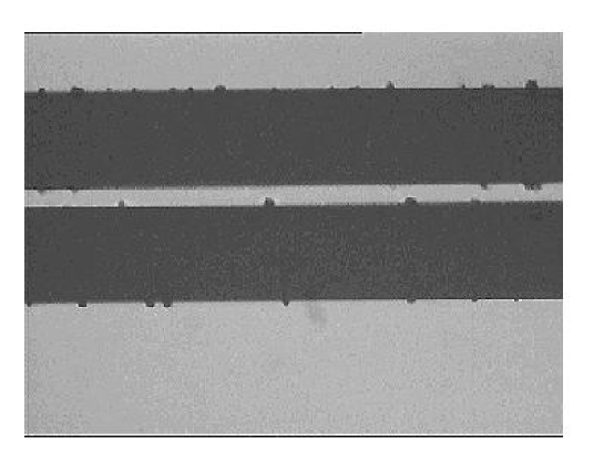
Already the very first day of operation we observed a severe problem which was not encountered in the laboratory. The cathode current showed large spikes, at the same time anodes got lost and sometimes pre-amplifier channels were destroyed. Inspection of the electrode structure in the laboratory under the microscope showed characteristic defects. In the area of the beam spot marks are found on the gold electrodes where the gold is evaporated both from the anode and from the cathode just opposite to each other. A typical photograph is shown in Figure 2. Obviously gas discharges had occurred which sometimes were so intense that they cut an anode strip completely. The lifetime of the chambers in the HERA-B environment with the foreseen technology would have been only months.
Since discharges had never been observed in intense X-ray beams at exposures with much higher charge deposition rate, it was suspected that the origin of the discharges were strongly ionizing particles like nuclear fragments produced in hadronic beams through interaction with detector material.
A series of laboratory tests where large local ionization was created by particles was carried out to study this effect.
2.4 Gas discharges by strongly ionizing particles
The observed sparking phenomena in MSGC and MSGC/GEM detectors have partially been published [9, 10]. Here a summary of the results is given. Systematic measurements are difficult because the sparking process damages the electrodes and thus modifies the operation conditions during a measurement. Repeating measurements with the same detector often is impossible.
In order to get ionization by heavy particles the counting gas was guided through a stainless steel volume filled with thorium powder. Thorium decays into radium which is transported with the gas into the MSGC gas volume where it emits particles. A typical particle counting rate of 10 Hz could be achieved this way. The MSGC detectors were operated at nominal voltages and could also be illuminated in addition with an intense X-ray beam. Gas discharges were detected by detection of large induced signals on the cathodes. Alternatively, direct irradiation with a collimated -source through a thin window was used to measure local effects.
A characteristic result from the second method is presented in Figure 3 which shows the spark rate as a function of the cathode and drift voltages measured with a 0.15 m thick chromium structure and with 1 m thick aluminium electrodes. We observe a strong exponential rise of the spark rate with the cathode voltage which is responsible for the field near the surface and a much weaker dependence on the drift voltage. At fixed gas gain, high drift fields are favorable.
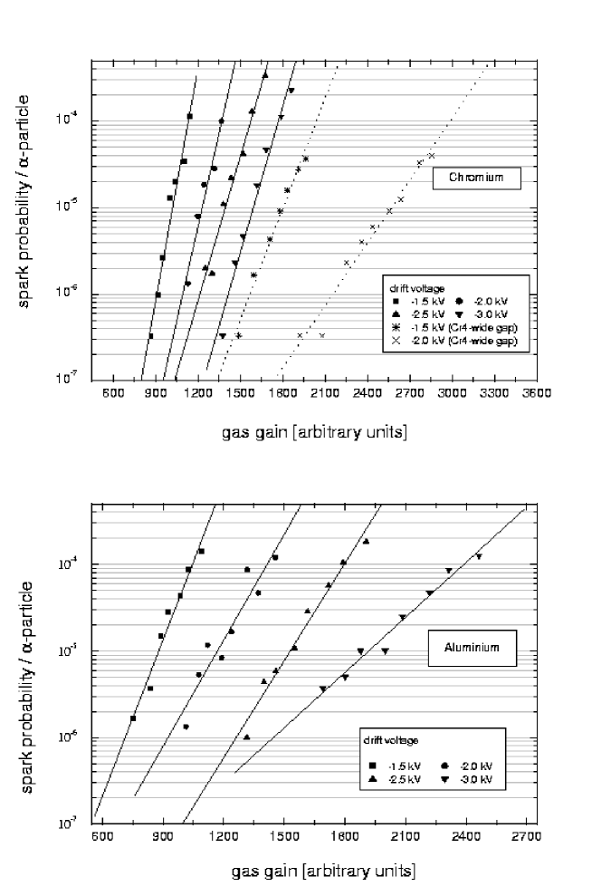
The effect of the width of the anode cathode gap was studied by increasing it by a factor two to 120 m. At fixed gain the spark rate is smaller (see Figure 3), but this positive effect is more than compensated by the more severe damage per spark observed with the wide gap, where the energy stored in the anode-cathode capacitance is much larger.
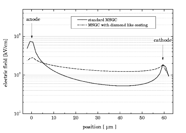
The high sparking rate of the coated MSGCs is explained by the nearly constant electric field component parallel to the surface near the surface, whereas bare glass produces a strongly decreasing field near the anode, which suppresses streamer discharges [11, 12]. The electric fields between the electrodes computed for a coated and an uncoated substrate are shown in Figure 4. Even though dynamical effects from the space charge created by the avalanche are neglected, the simulation illustrates the qualitative difference between the two configurations.
The explanation for the reduced sparking threshold for coated wafers was confirmed by experimental evidence that sparks were predominantly induced by ionization near the surface and is supported by the favorable effect of high drift fields at fixed gas gain.
The spark rate should mainly depend on the electric field configuration and the geometry and be rather independent of the electrode material but we expected a different robustness of various electrode metals against sparking. The hope was that elements with high melting points and high binding energies like rhodium or tungsten would be less vulnerable than gold. However, we did not observe any substantial difference between Au, Cr666Chromium was excluded as a possible electrode material because its resistivity is too high. However, it is well suited for systematic studies of discharges in MSGCs., W and Rh and only a slightly better performance of Al for a given resistivity of the anode [13]. Aluminium electrodes which can be produced with higher thickness than gold or rhodium sustained a somewhat higher number of sparks before they break but this metal is excluded because of its rather bad aging properties. Anodes with high electric resistivity inhibit discharge of the full anode cathode capacitance in a single spark. They show sequential discharges of low charge. The first spark discharges a few centimeters and produces a local potential drop. A subsequent spark occurs after the potential has again reached a critical value. This process repeats itself until the total charge stored in the anode cathode capacitance drops below a certain minimum. This process limits the total energy release in the discharge and explains the fact that chromium structures can survive more than 106 sparks without being destroyed. The sequential discharges are well described by simulations of the electric circuitry [10, 13].
Unfortunately, as explained in Section 2.2, anodes of high electric resistance are incompatible with the requirement of short readout pulses. The geometry of the HERA-B detectors with long strip lengths and the correspondingly high capacitance per channel of 25 pC (including the contribution from the connections) leads to a white noise of the readout of 2250 electrons per channel. Given our amplifier characteristics, a total gas gain exceeding 4000 is required to get good efficiency. With such a gas gain the discharge rate is unacceptably high in intense hadron beams such that MSGC detectors of the HERA-B geometry cannot be operated.
Ne-DME mixtures were reported to have higher primary ionization [14]. However, our tests have shown that the sparking probability at fixed gain cannot be significantly improved within the uncertainties of the measurement of about 20 %.
The sparking problem could only be solved by introducing a gas electron multiplier (GEM) foil [5] as a first amplification step and thereby reducing the gain requirement for the MSGC.
3 MSGC-GEM detectors
3.1 Detector geometry
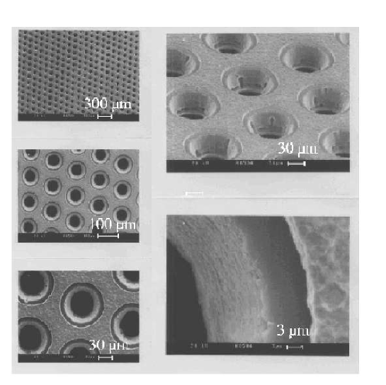
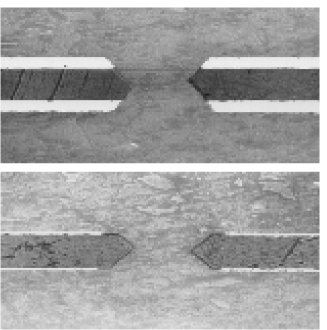
The GEMs used for the ITR were produced at the CERN workshop777CERN Surface Treatment Workshop, Geneva, Switzerland using a wet etching technique. They were made out of 50 m thick polyimide (Kapton) foils coated with a 15 m copper layer on each side. In a final etching step the thickness of the copper layers was reduced to about 7 m. The conical holes have diameters of about 50 m in the Kapton and 100 m in the copper. Photographs of the GEM and of its cross section are shown in Figures 5, 6. The holes are arranged in a hexagonal lattice with a hole distance of 140 m from center to center.
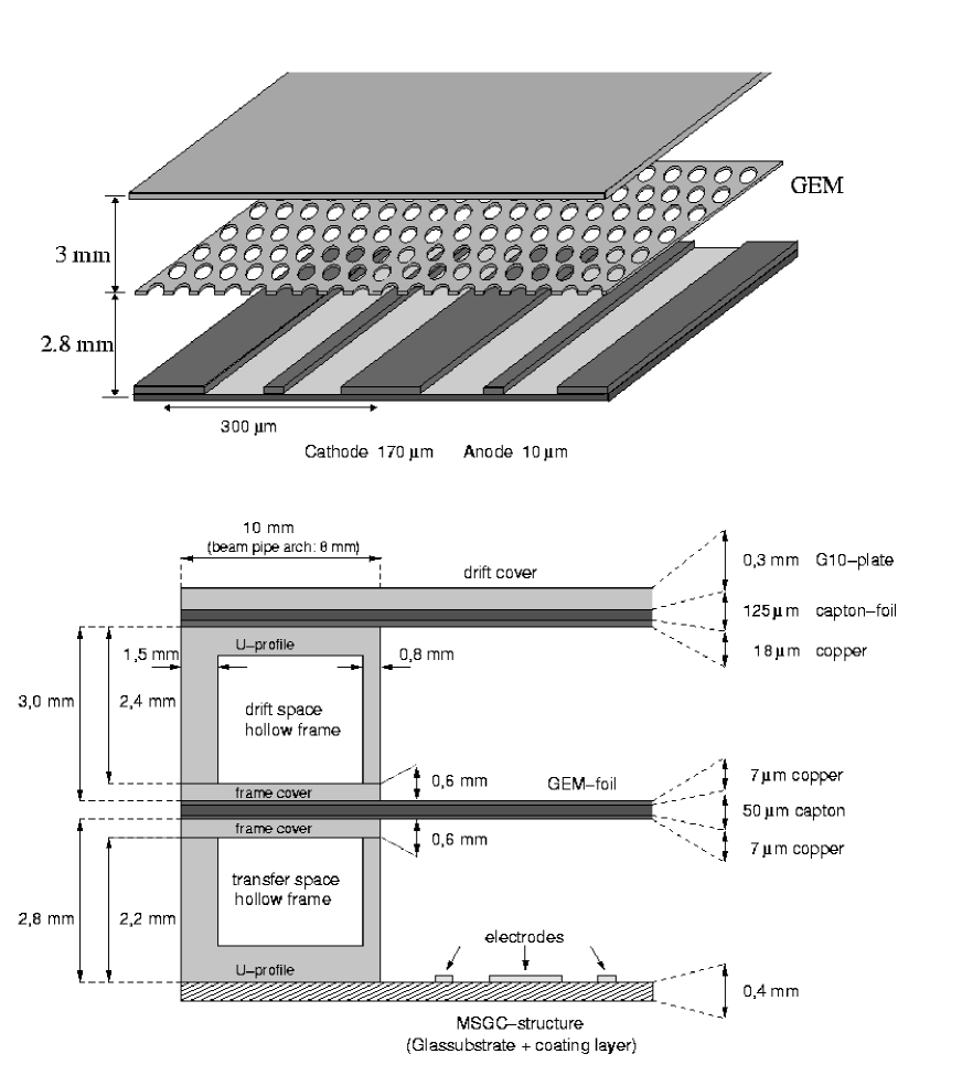
The introduction of the GEM foil required a complete re-design of the chambers. Figure 7 illustrates the construction. The frames which provide the mechanical stability to keep the GEM at constant distance from the MSGC and distribute the gas, consist of two hollow epoxy pieces. The drift gap above the GEM and the transfer gap below are 3.0 mm and 2.8 mm wide, respectively.
The geometrical parameters of the detector are summarized in Table 2.
| MSGC | |
|---|---|
| active area, type A | 528 cm2 |
| active area, type B | 689 cm2 |
| wafer thickness | 400 m |
| anode width | 10 m |
| anode cathode gap | 60 m |
| pitch, type A | 300 m |
| pitch type B | 350 m |
| GEM | |
| GEM thickness | 64 m |
| thickness of GEM electrodes | 7 m |
| hole diameter at center | 50 m |
| hole diameter at electrodes | 100 m |
| Frame | |
| height of drift gap | 3 mm |
| height of transfer gap | 2.8 mm |
3.2 Operation characteristics
Splitting of the gas amplification into two steps allowed to operate the MSGC at moderate voltage. Typical voltage settings during the testing phase were V, V, kV which correspond to gas amplification factors of about 35 for the GEM and 250 for the MSGC. For comparison to reach the same amplification with a single MSGC structure, one would have to apply about 100 V higher cathode voltages. The detectors were tested intensively in the laboratory and at hadron beams at PSI and in the HERA-B experiment.
The GEM shows the characteristic behavior of devices containing dielectric materials. After switching on the HV, the gas amplification of the GEM rises by a factor of about two within a few hours and stabilizes after a few days, when the polyimide is fully polarized. The gain is rather uniform. It varies by less than 20 % over the full area of the chamber. During irradiation the polyimide charges up and the gain increases by up to 20 %. The gain variations with time and rate can be inhibited by coating the GEM foils [15]. Since they are not critical for the operation at HERA we avoided the complication, risk and cost of an additional production step.
With the GEM alone, gas amplification up to 103 could be obtained with photon irradiation before sparking started.
A part of the ITR chambers are located inside the spectrometer magnet with a field of 0.85 T. Initial worries that the GEM functionality would suffer in moderate magnetic fields were not confirmed by a test at the nominal HERA-B field perpendicular to the hole axis. No decrease of the gain was observed within 5 % [18].
3.3 GEM sparks inducing secondary sparks
First laboratory tests at the PSI pion beam in 1998 of four MSGC/GEM chambers operated with Ar-DME 50/50 at a GEM gain of about 50 gave satisfactory results [16]. A second test one year later, however, was similarly disastrous as our first MSGC tests at a hadron beam. GEM sparks were observed which induced secondary sparks at the microstrip structure, and sometimes led to discharges between the GEM and the microstrip structure or between GEM and the drift electrode. The electrodes of the MSGC were severely damaged.
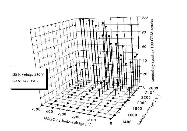
In extensive laboratory studies the secondary sparking was reproduced and investigated. The details of the complex sparking process were never fully understood. However, it is obvious that a discharge of the GEM with its high capacitance generates a huge amount of ions and electrons. Even a small fraction of the electrons drifting towards the MSGC, with additional gas amplification there, are likely to produce secondary sparks. Thus the rate of those strongly depends on the strength of the transfer field. This was confirmed by laboratory measurements presented in Figure 8 and it explained also the different behavior of the chambers at the two PSI tests which were performed at slightly different HV settings.
A significant dependence of the secondary spark rate on the cathode voltage has not been observed (see Figure 8).
With the voltage between anodes and lower GEM plane limited to below 1250 V in the HERA-B experiment, the MSGC/GEM detectors were able to cope with the intense hadron flux without suffering from fatal damage by discharges (see Section 5).
4 Choice of counting gas and aging studies
Two gas mixtures were systematically studied, Ar-DME 50/50 and Ar-CO2 70/30. The DME mixture has better quenching properties hence less problems with gas discharges. It had also been extensively tested with respect to aging properties by several groups, which consistently reported no aging problems up to large charge depositions on the strips corresponding to many years of LHC or HERA-B operation [17]. Compared to Ar-CO2 70/30 it also has larger primary ionization, 24 primary electrons in average for a minimum ionizing particle in the 3 mm gas gap for Ar-DME compared to 18 for Ar-CO2 which has also significantly larger transverse diffusion. However, there are also disadvantages of Ar-DME: The Ar-DME mixture is flammable and constitutes therefore a safety risk. DME is not commercially available with guaranteed purity. Thus every bottle would have to be checked carefully in aging tests to ensure that the detectors are not polluted. In addition, we realized that DME is absorbed by Kapton leading to a reduction of the GEM tension with time. After flushing the chamber for 2 weeks, we observed a sag of a foil by 800 m. The original tension could be recovered by changing the gas [18]. The use of DME would have required additional constructional efforts to keep the GEM foil in place.
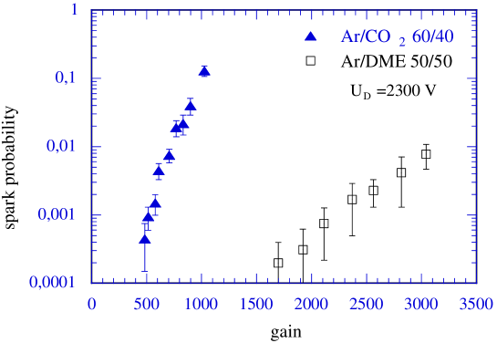
Comparative sparking tests in the laboratory with particles in the gas indeed demonstrated that the spark protection of Ar-CO2 is significantly worse for the same gas gain. This is illustrated in Figure 9 which shows the spark rates for Ar-CO2 and Ar-DME versus gas gain. The result cannot be safely extrapolated to the low operation voltages in a MSGC/GEM detector. It is nevertheless obvious that Ar-CO2 offers less safety with respect to gas discharges than Ar-DME. Protection against sparking can be strongly improved for Ar-CO2 by adding small amounts of water to the gas. However, as discussed below, the addition of water led to fast gas aging and was therefore ruled out for HERA-B.
4.1 Experimental method for gas aging tests
Big efforts have been made by several groups to study gas aging phenomena in MSGCs [2]. These studies are difficult and hard to reproduce because gas aging depends on a multitude of different parameters. It was however clear from the beginning that the MSGC structures are very vulnerable and that even tiny amounts of pollutions by organic materials can cause fatal deposits on the anodes. Therefore, most of the counting gases which have been used in wire chambers involving organic quenchers cannot be used in MSGCs for high rate applications. Moreover, we made a very careful selection of materials like composites, glues and applied elaborated cleaning and outgassing procedures to avoid pollution of the counting gas. The gas system was entirely based on stainless steel tubing. The sealing rings were made of Kalrez888Dupont Dow Elastomers, Belgium., materials like Teflon were avoided. All materials were also tested for out-gassing both using gas chromatography and by exposing large surfaces of them to the input stream of counting gas used in gas aging tests of MSGC detectors.
An X-ray tube with copper anode was used to produce a high flux of photons. The X-rays were collimated by a lead collimator such that a round area of 113 mm2 was irradiated. The detector was operated at a total gas gain of about 3500. The gas flow was arranged such that the gas in the detector was exchanged twice per hour. The typical counting rate was about 100 kHz/cm strip length. One X-ray count led to an average avalanche size of about 840000 and this rate corresponds to a charge deposition rate per cm strip length which is about 20 times higher than that of the hottest region at HERA-B. This acceleration factor was varied between 1 and 40 for different tests but the large integrated charge depositions with illuminations over several months used acceleration factors of not more than 20. The position of the Cu line was evaluated in regular intervals during these measurements to track possible changes in the gas gain.
Aging tests were carried out with a large number of detectors over a period of three years. With the full size HERA-B MSGC/GEM pre-series detectors we observed neither for Ar-DME nor for Ar-CO2 any significant change of the pulse height up to an integrated charge of 45 mC/cm which corresponds to about 6 years of HERA-B operation. This result was supported by optical inspection of the irradiated areas which showed no sign of depositions on the anodes. This result was interpreted as sufficient reassurance for our choice of counting gas and constructional materials to start mass production of the detectors in spring 1998. It should be noted that our result was in line with similar measurements of other groups [17]. All their results were obtained with small irradiated areas of sometimes only 7 mm2.
4.2 Observation of gas aging for Ar-DME mixtures
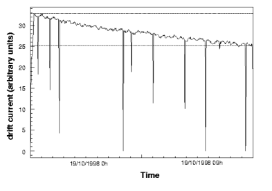
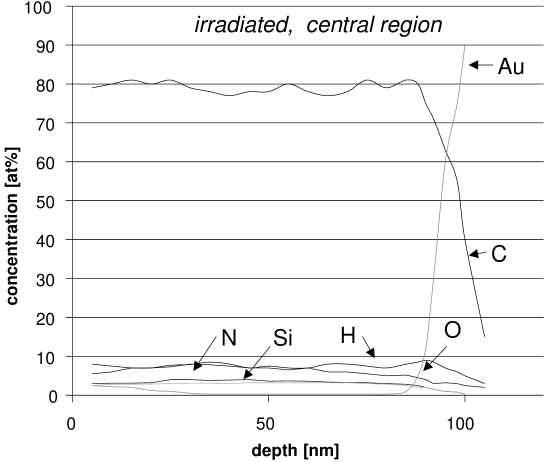
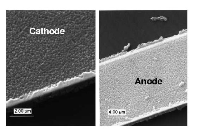
In autumn 1998 a beam test was carried out at PSI with two full size MSGC/GEM detectors using Ar-DME 50/50 as counting gas. The goal was twofold: during daytime the pion beam was used to study efficiencies, resolution and the performance of our trigger chain. During night time the detectors were exposed to an intense proton beam to accumulate a higher charge dose. The beam spot had a Gaussian profile with a typical full width at half maximum of 5 cm. Within few days a total accumulated charge of 2 mC/cm was reached in the center region. We observed a rather fast reduction of the drift current during proton irradiation for constant beam current. This was even seen online as shown in Figure 10 for a 12 hour period of proton running at maximal intensity (about 20 times HERA-B charge deposition rate). The detectors were subsequently investigated in the laboratory. Within the illuminated area the detectors still showed acceptable gas gain but outside the illuminated area they did not count at all. Optical inspection showed severe deposits on those anodes which were connected to ground and therefore experienced the nominal electrical field. Disconnected anodes showed no deposits. Depositions were found both in the irradiated area and over the rest of the detector. Parts of an irradiated wafer were sent to the Fraunhofer Institut für Schicht- und Oberflächentechnik which carried out a surface analysis shown in Figure 11. The anodes in the irradiated area were covered by a layer of 80 nm pure carbon. A picture of these deposits as seen with an electron microscope is shown in Figure 12. The areas outside, which were not irradiated were covered by an insulating layer of about 35 nm composed of hydrogen and carbon.
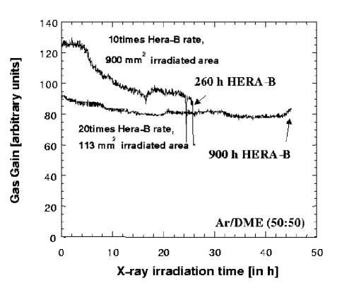
This unexpected result prompted a series of new laboratory aging tests. The final outcome is very surprising. The Ar-DME gas mixture shows gas aging under X-ray irradiation if the area which is irradiated is large enough. This fact is illustrated in Figure 13 which shows the gas gain versus irradiation time for a collimator with an area of 113 mm2 as used before compared to one with an area of 900 mm2. The large area was irradiated at half the local intensity of the smaller one. Identical chambers operated with Ar-CO2 show no aging independent of the size of the irradiation area.
Apparently, irradiation of a large area with Ar-DME as a counting gas leads to fast aging and visible deposits on the anodes. These deposits are not limited to the irradiated area. We therefore have to draw the conclusion that gas aging effects depend strongly on the size of the irradiated area. All evidence supports the assumption that the origin of these deposits is the DME itself. We have no explanation for this experimental fact but it invalidates all aging tests done before.
Subsequently Ar-CO2 was chosen as the main candidate for the counting gas.
As this gas mixture has low primary ionization and large transverse electron diffusion leading to large cluster width in the detector, we tested several other gas mixtures without hydrocarbons. These were Ne-CO2, Kr-CO2 and He-CO2 mixtures. The results were unfortunately discouraging. Measurements with MSGCs showed that for the same avalanche charge on the anodes these gases led to comparable cluster widths but poorer performance with respect to discharge protection. We therefore chose the Ar-CO2 70/30 gas mixture.
4.3 Aging results for different materials and counting gases
As explained in Section 3, the safety against gas discharges became a major concern. We therefore tested different combinations of electrode materials and counting gases which promised better protection.
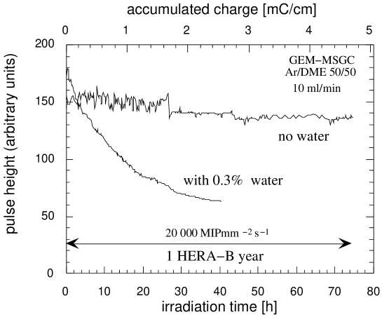
The operation characteristics of a MSGC can be significantly improved by adding small amounts of water, typically 0.3%, to the counting gas. This avoids discharges near insulators e.g. near the detector frames and anode ends and improves the overall protection against sparking, probably by reducing the surface resistivity of plastic materials which tend to absorb water. Addition of water to the counting gas shows however very severe and fast gas aging for both, Ar-DME and Ar-CO2. This is shown in Figure 14 which compares the pulse height as a function of accumulated charge for Ar-DME with and without an admixture of water. For the gas with water admixture the pulse height drops by a factor three for an accumulated charge of less than 3 mC/cm. Moreover the anodes show deposits in the irradiated area.
We also tested MSGCs with aluminium electrodes. Aluminium electrodes are easier to manufacture and sparking tests showed that the electrodes are more robust against discharges than gold but aluminium is known to introduce aging in MSGCs [19]. Our aging tests with aluminium MSGC/GEM detectors confirmed that this material cannot be used with Ar-DME or with Ar-CO2. In both cases we observed a fast reduction of the pulse height by more than 20% for an accumulated charge of only 2.7 mC/cm. Moreover, the electrodes were severely damaged. Especially the cathodes showed bubbles and craters in the irradiated area.

A rather interesting phenomenon was observed for very long irradiation times for chambers operated with gas mixtures without indication for gas aging like Ar-CO2 and Ar-CO2-CF4 which is used in the Outer Tracker of HERA-B. After a stable period corresponding to about one HERA-B year these chambers show a strong increase of pulse height with time of up to a factor four. For some intermediate time the gas gain becomes very inhomogeneous, changing locally by more than a factor two. After an exposure corresponding to about five years of HERA-B operation the gain becomes stable again but is about four times higher than at the beginning. The gain in this state depends strongly on the counting rate which indicates that the surface near the anodes has become insulating such that charging-up affects the gain. The origin of these effects was clarified by a detailed surface analysis. The intense plasma which is created during the aging tests destroys the DLC layer near the anodes. It is gradually etched away up to the point that there is an insulating strip near the anode edges. This is illustrated in Figure 15 which shows the measured thickness of the coating as a function of the distance between anode and cathode for an area where a charge of 40 mC/cm was accumulated. The coating is etched away almost completely near the anode and is reduced over the whole gap compared to the starting thickness of about 80 nm. With Ar-CO2 this effect is relatively slow under the conditions of our aging tests, for a gas mixture including CF4 the effect is much faster such that the coating would be destroyed completely for a collected charge of only 2 mC/cm. This gas can therefore not be used. The observed etching effect is of course likely to depend strongly on the local current and plasma density and could be very different for the running conditions of the HERA-B experiment. It is therefore impossible to predict if and how fast such a change would appear at HERA-B. The final beam test at PSI in 1999 using low energy protons was used to accumulate a deposited charge equivalent to 1/3 year of HERA-B operation. During this relatively small exposure no signs of gas aging or damage of the DLC were observed.
5 Operation at HERA-B
5.1 Treatment of the detector components before installation
During production, the different parts of the ITR went through several tests:
The wafers were checked at Zurich directly after production (see Section 2.2). Interrupted anodes were recorded.
All GEMs were tested in Heidelberg before chamber construction. The GEMs had to sustain 500 V in a nitrogen atmosphere for 12 hours.
The individual chambers were transported to Siegen for bonding of the electronics. At Siegen they were flushed with the final chamber gas and put to high voltage. Within a period of 24 hours the voltages were ramped up to 520 V for the cathode and to 410 V across the GEM. All currents were recorded and put into a reference file. About half of the chambers showed anode cathode shorts. These shorts were eliminated by disconnecting the anode. In 10 chambers fatal GEM shorts were observed.
Chambers fulfilling the requirements went back to Heidelberg. There the stations were put together and fully assembled stations were shipped to DESY. Before installation another high voltage test similar to the one at Siegen was performed. The required voltages were 490 V for the cathodes and 400 V across the GEMs. In 12 out of 144 tested chambers an anode cathode short was detected. One chamber showed a GEM short.
Apparently, each construction or transportation step introduced some damage to part of the detectors and the intermediate high voltage tests could not exclude additional problems occurring later in the hadron beam of HERA-B.
5.2 Operation conditions and observed problems
During the period from July 1999 to May 2000 a total of 150 chambers were installed and operated at HERA-B. The first few months of the year 2000 were mainly devoted to commissioning of the detectors. Data were routinely taken from April to the end of the running period by August 2000. The maximum operation time of 1100 hours was reached by 56 chambers. During the last two months 90 % of the installed chambers were routinely participating in data taking without major problems.
The interaction rate at the target varied between 3 MHz and 40 MHz. Most of the data were taken at 5 MHz. A typical distribution of the hit density in a detector is shown in Figure 16 for 5 MHz interaction rate. The hit density is about 0.006 per anode and event. The shape of the distribution is determined by the beam recess of the MSGC wafer (see Fig. 1) and the radial decrease of particle density.

The raw pulse height distribution cannot be used to determine the gas gain because it is dominated by soft signals which do not belong to tracks. We therefore need to reconstruct tracks first to measure a signal over noise distribution and the efficiency. Since at the beginning of the run the track reconstruction program was not yet well tuned, it was possible only for the chambers in front of the magnet to estimate during running the efficiencies which have to be known in order to adjust the high voltage. Typical voltage settings were -510 V for the cathode and 420 to 450 V for the GEM. Individual GEM voltage settings were necessary to correct for the gain variations of up to a factor 2.5 from GEM to GEM which are caused by slight alignment imperfections of the copper holes at the two sides of the GEM. The high voltage settings for the remaining chambers could not be adjusted and therefore the chambers were operated at GEM voltages below 440 V and correspondingly more moderate gain.
While at the end of the data taking period running was rather smooth, several problems occurred after installation:
-
•
Four GEMs developed conductive paths between their two copper surfaces. The resistivity dropped to values of the order of M, values which effectively short the two GEM electrodes.
-
•
In 43 % of the chambers the MSGC electrodes showed one or two short circuits between anode and cathode strips.
These problems occurred shortly after installation and were probably due to spurious dust or production defects.
5.2.1 GEM sparks
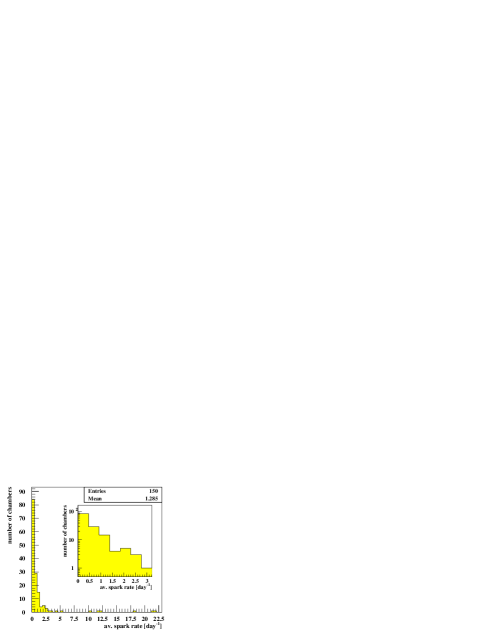
Sparking in GEMs cannot be avoided completely, but under normal conditions the rate is quite low, of the order of a single spark per day (see Figure 17), a rate which is tolerable. Only six chambers showed sparking at rates above ten per day.
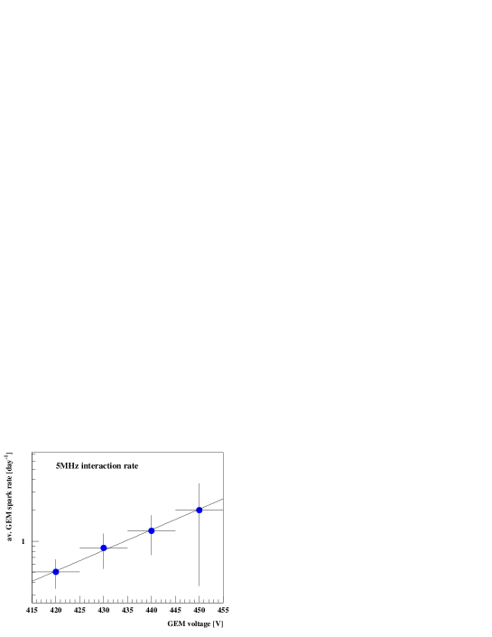
The spark rate increases exponentially with the GEM voltage rising from 1 to 5 sparks/day when the GEM voltage is increased from 400 V to 450 V. This is shown in Figure 18 for chambers behaving normally. Chambers with exceptional high rates are excluded in this Figure to avoid a biased picture. As expected, the sparking rates increased with the beam intensity. Similar results have been reported in Refs. [20, 21] where a linear dependence of the sparking probability on the beam intensity and a strong dependence on the beam composition has been observed.
While under normal conditions the spurious sparking does not disturb the performance of the detectors, in some cases continuous sparking produced GEM “shorts” by carbonizing the polyimide surface in the hole.
In some cases when the resulting conductivity across the GEM was low, the “short” could be burned away by applying a short current pulse which evaporates the copper near the affected hole. When this was not possible, the whole chamber was lost.
At one occasion, the damage of a GEM could be correlated to a spike in the target rate.
5.2.2 Anode cathode shorts
A total of 79 anode cathode shorts were observed during the run period in 2000. Due to the HV grouping of the cathodes this corresponds to a loss of 1.1% of all anode strips. Out of the total, 29 shorts were produced already within the first 10 hours after switching on and only 16 occurred in the second half of the running period. Most of the late shorts coincided with an increase in the high voltage.
Inspection of the chambers during the HERA luminosity upgrade shut-down revealed that some shorts are correlated to anodes with lithographic defects. Interrupted anodes show a tenfold higher probability to produce a short than perfect anodes. Interrupted anodes have now been disconnected electrically from ground to avoid this problem. The corresponding loss in efficiency is completely negligible.
5.2.3 Consequences
Most problems occurred at the beginning of the operation in the beam. They can be avoided or at least reduced to a tolerable level by the following measures:
-
•
operating the detectors for some days at overvoltage before installation,
-
•
carefully training the chambers in the HERA-B beam before applying the full high voltage,
-
•
HV control based on monitoring of the currents and on spark detection,
-
•
applying a coordinated ramping of the different chamber high voltages,
-
•
avoiding unstable beam conditions.
During the 2000 running period a training procedure has been worked out which has led to a considerable improvement of the reliability of the detectors. The voltages are raised slowly in ten steps over a period of two to four weeks (400 hours beam time) depending on the chamber behavior. Very few problems were observed with chambers treated in this way.
A control system based on microprocessors inside the high voltage distribution boxes has been optimized. It continuously monitors the drift and cathode currents and the GEM voltages. In addition, it detects sparking through rapid voltage changes. When a spark occurs, the voltages are decreased thereby avoiding sequential sparks. After some delay, the voltages are automatically ramped up again. The behavior of all chambers is continuously monitored online.
Meanwhile all damaged chambers have been exchanged. Cathode groups have been re-activated by cutting the anode responsible for the short. Extrapolation from the experience gained last year indicates that we should be able to operate the ITR with less than 1% of channels lost per year.
5.3 Performance
The detectors show a noise distribution with a mean value of 2500 electrons. This value is well compatible with the estimate from the strip capacitance and the amplifier input resistor value. A signal over noise (S/N) plot is shown in Figure 19.

Efficiencies of the chambers in front of the magnet could be determined during running using well reconstructed tracks extrapolated from the vertex detector. They are presented in Figure 20 as a function of the GEM voltage. The efficiencies are above 90 % which is sufficient for tracking.

As mentioned above, there are considerable variations in the GEM performance from chamber to chamber which are compensated by adjusting the GEM high voltage which can be individually set for each chamber. The local gain variations across a single chamber, however, are quite small, namely below 10 %.
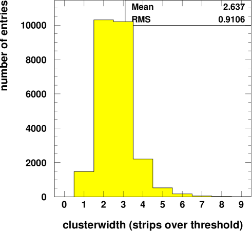
The strip multiplicity distribution shown in Figure 21 corresponds to a mean value of 2.6 for a threshold of 5000 electrons, which is twice the average noise level. This rather high value is compatible with the large transverse diffusion in Ar-CO2 along the long drift path of the electrons.
The ITR chambers have been geometrically aligned using an iterative fitting method. A residual distribution for fitted tracks of particles with momenta between 35 and 50 GeV/c is presented in Figure 22. In average 15 chambers contribute to one track. From a comparison of the observed root mean error of 105 m with a Monte Carlo simulation we conclude that the intrinsic spatial resolution of the detectors is better than 110 m.

6 Conclusions
After many unexpected difficulties the development of the ITR for HERA-B has led to a detector which is working to the required specifications. Efficiencies greater than 90% were achieved for part of the chambers and are expected for the full detector during the next running period. Extrapolation of the present experience indicates that inefficiencies due to anode cathode shorts will remain below the 1% level.
Irradiation with X-rays have revealed that aging for Ar-DME gas mixtures depend strongly on the size of the irradiated area. Measurements with Ar-CO2, 70/30 did not show the same behavior and indicate that our detectors would adequately perform for more than six HERA-B years. Irradiation also affects the DLC which is etched away starting from the anode borders. This leads to gain variations with time and beam intensity.
The MSGC with the dimensions necessary at HERA-B and the beam conditions of HERA cannot be operated reliably without the addition of a GEM. At the gas amplification required to obtain sufficient efficiency the spark rates would be lethal. The situation here is different from that at LHC where with much smaller detectors simpler solutions would have been possible [22]. Our system is quite fragile and expensive and requires a complicated HV steering. With the knowledge gained in the last few years, it has become clear that new, more robust devices like multi GEM detectors [23, 20, 24] are better suited for harsh beam environments than MSGC based systems.
Acknowledgment
We acknowledge the strong effort of the technical stuff of the collaborating institutions. In particular, we wish to thank S. Henneberger, R. Rusniak, A. Rausch, Ch. Rummel, D. Gieser, R. Eitel and S. Rabenecker (Heidelberg), O. Meyer, G. Schmidt (Siegen), K. Boesiger, K. Esslinger, B. Schmid and S. Steiner (Zuerich), Serguei Cheviakhov (DESY). Our work profited very much from the close collaboration with the vertex detector group of the MPI Heidelberg, especially in the areas of readout and monitoring.
References
- [1] T. Lohse et al., ”An Experiment to Study CP Violation in the B System Using an Internal Target at the HERA Proton Ring”, DESY-PRC 94/02 (1994).
- [2] F. Sauli et al., ”Development of Micro-Strip Gas Chambers for Radiation Detection and Tracking at High Rates”, Status report, CERN/DRDC/93-34, (1993).
- [3] F. Sauli et al., ”Development of Micro-Strip Gas Chambers for Radiation Detection and Tracking at High Rates”, Status report, CERN/DRDC/94-45 (1995).
- [4] CMS-Collaboration, ”Status report and milestones”, CERN/LHCC 94-20 (1994).
- [5] F. Sauli, ”GEM: A new concept for electron gas amplification in gas detectors”, Nucl. Instr. Meth. A 386 (1997) 531.
- [6] S. B. Visbeck, ”Untersuchungen von Prototypen der Mikrostreifen Gaskammern (MSGC) des inneren Spurkammersystems des HERA-B Experiments”, diploma thesis, Heidelberg (1996).
- [7] E. Ermert et al., ”Study of electric properties of microstrip gas counters with and without coating”, in Proc. 3rd Int. Workshop on Micro-Strip Gas Chambers, Lyon, 1995.
- [8] Thomas M. Walter, ”Contributions to the Development of Microstrip Gas Chambers (MSGC) for the HERA-B Experiment”, Ph.D. thesis, Universität Zürich 2001.
- [9] B. Schmidt, ”Microstrip gas chambers: Recent developments, radiation damage and long-term behavior”, Nucl. Instr. Meth. A 419 (1998) 230.
- [10] S. Keller et al.,”Sparks in MSGCs”, Nucl. Instr. Meth. A 419 (1998) 382.
- [11] V. Peskov et al., ”Feedback and breakdown in microstrip gas counters”, Nucl. Instr. Meth. A 392 (1997) 89.
- [12] A. Bressan et al., ”High rate behavior and discharge limits in micro-pattern detectors”, Nucl. Instr. Meth. A 424 (1999) 321.
- [13] S. Keller, ”Funkenüberschläge in Mikrostreifengasdetektoren”, diploma thesis Siegen (1998).
- [14] G. Bayatian et al., ”The Tracker Project”, CMS TDR 5, CERN/LHCC 98-6 (1998).
- [15] S. Beirle et al., ”Carbon coated gas electron multipliers”, Nucl. Instr. Meth. A 423 (1999) 297.
- [16] H.-B. Dreis et al., ”Operation of a large GEM-MSGC detector in a high intensity hadronic test beam using fully pipelined readout electronics”, LHCb note TRAC-98/060.
- [17] R. Bouclier et al., ”Performance of Gas Microstrip Chambers on Glass Substrates with Electronic Conductivity”, Nucl. Instr. Meth. A 332 (1993) 100.
- [18] M. Hildebrandt, ”Entwicklung und Bau der Detektoren für das Innere Spurkammersystem bei HERA-B”, Ph.D. thesis, Heidelberg (1999).
- [19] Bateman et al., ”The Experimental Characterisation of Gas Microstrip Detectors, III Lifetime Characteristics”, RAL Report, RAL-94-114 (1994). Bateman et al., ”Rate and lifetime characteristics of a gas microstrip detector fabricated on sputtered S8900 glass”, RAL-TR-95-032 (1995).
- [20] M. Ziegler et al., ”A triple GEM detector with two-dimensional readout”, Nucl. Instr. Meth. A 471 (2000) 260.
- [21] S. Bachmann et al., ”Performance of GEM detectors in high intensity particle beams”, Nucl. Instr. Meth. A 470 (2001) 561.
- [22] V. Zhukov for CMS Collaboration, ”Large scale test of MSGC + GEM detectors in a high intensive hadron beam”, Nucl. Instr. Meth. A 461 (2001) 118.
- [23] Bachmann et al., ”Charge amplification and transfer processes in the gas electron multiplier”, Nucl. Instr. Meth. A 438 (1999) 376.
- [24] B. Ketzer et al., ”GEM detectors for Compass”, IEEE Nucl. Sci. Trans. NS-48 (2001) 1065.