WEDT002 THE KLOE/DANE STATUS LOGGING, ANALYSIS AND DATABASE SYSTEM
Abstract
The KLOE experiment [1] at the Frascati -factory DANE [2], designed to measure , began preliminary data taking in the Fall of 1999. A large database structure, which logs information coming from the DANE control system and the KLOE slow control and data acquisition systems, has been developed. Data from detector monitoring, online event processing and machine operating conditions are easily accessible for online and offline analysis by means of Web tools and histogramming tools. The system allows powerful real-time data correlations which are necessary for the ongoing program of luminosity and background improvements. Data flow and handling processes are presented.
1 DANE control system
Data in the DANE collider are stored by the control system [3] in the local memories of the 45 front-end VME-CPU’s distributed all over the accelerator area. The front-end tasks get commands from the high-level user environment and continually update their own database with information from the devices. Data are available through direct memory access to the CPU’s memory. This front-end database is constituted by different data types tailored to specific machine elements (non-homogenous database); this means that in order to use this data or to correlate parameters of different devices, specific routines must be implemented.
Two system tasks have been developed in order to collect all the parameters (Dumper), to synchronize and align them, and then to store them to disk (Storer) [4]. The Dumper continuously fetches data from the front-end memories and writes the different data-types from each machine element aligning them in a homogenous database. This memory resident database is accessible from high-level tasks: {Itemize}
for monitoring purposes, such as the watchdog process checking for faulty magnets, bad vacuum or CPU failures;
for the user interface display (from any operator console);
for online correlation and analysis (as described in Sect. 3). The Storer then synchronizes the memory database and writes it on the mass storage at given time intervals.
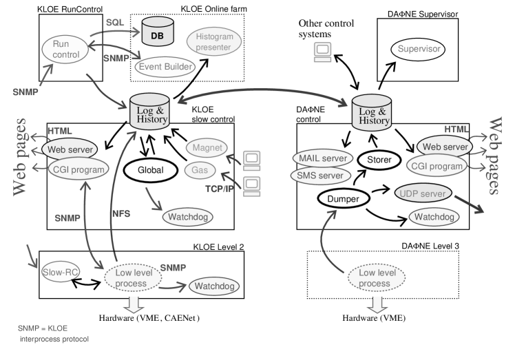
In addition, the Dumper continously reads the status of the satellite systems not belonging to the control system environment (such as the spectrum analyzer), merging this data in the homogenous database. In the general scheme of DANE controls, sketched in the right part of Fig. 1, the main processes and data flow are reported. In addition to the control and monitoring functions, and the communication with the KLOE slow control, an additional process serves DANE data to the controls of the synchrotron radiation facility through the UDP protocol (UDP server). The handling of data relative to the DEAR experiment (running at the second interaction region) is not shown in the figure, since it is monitored as any other part of the machine and the data can be presented through the DANE interface.
2 KLOE slow control
The KLOE slow control system [5] is intended not only for the control and monitoring of the low and high voltages used for the detector (more than 70 DAQ crates, 24 HV crates), but also for the monitoring of the trigger and background rates. The hardware is entirely based on the VME standard. Several VME serial interface boards control the HV and LV settings and the power supplies through low-level processes running on a standard KLOE level-2 VME CPU.
Different low-level processes (one for each part of the detector) implement the low-level VME functions. All the data coming from the monitoring are stored to memory and are handled by high-level processes running on a remote machine, which also runs the processes providing the user interface, generating and handling alarm conditions and communicating with satellite systems. The drift chamber gas control and the superconducting magnet system are also monitored by dedicated high level processes, communicating on TCP/IP sockets with the remote controls. Finally, the high-level also communicates with the KLOE run control, both for the logging of the relevant detector parameters, and for the setting of HV and LV at run start.
The user interface is entirely realized using HTML language, so that the monitoring and control functions are implemented by CGI (Common Gateway Interface) programs running on a dedicated Web server, which also displays the anomalous conditions and handles the alarms. The alarm conditions are generated by two different watchdog processes: one running on the low-level VME CPU and accessing the shared memories of the control processes of the subdetectors (via SNMP, the KLOE inter-process communication protocol [6]); the other checking the high-level programs on the main machine, and sending the main alarm conditions via the GSM short message service and e-mail.
All the slow control processes write the monitor parameters to a general ’run condition’ mass storage. The same area is used by DAQ monitoring processes, running on the KLOE online farm, which perform a fast event reconstruction of acquired data [6]. These monitoring processes produce the relevant quantities from online analysis, such as luminosity, beam position, and background level.
The general scheme of the KLOE controls, with the interactions of the different low and high-level processes, occupies the left part of Fig. 1.
3 KLOE/DANE communication and data integration
The DANE and KLOE mass storages, shared between the two control systems, are used by many monitoring processes to log a number of parameters, in general at very different time intervals: 3 seconds for the scalers counting the hits in the endcap and quadrupole calorimeters, 15 seconds for ’fast’ variables such as current and roundness of the beams, or the status of the low and high voltages, 1 minute for the ’slow’ variables such as the KLOE magnetic field, 5 minutes for the machine vacuum and orbit; or even at non-constant time intervals for the physics quantities, such as luminosity and beam position and momentum measurements, needing some data to be acquired and analysed by the DAQ monitoring processes.
Thus two collaborating tasks, continously running on the two main machines, merge the information coming from the various parts of the two systems and synchronize them: {Itemize}
the Dumper/Storer on the DANE high-level machine, reading and aligning the non-homogenous data from the distributed VME memories and writing them to the DANE homogenous database;
the Global collector process (see Fig. 1) on the KLOE slow control machine, reading data from the shared memories of low-level processes (via the SNMP inter-process protocol), stored data from the high-level processes monitoring satellite systems, and the physics quantities from the online event reconstruction. Some elaboration is also performed starting from low-level data, producing background estimators from spurious hits in the detector, beam lifetimes from the fit of the history of the machine currents, etc.
Finally, the common global database is produced, in which all machine parameters are correlated with the detector quantities. Since there is a wide range of time variations of monitored parameters and of logging time intervals from the various processes (producing or retrieving data), all the available quantities in the final common database are synchronized and stored either in a ’fast file’ (at 15 seconds intervals) or in a ’slow file’ (at 1 minute intervals).
The global database is then accessed by both the DANE and KLOE controls Web servers to display a rich wealth of information: {Itemize}
as already described in the previous sections, the online status;
the long-term history of the machine and detector conditions;
a number of statistics of the most relevant quantities. A number of pages displaying the status and the history of the various parameters and their correlations are made available and extensively used in both control rooms: mostly oriented to the luminosity/machine background optimization in the DANE case, and to keep under control the detector performance and the data quality for KLOE.
In order to help the two teams of physicists in the continous improvement and optimization of the machine/detector operation, the presentation of the monitored quantities and of their correlations is fundamental. This has been realized with two complementary tools taking advantage of the common database: a general-purpose Web interface, running on the DANE Web server, mainly oriented to the display of correlations between different machine and detector quantities, and a histogramming application based on the ROOT libraries (from the CERN program library), running on the KLOE online machines [7], mainly oriented to the presentation of the time charts of any machine or detector parameter. Both the presenting tools access the common database described above, and can display the last few hours status or build the history on a many days base.
An asynchronous builder process continously runs on the DANE supervisor machine, reading the common global database: on the basis of the stored parameters a number of statistics of the machine and detector performance are elaborated, such as delivered luminosity, beam lifetimes, data-taking efficiency, etc. The last-hours, daily or longer term statistics of the most relevant indicators are then made available through the Web interface.
As described above, the supervisor machine also runs a watchdog process checking the most relevant parameters and alarm conditions. A dedicated server takes care of signalling anomalous conditions through the e-mail and GSM short message service, and in addition the daily statistics can be broadcast to the authorized personnel. This can be done in push/pull mode: the operators of the two teams can get the desired information on-demand, or wait for the regular updates.
For safety reasons the KLOE slow control also implements an independent watchdog process, signalling the detector experts the main alarm conditions via e-mail and GSM short messages.
4 Conclusions
The DANE and KLOE control systems manage and monitor the machine and detector elements through a set of low-level programs. The high-levels of the two systems are strongly connected and integrated: the information coming at different times from the detector and machine controls, from the external control systems, and from the online event reconstruction on the KLOE farm are collected, synchronized, stored, pre-analyzed and displayed from a number of tools, based on a common general database accessed mainly by the two supervisor Web sites and by dedicated programs. Duplication is very limited, since the same low-level parameters are elaborated and shown with different approaches, oriented either to machine optimization, or to detector stability and data quality control.
5 Acknowledgments
We are grateful to M. Masciarelli for the work on the DANE side, to A. Balla and G. Corradi for the work on the KLOE side of the control system.
References
- [1] F. Bossi for the KLOE Collaboration, “KLOE Results”, XX International Symposium on Lepton and Photon Interactions at High Energies, Rome, Italy (2001).
- [2] M. Preger for the DANE Team, “Status of DANE”, HEACC 2001, Tsukuba, Japan (2001).
- [3] G. Di Pirro, G. Mazzitelli, I. Sfiligoi, A. Stecchi, “The Evolution of the DANE Control System: A History of Liberation from Hardware”, ICALEPCS 2001, San Jose (CA), USA (2001).
- [4] G. Di Pirro, G. Mazzitelli, A. Stecchi, “Data Handling Tools at DANE”, EPAC 2000, Wien, Austria (2000), LNF-00/021 (P).
- [5] A. Mastrogiacomo, F. Murtas, P. Valente, “The KLOE Slow Control System”, KLOE memo 206 (unpublished), 2000.
- [6] M. Adinolfi et al., “The KLOE DAQ system”, Submitted to Nucl. Instrum. Meth. A.
- [7] M. Martemianov, F. Murtas, P. Valente, “The KLOE Online Presenter”, KLOE memo 236 (unpublished), 2001.