Application of Bent Crystals At IHEP 70-GeV Accelerator To Enhance The Efficiency Of Its Usage
Abstract
Bent crystal was extracting 70-GeV protons with average intensity 41011 (as measured in external beamline) per spill of 1.6 s duration, in parallel to the simultaneous work of two internal targets in the accelerator ring. An additional crystal, placed in the external beamline, was deflecting a small part of the extracted beam with intensity 107 protons toward another physics experiment. Crystal-extracted beam had a typical size of 4 mm by 4 mm fwhm at the end of the external beamline. Measurements for the extraction efficiency and other characteristics at the simultaneous work of four experimental set-ups are presented. With crystal working in the above-said regime during one month, no degradation of channeling was observed. The studies of extraction efficiency have been continued with new crystals.
1 Studies of beam extraction by means of bent crystal
Since 1997 at the IHEP 70 GeV accelerator we carried out studies of proton beam extraction by means of bent silicon crystals [1-4]. These studies pursued the realization of a pure multiturn extraction using short, 5 to 3 mm, O-shaped crystals (see Fig. 1) with small bendings of 2 to 0.5 mrad. Such a small bending of a crystal is insufficient for direct extraction of the beam out of accelerator. Therefore, crystals served as primary element in the existing scheme of slow extraction.

Crystals with bendings of 1.5 to 2 mrad were installed in straight section 19 of the accelerator before the septum-magnet OM-20 of the slow extraction system and provided a kick of the deflected beam into the aperture of this magnet with partition thickness of 8 mm (Fig. 1).
Another series of crystals with bendings of 0.5-1 mrad were installed in straight section 106 (not shown in Fig. 1); here the extraction of the crystal-deflected beam was performed through the septum-magnet OM-24 with partition thickness 2.5 mm (Fig. 1, curve 2).
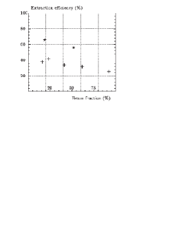
To direct the accelerated beam onto the crystals, the local orbit distortion systems were used working in the regime of close loop operation. The obtained efficiencies are plotted in Fig. 2. The accuracy of the beam extraction efficiency measurements was about 4%. For 20% of the accelerator beam intensity dumped onto the crystal, the measured extraction efficencies were 42% for the 5-mm crystal with 1.5 mrad bending and 65% for the 3-mm crystal with 0.9 mrad bending, installed in straight sections 19 and 106 respectively. The reduction of extraction efficency with increase of the beam fraction dumped onto the crystal is due to the drift of the beam angle at a crystal because of the tilted phase ellipse. During the studies of the extraction efficiency, for a short period of time (1 hour) the regimes of beam extraction of intensity 1.2 protons per cycle were exploited.
2 Example of practical usage of bent crystals at IHEP accelerator
The obtained high efficiencies of the beam extraction with use of bent crystals open new ways for setting up new physical experiments at accelerators. As an example, let us consider one of the schemes for the practical usage of bent crystals realized at U-70 accelerator and shown in Fig. 3.
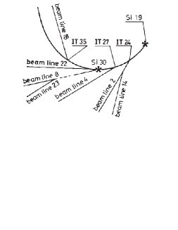
By means of 1.5 mrad bent crystal Si19 (straight section 19) the proton beam of up to 41011 p/cycle intensity was extracted into beamline 8 and directed into beamline 23 onto the target of the experimental set-up used for the studies of -mesons decay modes into three -mesons: . As the -meson yield is about 20 times higher than that of , with the transfer from to the intensity of the extracted proton beam had to be reduced by the same factor. This procedure was repeated regularly with 24 hours period.
Along the path of the extracted beam, at the beginning of beamline 8 another crystal Si30 bent 9 mrad was positioned to deflect a small fraction of the beam (up to 107 protons per cycle) into beamline 22. Simultaneously with crystals Si19 and Si30, two internal targets IT24 and IT27 were working, supplying negatively-charged beams of up to 107 particles/cycle intensity into beamlines 2 and 4 respectively. Besides the physical studies on these four beamlines (22, 23, 4, and 2), methodical work was feasible on the test beamline 18.
To direct the accelerated beam onto crystal Si19 and two internal targets IT24 and IT27 along the flattop of magnet cycle 1.6 s long, three local orbit distortion systems were used in the regime of close loop operation.
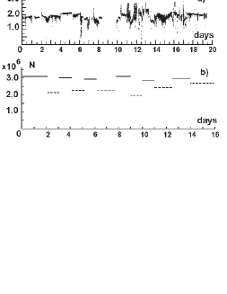
Fig. 4 shows the intensity of secondary beams in beamline 2 and in the set-up at beamline 23 in the and work regimes. For a time about 27 days, the Si19 crystal has obtained an irradiation of the order of 1020 proton/cm2. Herein the crystal channeling properties have not changed, as comes directly from the measurements of beam extraction efficencies in the beginning (442 %) and in the end (432 %) of the run.
The first experience of the work with the above-considered system, although satisfied the physicists, has also revealed ways for further advancement (improvement of the local orbit distortion systems stability, possibility to increase the intensity in the and regimes on the set-up of beamline 23 etc.).
3 Further plans
As computations show, the efficiency of beam extraction can be raised with use of shorter (order of 1 mm and less) bent crystals.
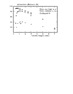
Besides the high energy accelerators, crystals of this kind could be used also at low energy accelerators. Basic problem here is to bend such a crystal at an angle of 0.5-1.5 mrad. One of radical solutions for this problem is to obtain bent crystals in the process of crystal growth [5]. Another direction, now in progress in IHEP, is related to the methodics of bending a short strip.
The above said is illustrated by Fig. 5 where plotted are the calculations of extraction efficiency for the most interesting, still-unstudied region, and the experimental data obtained at the IHEP accelerator.
References
- [1] A. G. Afonin et al., JETP Lett. 67, 781 (1998) [Pisma Zh. Eksp. Teor. Fiz. 67, 741 (1998)].
- [2] A. G. Afonin et al., JETP Lett. 68, 568 (1998) [Pisma Zh. Eksp. Teor. Fiz. 68, 544 (1998)].
- [3] A. G. Afonin et al., Phys. Lett. B 435, 240 (1998).
- [4] A. A. Arkhipenko et al., Instrum. Exp. Tech. 43, 11 (2000) [Prib. Tekh. Eksp. 43, 16 (2000)].
- [5] M.B.H.Breese, Nucl. Instr. Meth. B 132, 540 (1997)