THE NUMI HADRONIC HOSE
Abstract
The Neutrinos at the Main Injector (NuMI) beam supplies an intense beam to the Main Injector Neutrino Oscillation Search (MINOS). The ’s are derived from a secondary beam that is allowed to decay within a 675 m decay tunnel. We are developing a continuous toroidal magnetic focusing system, called the Hadronic Hose, to better steer this secondary beam. The Hose will both increase the net neutrino flux reaching the MINOS detectors and reduce systematic differences in the neutrino energy spectra at the two detectors due to solid angle acceptances.
1 NUMI BEAMLINE
NuMI is a tertiary beam from the Main Injector [1]. Protons will be extracted via single turn extraction (sec pulse, cycle time sec.) from the Main Injector and focused downward by 58 mRad, where they strike a 0.94 m graphite target to produce the secondary hadron (, ) beam. It is anticipated to achieve protons/pulse.
Two toroidal magnetic ”horns” sign- and momentum-select the secondary beam and are moveable so as to achieve different neutrino energy spectra[2]. After being focussed forward, the hadrons enter a 675 m long, 1 m radius evacuated decay volume. Soft pions tend to decay in the upstream end of the decay pipe, so must decay at wide angles to send neutrinos to the MINOS detectors, while stiff pions tend to travel further down the decay pipe.
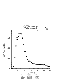
MINOS [3] is a 2-detector neutrino experiment. The near detector measures the neutrino energy spectrum and rate produced at Fermilab. A second, “far”, detector is located 735 km away in the Soudan mine in Minnesota. The far detector looks for differences from the near spectrum that could be explained by new physics such as neutrino oscillations. Figure 1 shows the expected spectra in the two detectors in the absence of new physics.
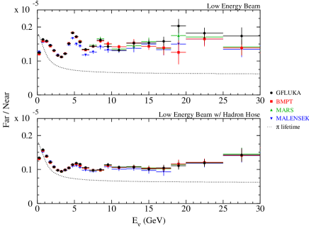
It is desirable to have the spectra at the two detectors as similar as possible. Differences due to beamline acceptances, etc., must be characterized by the “far-over-near ratio” (see Figure 2), which is the factor by which the near spectrum would be multiplied to predict the far spectrum in the absence of new physics. Systematic errors on this factor limit the ultimate reach of oscillation searches.

The neutrinos in the peaks of the spectra of Figure 1 come from pions focused by the horns, whereas the neutrinos in the high energy tail come from poorly focused pions (pions that travel through the necks of the horns). The high energy tail is nonetheless crucial to the experiment because for low signals it provides us it provides a control sample to demonstrate a region without oscillation effects.
2 Hadronic Hose
It is proposed to add an additional focusing system for the secondary pion beam, the ’Hadronic Hose.’ It consists of a 2.38 mm diameter aluminum wire at the center of the NuMI decay tunnel and carries a 1000 A peak current pulse. The current provides a toroidal magnetic field which focuses positive particles back toward the center of the NuMI decay pipe. A typical meson executes 3-4 orbits around the wire over the length of the decay pipe. The idea is similar to a proposal by van der Meer, but here implemented for a neutrino beam.[4]
The hadronic hose contributes two essential features: (1) ’s and ’s that otherwise diverge out to the decay pipe walls and interact before they decay are given a restoring force back to the decay pipe center. Thus, ’s/’s travel farther and have a greater chance to decay, so the neutrino flux is increased (see Table 1); (2) the pion orbits effectively randomize the decay angle between the pion direction and the neutrino that hits the MINOS near and far detectors. Because of the kinematic correlation between neutrino energy and decay angle, this randomization is important to make the neutrino energy spectra in the near and far MINOS detectors more similar (see Figure 1). Differences in the far-over-near ratio due to different predictions[6, 5, 7, 8] of pion cross sections off the target are reduced (see Figure 2).
| Beam | Flux in peak | Overall Flux |
|---|---|---|
| PH2LE | 261 | 474 |
| PH2LE-HH | 327 | 732 |
| PH2ME | 1077 | 1268 |
| PH2ME-HH | 1281 | 1675 |
| PH2HE | 2694 | 2745 |
| PH2HE-HH | 2870 | 2983 |
Besides minimizing the experiment’s sensitivity to variations in pion productions cross sections, the Hadronic hose loosens accuracy criteria for other beamline components. The eccentricity of the inner conductor of Horn 1, required to be 0.08 mm at its neck position in order to minimize fringe fields which affect high energy pions, is relaxed to 0.12 mm. The spatial alignment of Horn 1 transverse to the beamline is relaxed from mm to mm. Relative current variations between the two horns can now be as large as % (c.f. %). Finally, the alignment of the straightness of the NuMI decay pipe, previously required to be within 9 mm all along its 675 m length, is now relaxed considerably. The hose guides the beam along even long arc-like excursions in the beamline geometry.
3 Hose Mechanical Design
The hadronic hose is built up out of 72 9 m sections of wire, each of which is an independent circuit. The electrical connection of each section to the transmission line passes through an electrical feedthrough in the decay pipe wall consisting of an aluminum pin and ceramic insulating jacket. The wire is suspended at the center of the decay pipe by 0.1” diameter Invar guide wires attached to the decay pipe at m intervals along the decay pipe. The guide wires are insulated from the decay pipe wall by ceramic pins. The ceramics will be exposed to Rad/year in NuMI. Tensioning springs at the end of the wire maintain a 2 lb. tension on the wire. A 2 m hose segment at the most upstream end of the decay pipe is left unpulsed and absorbs some of the unreacted proton beam.

4 Hose Electrical Design
Each hose segment is connected in parallel to a transmission line that runs down the side passageway of the decay tunnel, through a 3:1 transformer. The transmission line is energized with a 5000 V pulse 620 sec in duration. The upstream end of a hose segment is ’center-tapped’ to the same transformer as the downstream end of the preceding hose segment. All the hose segments are effectively in series, receiving the same currents to within 1 A according to simulations, where the difference is due to the 80o C temperature variation of the hose segments inside the decay tunnel. If a hose segment should fail and sever during operation, all the current passes through the transmission line.
The 620 sec RMS, 1000 A peak, pulse causes a 250 V voltage drop across each of the 9 m segments, dominated by the inductive voltage drop ( for the wire in the 1 m vacuum decay pipe). The resistance of the 9 m long, 2.4 mm diameter Al1350 wire is m, giving a resistive drop of 83 V. This current pulse deposits J into the wire. At 250 V, the voltage on the wire is well below the breakdown point measured for gas pressures of 0.1-1.0 Torr expected in NuMI (see Figure 4).
5 Hardware R&D


Pion interactions in the wire material motivate the choice of low wire (see Figure 3), and also small (2.4 mm) diameter wire to avoid reductions in neutrino flux. Aluminum alloy 1350 has a conductivity approximately 80% of pure copper. Pure aluminum experiences plastic flow (“creep”) at elevated temperature, and we have measured several alloys’ creep rates at various temperatures and tensions on the wires over a period of 400 days by placing them in a high temperature vessel (see Figure 4). In the NuMI beam it is expected the wire will operate at 120 - 150 oC, at which the creep rate is low enough to allow expansion into the 20 cm gaps between wire segments over 10 years of operation without causing voltage breakdown between segments.
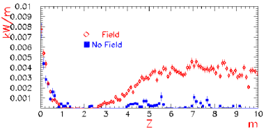
The hose wire is hit by the protons that didn’t react in the NuMI target. Approximately protons per beam pulse enter the decay pipe with a cm spot size after multiple scattering in the target, and this cloud is almost perfectly focused into the hose wire.111It is an interesting point that the secondary pion beam does not all interact in the hose wire as well. In contrast to the proton beam, the pions multiple scatter through the horn material (20%), so acquire a component of their momentum in the ’azimuthal’ direction looking down the beamline which causes their orbits in the hose field circle the wire. The energy deposition in the hose wire, as calculated using the MARS[5] beamline Monte Carlo, agrees qualitatively with the energy deposition expected from protons focused back into the hose further downstream in the decay tunnel and from the proton beam directly hitting the end of the first hose wire segment (see Figure 5). The peak of this energy deposition is 18 m downstream in the decay pipe, and is 4.5 W/m.
The hose wire dissipates heat largely through conduction through the residual gas (Torr in the decay pipe) or through blackbody radiation. The hose wire is coated with a 17 m thick aluminum oxide layer 222This coating also reduces the creep rate by 10%. to improve its emissivity from 0.1 for bare aluminum to . The emissivity has been measured in a 25 foot long, 6” diameter vacuum chamber with blackened interior walls and a hose wire running down its center at DC current to provide a known power in. The temperature was inferred from the elongation of the wire viewed through a window and the coefficient of thermal expansion measured for the wire.
6 Conclusions
We have investigated the potential impact of a new focusing system, the Hadronic Hose, for conventional neutrino beams. Such a system is being considered for the NuMI beam at Fermilab, and may be of benefit to future conventional ’super beams’ because of its increase in neutrino flux and ability to control systematic uncertainties due to particle production in the target or imperfections in the rest of the neutrino beam.
References
- [1] J. Hylen et al. “Conceptual Design for the Technical Components of the Neutrino Beam for the Main Injector (NuMI),” Fermilab-TM-2018, Sept., 1997.
- [2] V. Garkusha, F. Novoskoltsev, and V. Zarucheisky, “The PH2M Two Horn Focussing System for the NuMI Project,” Fermilab note NuMI-B-471 (1999).
- [3] The MINOS Collaboration, “The MINOS Detectors Technical Design Report,” Fermilab NuMI-L-337, Oct. 1998, S. Wojicki, spokesman.
- [4] S. van der Meer, The Beam Guide, CERN preprint number CERN-62-16, April 17, 1962.
- [5] N.V. Mokhov, “The MARS Monte Carlo”, Fermilab FN-628 (1995); O.E. Krivosheev et al., Proc. of the Third and Fourth Workshops on Simulating Accelerator Radiation Environments (SARE3 and SARE4), Fermilab-Conf-98/043(1998) and Fermilab-Conf-98/379(1998).
- [6] M. Bonesini, A. Marchionni, F. Pietropaolo, and T. Tabarelli de Fatis, “On Particle Production for High Energy Neutrino Beams,” Eur. Phys. J. C20, 13-27 (2001).
- [7] A.J. Malensek, “Empirical Formula for Thick Target Particle Production,” Fermilab FN-341, Oct. 1981.
- [8] GEANT Detector Description and Simulation Tool, CERN Program Library, W5013 (1994).
- [9] J. Hylen et al., “Proposal to Include Hadronic Hose in the NuMI Beamline,” Fermilab NuMI-B-542, Oct. 1999.
- [10] J. Hylen et al., “Technical Design Report for the Hadronic Hose”, NuMI-B-610 (2000).