T10 SND UPGRADE
Abstract
The program of upgrade of the Spherical Neutral Detector for future experiments at a new VEPP-2000 collider is presented. Modernization includes upgrades of electromagnetic calorimeter, tracking system, detector electronics, data acquisition system, and offline software.
It is also planned to equip the detector with two new subsystems: particle identification system based on aerogel Čerenkov counters and external electron tagging system for physics.
1 Introduction
The Spherical Neutral Detector [1] was designed for experiments at VEPP-2M collider in the energy range from 0.36 to 1.4 GeV. These experiments were carried out since 1996 till 2000. The SND collected about 30 pb-1 of integrated luminosity which corresponds to 7, 4 and 20 millions produced , and mesons, respectively. The main physical goals of SND were precise measurements of the magnetic dipole decays of , and , observation and study of the electric dipole decays , , measurement of the hadron production cross sections [2, 3]. The study of the hadron cross sections will be continued at VEPP-2000 [4]. This machine is being built in Novosibirsk and will cover a poor studied energy region from 1.4 up to 2.0 GeV.
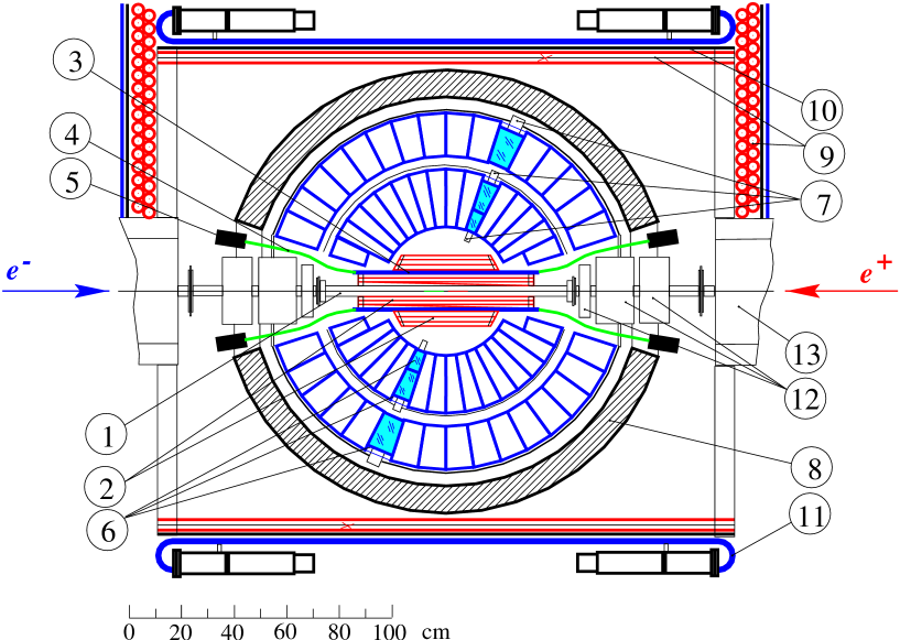
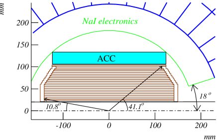
The current layout of the detector is shown in Fig. 1. The main part of SND is the electromagnetic calorimeter based on NaI(Tl) crystals. Inside the calorimeter a tracking system is placed. It consists of two drift chambers with a cylindrical scintillation counter between them. The calorimeter is surrounded by a 12 cm thick iron absorber and a segmented muon system which provides both muon identification and cosmic background suppression. Each segment of this system consists of two layers of streamer tubes and a plastic scintillation counter.
For experiments at VEPP-2000 a part of detector subsystems will be modified.
-
•
The new design of the collider interaction region requires a change of sizes of the tracking system. The new drift chamber is being designed now.
-
•
The measurements in the drift chamber can provide separation only up to 1200 MeV center-of-mass energy. To cover completely the energy region of VEPP-2000 we plan to install an additional system for particle identification based on aerogel Čerenkov counters.
-
•
The new phototriodes will be installed in the third calorimeter layer. The old ones significantly degraded during experiments at VEPP-2M.
-
•
The high luminosity (up to cm-2s-1 at 2 GeV) of the new machine and possible increase of beam background require modification of the digitizing electronics and new data acquisition system.
-
•
The combination of the relatively low energy and high luminosity at VEPP-2000 gives a good possibility for study of physics at low invariant masses . For this task, detector will be equipped with a system for detection of the scattered electrons.
2 Calorimeter
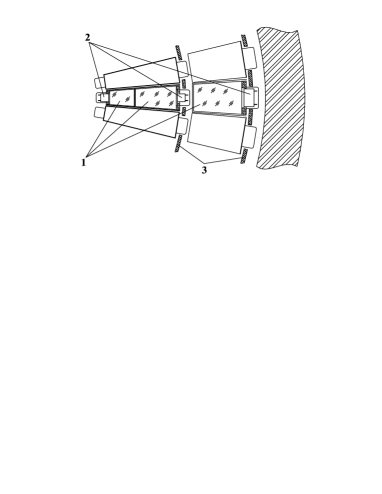
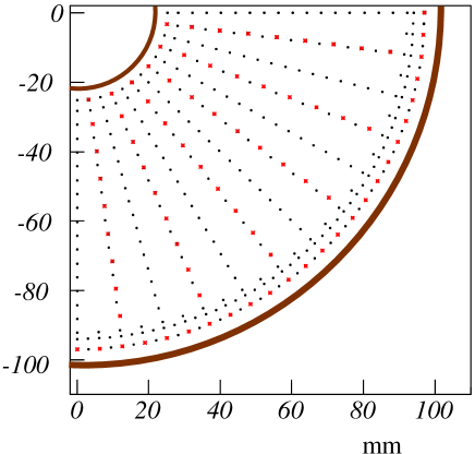
The calorimeter has a spherical shape which provides relative uniformity of response over the whole solid angle. It consists of 1632 NaI(Tl)counters arranged in three layers. Pairs of counters of the two inner layers are sealed in common 0.1 mm thick aluminum containers and fixed to an aluminum supporting hemisphere (Fig.2). Behind it, the third layer is placed. The gap between the adjacent crystals of one layer is about 0.5 mm. The total calorimeter thick is 13.4 (34.7 cm) with 2.9, 4.8 and 5.7 in the first, second and third layers, respectively. The total mass of NaI(Tl) is 3.5 t.
The calorimeter covers polar angle between 18 and 162 degrees. The polar angle dimension of crystals is 9 degrees. The azimuthal angle dimension is 9 degrees in “large” polar angle region and 18 degrees in the rest part. Each calorimeter layer contains crystals of eight different shapes.
The scintillation light signals from crystals are detected by vacuum phototriodes. The light collection efficiency varies from 7% to 15% for crystals of different layers. The phototriode quantum efficiency is about 15% and the gain is about 10. The electronic channel of the calorimeter consists of the charge sensitive preamplifier, shaper and 12-bit ADC. The equivalent sensitivity of electronic channel is about 0.25 MeV per ADC bit. The equivalent noise lies within the 150-350 keV range.
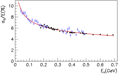
The calorimeter energy resolution is determined mainly by the fluctuations of the energy losses in passive materials before and inside the calorimeter, leakage of shower energy through the calorimeter and nonuniformity of the light collection. The most probable value of the energy deposition for photons is about 93% of their energy. The dependence of the calorimeter energy resolution on photon energy is shown in Fig.3 and can be approximated as:
The calorimeter angular resolution on photon energy is described by the following formula:
The crystal width approximately matches the transverse size of an electromagnetic shower in NaI(Tl). Two showers can be distinguished if the angle between them is larger then 9 degrees. If this angle exceeds 18 degrees the energy of the showers can be measured separately without a loss of accuracy.
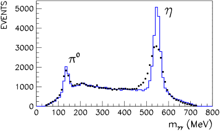
The two-photon invariant mass distribution of process in the energy region of meson resonance is shown in Fig.4. The raw and mass resolutions are 11 MeV and 25 MeV, respectively. In the analysis of most part of physical processes at SND the procedure of kinematic fitting is used. This procedure allows to distinguish different processes and improves the energy resolution. The effect of kinematic fit to the invariant mass distribution is demonstrated in Fig.4. The improvement of mass resolution by a factor 1.5 is clearly seen.
3 Tracking system
The new tracking system consists of a drift chamber and a proportional chamber in the common gas volume (Figs.5 and 6). The gas volume has cylindrical shape with an inner radius of 2 cm and an outer radius 10.3 cm. Its length varies from 30 cm to 26 cm.
Inside the gas volume there are 10 layers of sense wires. The inner 9 layers is the drift chamber consisting of 24 jet-type cells. The last outer layer is the proportional chamber used for measurement of Z coordinate. Both cylindrical walls have copper cathodes divided into strips transverse to wires with the step of 6 mm on their internal side. Another side of the walls are used for cathode signal output. The inner and outer cathodes have 128 and 152 strips, respectively. Both chambers contain 312 sense and 984 field wires. The sense wires are made of gold-plated tungsten with a diameter of 15 m. The field wires are 100 m bronze-plated titanium wires. In the drift chamber a 0.3 mm staggering of the sense wires in azimuthal direction is used to resolve the left/right ambiguity. The chamber will operate with a 90%Ar + 10%CO2 gas mixture.
The drift chamber electronics has to provide the drift time measurement and the amplitude measurements from both ends of sense wire under very hard background condition. The expected background rate of individual wire is up to 50 kHz. For time measurement, the front of the sum signal from both ends of the wire is detected and the arrival time is digitized with 1 ns resolution. The results of two time measurements during 1 s trigger latency is written to minimize the dead time. For amplitude measurement, a 10-bit 40 MHz FADC is used. The total charge can be obtained as a sum of about 12 amplitude measurements. The FADCs of the same kind are used to measure amplitudes of signals from cathode strips.
The expected drift chamber spatial resolution in azimuthal plane is about 150 m. Z-coordinate will be measured by the charge division method. The obtained in the test measurements with 40 MHz FADC corresponds to Z-resolution of 1-1.5 mm for different chamber layers. The cathode strips provide 2 additional measurement of Z with an expected accuracy of 0.3-0.6 mm depending on the track polar angle. The overall track system angular resolution is 0.2 degrees in both azimuthal and polar directions.
The measurements in the drift chamber give a possibility to separate and mesons with momenta up to 300 MeV/c.
4 Particle identification system
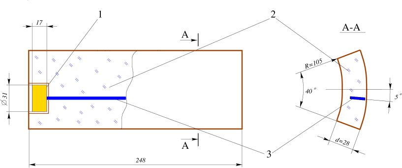
The SND identification system is based on Čerenkov threshold counters and should provide separation in the momentum region from 300 MeV/c to 870 MeV/c, which is maximal meson momentum at VEPP-2000. The aerogel with relatively large refractive index equal to 1.13 was chosen as a Čerenkov light radiator. The corresponding threshold momenta for and mesons are 246 and 938 MeV/c, respectively.
The identification system is a 25 cm long cylinder surrounding the tracking system (Fig.5). The inner cylinder radius is 10.5 cm. The width is 2.8 cm. The system consists of 9 equal counters with an azimuthal size of 40 degree (Fig.7). For the Čerenkov light collection, the wave length shifters (WLS) are used [7]. This method allows to diminish a number of the detector channels but leads to a possibility of misidentification for particles struck into WLS. In SND case the WLS azimuthal size is 3 mm and possibility of the particle misidentification is about 5%. The WLS light is detected by a compact photomultipliers with microchannel plates. For SND geometry, the expected number of the photoelectrons from an ultrarelativistic particle is about 10.
5 Electron tagging system
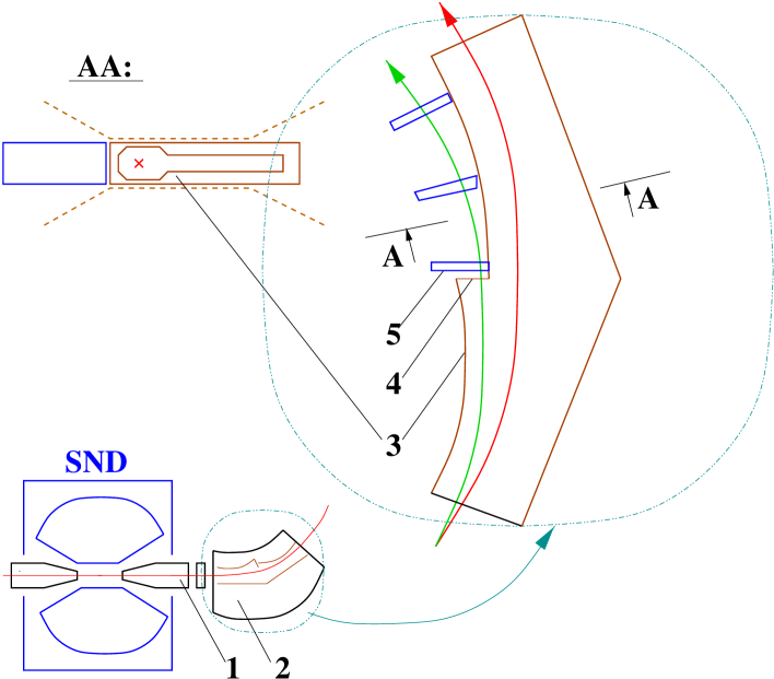
The VEPP-2000 gives a good possibility for study of physics at low invariant mass. The SND detection efficiency is about 50% for processes. The integrated luminosity of 150 pb-1 at 2 GeV (1 month at expected luminosity of cm-2sec-1) corresponds to , , , 2000 , 1000 produced in the photon-photon collisions. To successfully select two photon events from the beam background and the events of annihilation we plan to install the system for detection of the scattered electrons. The project of the electron tagging system is under study now. The one of possible designs is shown in Fig.8. The two set of the electron detectors are placed inside the bending magnets of the collider near the interaction region. The electron detector can be a GEM (gas electron multiplier) based detector with two coordinate readout. The presented system can provide the double tag efficiency of 15-25% in the invariant mass region from 300 to 1000 GeV and the mass resolution of about 5 MeV.
6 Data acquisition system
The SND data acquisition system is based on KLUKVA electronics standard [8] developed at BINP. One KLUKVA crate holds up to 16 data conversion (DC) modules, first level trigger interface (IFLT) and readout processor (RP) modules. The DC modules provide fast logical and analog signals, which are transfered via KLUKVA bus to IFLT modules for further use in FLT. The digitized data are extracted from the DC modules by RP with 100 ns cycle. The SND digitizing electronics occupies 16 KLUKVA crates.
The first level trigger system uses the following information:
-
•
total energy deposition in calorimeter,
-
•
160 logical signals from calorimeter towers (25 MeV threshold);
-
•
216 logical signals from drift chamber wires.
The FLT logic is implemented as a pipe line working at 40 MHz clock rate. The FLT decision latency is about 1 s. The FLT rate in the experiments at VEPP-2000 is expected to be about 1000 Hz.
The most part of KLUKVA modules including RP will be modified for new experiments. The pedestal subtraction and zero suppression will be performed in the DC modules. As a result an average event size will be about 3 kB. The time needed for this event digitization and reading into RP modules is about 30 s. New RP module provides data exchange with online computer via Ethernet network.
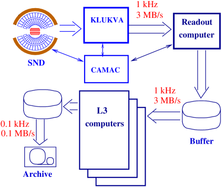
A schematic view of the SND data acquisition system is shown in Fig.9. The raw SND data are read by the Readout computer. The average data flow at this stage is about 3 MB/s. The Readout computer builds events and writes data into buffers on SCSI disks shared by several computers. The L3 processes (4 or more) taking data from buffers provide event packing, partial reconstruction, filtering and recording. This DAQ structure allows to increase an event processing rate proportionally to the number of L3 processes. The resulting output data flow is expected to be about 0.1 MB/s.
7 Offline software
Present FORTRAN-based offline programs will be replaced with object-oriented framework, which supports simulation, reconstruction and analysis activities. New framework exploits the experience obtained in the work with the current offline and supports or extends their essential features. Similar projects that exists in HEP (e.g. BaBar framework) were also examined to find out possible weak and strong features.
The main framework concept is a module, which is basic processing unit consuming some data and producing more data. Every module can be parameterized during run time. Formalized description of modules is used by framework sequencer for the selection and ordering of minimal subset of modules for any given task. Data persistency services are made sufficiently abstract to allow implementation for different persistency technologies. The framework provides an interface for scripting languages. Together with a custom expression parser this gives a support for extensible run-time histogramming.
8 Conclusion
For experiment at VEPP-2000 a part of SND subsystems will be upgraded: the electromagnetic calorimeter, tracking system, electronics, online and offline software. Two new subsystems will be added to detector: aerogel Čerenkov counter and electron tagging system. All these changes significantly extend SND capabilities for studies of the physical processes in new energy domain.
References
- [1] M.N.Achasov et al., Nucl. Instr. and Meth. A449 (2000) 125.
- [2] M.N.Achasov et al., Nucl. Phys. A675 (2000) 391, e-print hep-ex/9910057.
- [3] M.N.Achasov et al., e-print hep-ex/0010077.
- [4] Talk given by I.Koop at this workshop.
- [5] M.N.Achasov et al., Phys. Lett B 474 (2000) 188.
- [6] M.N.Achasov et al., Phys.Lett. B459 (1999) 674.
- [7] M.Yu.Barnykov et al., Nucl. Instr. and Meth. A453(2000) 326.
- [8] V.M.Aulchenko et al., Nucl. Instr. and Meth. A405(1998) 269.