A Fast High Resolution Track Trigger
for the H1 Experiment
Abstract
After 2001 the upgraded collider HERA will provide an about five times higher luminosity for the two experiments H1 and ZEUS. In order to cope with the expected higher event rates the H1 collaboration is building a track based trigger system, the Fast Track Trigger (FTT). It will be integrated in the first three levels (L1–L3) of the H1 trigger scheme to provide higher selectivity for events with charged particles. The FTT will allow to reconstruct 3-dimensional tracks in the central drift chamber down to 100 MeV/c within the L2 latency of 23 s. To reach the necessary momentum resolution of 5% (at 1 GeV/c) sophisticated reconstruction algorithms have to be implemented using high density Field Programmable Gate Arrays (FPGA) and their embedded Content Addressable Memories (CAM). The final track parameter optimization will be done using non-iterative fits implemented in DSPs. While at the first trigger level rough track information will be provided, at L2 tracks with high resolution are available to form trigger decisions on topological and other track based criteria like multiplicities and momenta. At the third trigger level a farm of commercial processor boards will be used to compute physics quantities such as invariant masses.
Index Terms:
Trigger, Fast Track Trigger, Track Trigger, FPGA, Content Addressable Memory, CAM, DSP, H1 Collaboration, HERA ColliderI Introduction
With the HERA collider at DESY 920 GeV protons are collided with 27.6 GeV electrons (positrons) every 96 ns. At one of the interaction points the H1 detector is located, an omni-purpose detector described in [1]. One of its main components is the central jet chamber (CJC) which consists of two concentric drift chambers, the inner CJC1 and the outer CJC2, with 24 and 32 layers of wires, respectively. Its signals will be the basic input for the high resolution track trigger described in this paper.
H1 uses a four level multi-stage trigger system (L1-L4) of which the first level [2] is a fully pipelined, dead time free hardware trigger with a decision time of 2.3 s, reducing the 10 MHz input rate by more than four orders of magnitude. The L1 decision is refined by L2 [3] within a fixed time of 23 s. Subsequently the detector read-out starts which in total takes about 1 ms but can be aborted by a negative decision generated in parallel by trigger level 3. To have a beneficial effect on the dead time the L3 decision should be available not more than 100 s after the read-out has started.
After an event has successfully been read out at the front end pipelines are restarted. Events are collected via an optical fiber ring, sent and buffered at a filter farm (L4) where they are fully reconstructed within some 100 ms. A detailed description of the H1 data acquisition system can be found in [4].
To study rare interactions with high precision, the HERA ring will be upgraded providing about a factor of five larger luminosity from 2001 onwards. The increased and background rates will however place a considerable strain on the H1 data acquisition. This necessitates an upgrade of the existing trigger system to provide better selectivity for the many exclusive final states exhibiting characteristic track based topologies – especially those containing heavy quarks – with rather small cross sections and low transverse momentum final state particles.
In contrast, events with a high momentum transfer 100 GeV2 can efficiently be triggered by calorimeter based signals with the present system also after the upgrade. No such possibility exists for events at lower and additional selection power is needed. Hence the H1 collaboration is building a Fast Track Trigger (FTT) which is able to find and reconstruct tracks and particle resonances at the first three trigger levels and provides trigger signals derived from track based quantities. The development of such a track trigger performing these sophisticated tasks within the tight time constraints given by the H1 trigger system has only become possible with the recent improvements in size and speed of available electronic components.
II The Fast Track Trigger
The FTT functionality is based on CJC information derived from four groups of three layers of wires each, three of them inside CJC1 and one inside CJC2 as shown in figure 1, which also displays the geometrical cell structure of both chambers. It is designed to handle up to 48 tracks which is sufficient for about 98% of the events of interest.
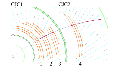
After digitizing the drift chamber signals a search for track segments within a group of three drift chamber hits is performed in each of the four radial trigger layers. A subsequent coarse track segment linking is completed within 2.1 s to contribute to a level 1 trigger decision based on track multiplicities and coarse cuts. A positive L1 decision triggers a refined track segment search reusing the FTT L1 hardware. The result is used by the second level FTT where the track segments have to be linked and fitted within 20 s including the determination of event quantities like a refined track multiplicity, momentum sums and invariant masses for low multiplicity events. The track parameters of the fitted tracks are sent to FTT L3 where a full search for particle resonances is performed within 100 s and the L3 track information is either used directly or in combination with information from other trigger subsystems to generate a final L3 decision.
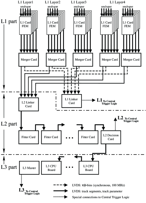
The different components of the FTT are schematically shown in figure 2 and will be described in detail below.
II-A Hit and Track Segment Finding at L1
Adapter cards will be used to tap selected analog CJC signals from the existing drift chamber readout. At the analog part of the so called Front End Modules (FEM) the signals of both wire ends are digitized at 80 MHz using a common 8 bit linear dual FADC (AD9288), where 15 FADCs are mounted on one board to serve 5 neighboring drift chamber cells. The main part of the following digital signal processing is done by 5 Altera APEX 20K600E FPGAs [5], one for each group of wires. Hit finding is performed by looking for pulses exceeding the noise level and extracting their precise time information with a precision of 2-3 ns. For each hit the -coordinate is obtained by a charge devision technique based on the signals from both wire ends. A resolution of =6 cm is expected to be achieved.
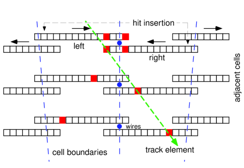
For the track segment finding hits are fed into 80 MHz shift registers implemented into the mentioned FPGAs. A first coarse track segment finding is done by logically ORing four adjacent entries effectively reducing the synchronization frequency to 20 MHz. For each HERA bunch crossing a parallel search for genuine track segments is performed in all four trigger layers and all cells consisting of three wires each. To account for tracks crossing cell boundaries the segment finding is extended using selected wires from neighboring cells. The main principle is shown in figure 3. Any track is characterized by hits in the parallel shift registers forming basically straight lines. Left-right ambiguities are resolved automatically when linking the track segments at the following stage. In order to perform the track segment finding within the limited time given by the L1 latency, the corresponding algorithms have to be implemented in a highly parallel and flexible way. The necessary resources are provided by the new high density FPGAs nowadays available and their embedded CAM functionality.
CAMs (Content Addressable Memories) can be regarded as inverse RAMs (Random Addressable Memories) where the input patterns are compared with pre-loaded values and matches are indicated by either signaling the corresponding address location bit “high” (unencoded output) or by generating a list of matching addresses (encoded output). They are commonly used for networking and computing, e.g. transformation of IP addresses, data compression and as cache tag allowing fast access to memory data. Thus CAMs open a wide field of applications, in particular in high energy physics where search tasks like track linking, cluster finding and pattern recognition are common standard.
The integration of CAMs in FPGA devices (e.g. Altera [5]) allows complex high speed applications running at 100 MHz frequencies and more. As an example the usage of tag fields is given. When operating a CAM in the so called encoded mode a list of addresses of valid match locations is generated. In a second step these addresses are then used to access additional information from a parallel RAM. This tag field method is implemented in the Fast Track Trigger to assign track parameters to valid hit combinations.
II-A1 Generation of L1 Trigger Signals
Every HERA bunch crossing a coarse track segment finding for all groups of three wires is performed in a pipelined manner. The coarse time information synchronized at 20 MHz and buffered in shift registers is presented in parallel to up to 64 CAMs implemented into a single FPGA. The inputs are compared to pre-calculated patterns of valid tracks originating from the nominal vertex. The CAMs are running in the unencoded mode with each output bit directly corresponding to a single bin in the - track parameter space, where represents the track curvature and the inclination in a local coordinate system.
The track segment parameters from the 5 FPGAs at the front of each FEM are collected and sent to an I/O controller. Via intermediate Merger Cards the track segment information from 30 FEMs is transmitted to the L1 Linker Card. For data transmission a high speed LVDS Channel Link [6] running at 100 MHz (600 MBytes/s) is used.
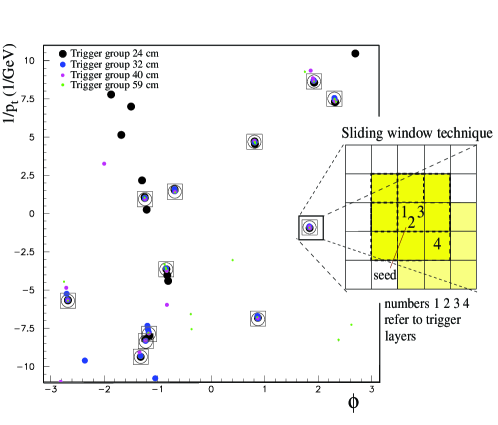
In a last processing step the track segment information from the four different trigger layers are linked by a 33 sliding window technique searching for coincidences in the - track parameter space in at least 2 out of 4 trigger layers. Since most track segments can only be linked for a single bunch crossing an event can be generated looking for a maximum in the number of linked tracks. Besides such a general signal topological criteria and track multiplicities as a function of different transverse momentum thresholds may also be used to form a first level trigger decision.
II-A2 Refined track segment finding
After an event has been accepted by the first trigger level the shift registers are held and more refined track segments to be used at level 2 are extracted. For this the coarse track segments based on the 20 MHz digitization are serialized and expanded by restoring the original 80 MHz information. This improves the precision in and substantially. In addition the -position of hits stored earlier in parallel shift register is added to obtain the full 3-dimensional track information. Before finally sending the refined track segments via the I/O controller to the second level stage a further validation has to be performed to guarantee that the more precise track parameters satisfy the criteria of a track originating from the vertex. This is done by checking for valid masks pre-loaded into an SRAM serving as look-up table (LUT). If the refined segments match pre-calculated masks a validation bit is set and the corresponding and values are read from a second LUT.
- values and the -coordinates of the corresponding hits are transferred via the “Merger Cards” to the second level of the FTT where the individual segments are combined to global tracks.
II-B L2 Track Linking and Fitting
The level 2 stage of the FTT performs a track linking in two dimensions in - space followed by a full 3-dimensional track fit also including the transfered -position. About 20 s after a positive L1 decision FTT L2 has to provide information to the central trigger logic. In collaboration with SCS [7] a generic multi-purpose FTT L2 board is developed which may be used for several purposes: data merging, track linking, track fitting and generation of trigger signals. This is realized by mounting a high density APEX 20K600E FPGA and optionally up to 4 DSPs onto the board. Flexible I/O configurations are realized by “Piggy Back” cards to interface the 100 MHz LVDS channel links.
Equipped with four Piggy Back cards Merger Cards are used to bundle the data coming from FTT level 1 onto the “Linker Card” where they are fed to the high density FPGA for linking. Track segments from the four trigger layers are buffered in RAMs and the and values of each layer are used to fill 2-dimensional histograms with 40 bins in and 640 bins in . ¿From the RAM a list of track seeds in the - plane is build starting at the first trigger layer. The list of track segments is processed and 25 parallel CAMs per layer are used to find track segment clusters in a single processing step. By a 33 sliding window technique the exact peak position is then determined and in case of a valid track the full track information is restored from the parallel RAM. The basic principle of the track linking procedure is illustrated in figure 4.
The full track information of the linked tracks is sent to the “Fitter Cards” which are equipped with 4 floating point DSPs (Texas Instruments TMS320C6701 [8]). A load balancing algorithm is used to share the tracks among different DSPs. The procedure starts with a non-iterative fit in the - plane [9] constraining the tracks to originate from the primary vertex. Afterwards a fit in the - plane is performed, using additional information on the -position of the vertex provided by the H1 trigger system. All successfully fitted tracks are collected by the “L2 Decision Card” where track based event quantities like momentum sums are used to generate the final L2 trigger signals. If the event is accepted by the second level trigger the complete set of 3-dimensional tracks is passed on to FTT L3.
II-C Searching for Particle Resonances
A farm of up to 16 single CPU VME boards is used to calculate an L3 trigger decision. Track information coming from FTT L2 are sent via a fast LVDS receiver-transmitter chain to special receiver boards. On these boards the data are buffered and using a 20 MHz FPDP (Front Panel Data Port [10]) sent via PMCs (PCI Mezzanine Cards [11]) to the local memory on the CPU boards. This mechanism ensures that all track data are available on each board after a maximum transmission time of 10 s leaving plenty of time for sophisticated analyses. The aim is to provide an environment where analysis groups can easily implement their analysis code. This is guaranteed by the use of a commercial real time operating system including standard compiler software to allow easy implementation of e.g. C-code. The final L3 trigger decision will be primarily based on the track information received from FTT L2 and a main task will be the search for particle resonances within a high multiplicity environment of up to 48 tracks. However, additional information from other first level trigger systems can be made available allowing for a more sophisticated decision based on correlations amongst different subdetectors.
III Simulated Performance
The different performance studies maybe categorized into (A ) timing estimates for the different algorithms to be implemented on FPGAs and DSPs done using specialized software [12, 13], and (B ) tests of the FTT track reconstruction abilities based on Monte Carlo programs. For both categories extensive simulations have been done showing that the Fast Track Trigger fulfills the demands of the existing system and the upgraded HERA collider.
| Level | Task | Latency |
| [cumulated] | ||
| L1 | Ionisation & drift time | 1.1 s |
| Analogue cable delays | 1.3 s | |
| Coarse track segment finding | 1.5 s | |
| Transmission to L1 Linker | 1.9 s | |
| Track linking | 2.0 s | |
| Trigger signal transmission | 2.1 s | |
| L1 Trigger decision | 2.3 s | |
| L2 | Track segment refinement | 3.5 s |
| Transmission to L2 Linker | 3.9 s | |
| L2 Linking (48 tracks) | 9.1 s | |
| Track fitting (48 tracks) | 12.9 s | |
| Generation of trigger signals | 21.9 s | |
| L2 Trigger decision | 23.0 s | |
| L3 | Transmission to FTT L3 | 30 s |
| L3 analysis & decision | 100 s |
III-A Timing
The FTT latencies of all three stages (L1–L3) are given in table I. The numbers in the table should be compared to the time constraints given by the H1 trigger system of 2.3 s, 23 s and 100 s for the overal L1, L2 and L3 decision time, respectively. While time requirements for FTT L1 are rather tight mainly due to the large delay which arises from the maximum drift time to the CJC sense wires, the demands on FTT L2 are less stringent. After the track linking step the remaining time for track based calculations of 9 s is long enough to even allow invariant mass sums in low multiplicity events to be completed. For the FTT L3 farm it has been checked that modern CPUs can cope with the combinatorial complexity of the search for e.g. the golden decay of mesons () within the required time 100 s.
III-B Physics Return
In order to allow for detailed performance studies a software package has been developed which simulates the digital part of the first, second and third level of the FTT. It has been used to obtain track resolutions, study efficiencies and to determine the robustness of the system concerning its dependence on the chamber performance. In addition different implementations of the available track finding, linking and fitting algorithms have been compared and could be optimized.
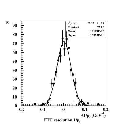
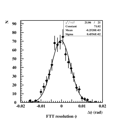
The FTT is designed to find tracks down to a transverse momentum =100 MeV. The expected resolutions relative to the nominal H1 reconstruction in and can be extracted from figure 5 giving and mrad.
To investigate the full power of the Fast Trigger up to level 3 the channel, , mentioned above has been analysed in detail revealing that overall efficiencies in excess of 80 % relative to a typical off-line selection can be achieved. The corresponding trigger rates can be kept reasonably low as needed not to incur excessive dead time at the early trigger stages.
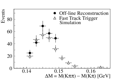
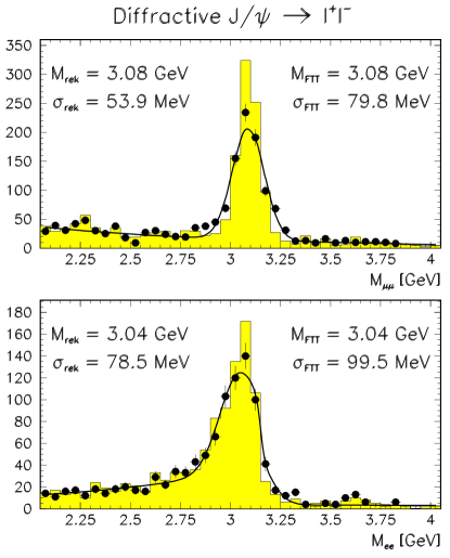
The FTT abilities up to L2 were tested by feeding low multiplicity H1 data of meson candidates into the simulation followed by a full analysis using the FTT tracks. The outcome of the invariant mass spectrum is compared to the one obtained using the standard H1 reconstruction software. Figure 7 shows the corresponding mass spectra for ’s decaying into muons and electrons convincingly showing the potential of the FTT. Further physics channels have been analyzed in a similar way leading to similar results.
Finally, in order to study the influence of the potentially larger background expected after the HERA upgrade, tracks from beam-gas background have been artificially added to genuine events. Furthermore, a decreased single wire efficiency, decreased -resolution and additional random noise were included in the simulation to test the stability of the system. No substantial performance loss has been observed for any reasonable scenario studied.
IV Conclusion
The H1 collaboration is in the process of building a Fast Track Trigger (FTT) to cope with the demands of the high luminosity HERA upgrade planned for 2001. It is based on novel technologies of integrated circuits making extensive use of the embedded CAM functionality of modern high density FPGAs and shall supply information to the first three trigger levels of the H1 triggering system. The FTT will be capable of performing complex algorithms such as fast track segment finding, track linking and fitting. Apart from simple track based quantities to be provided after the L1 latency of 2.3 s it will perform sophisticated analyses, such that momentum sums and invariant mass sums can be provided at the L2 (23 s) or L3 (100 s) decision time depending on event size and complexity of the calculations. Simulations show a high physics potential and a large selectivity of the new system.
References
- [1] I. Abt et al., “The H1 Detector at HERA”, Nucl. Instr. and Meth., vol. A386, pp. 310 & 348, 1997
- [2] F. Sefkow, E. Elsen, H. Krehbiel, U.Straumann and J. Coughlan, “Experience with the first level trigger of H1”, IEEE Transactions on Nuclear Science, vol. 42 pp. 900-904, 1995
- [3] T. Nicholls, M. Charlet, J. Coughlan, E. Elsen, D. Hoffmann, H. Krehbiel, H.-C. Schultz-Coulon, J. Schütt and F. Sefkow, “Concept, Design and Performance of the Second Level Trigger of the H1 Detector”, IEEE Transactions on Nuclear Science, vol. 45 pp. 810-816, 1998
- [4] W. Haynes, “Experience at HERA with the H1 data acquisition system”, Proceedings of the Int. Conference on Computing in High Energy Physics 1992, Annecy, France, pp. 151-161, 1992
- [5] Altera, http://www.altera.com, data sheet “APEX20K programmable logic device family”, version 2.06, March 2000
- [6] National Semiconductor, http://www.national.com, data sheet “DS90CR483/484: 48 bit LVDS channel link Serializer/Deserializer”, July 2000
- [7] Supercomputing Systems Company, Zürich, Switzerland, http://www.scs.ch
- [8] Texas Instr., http://www.ti.com, data sheet “TMS320C6701: Floating Point Digital Signal Processor”, May 2000
- [9] V. Karimäki, “Effective circle fitting for particle trajectories”, Nucl. Instr. and Meth., vol. A305, pp. 187, 1991
- [10] ANSI/VITA 17-1998
- [11] IEEE P1386.1
- [12] Quartus version 2000.05, http://www.altera.com/html/tools/quartus.html
- [13] Code Composer Studio 1.2, http://www-s.ti.com/sc/psheets/spra520/spra520.pdf