Fermilab-Conf-00/229 Sept2000 Charged Kaons at the Main Injector (CKM)
Abstract
The CKM collaboration is proposing to measure the branching ratio of the rare K decay at the Main Injector at Fermilab. Our goal is to be able to observe 100 events, for a Standard Model branching ratio of . This implies that we must be able to reduce the background to a few events at a reasonable cost.
1 The Physics
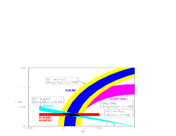
The branching ratio for the decay was first calculated by Inami and Lin [1] as an isospin rotation from . The measurement of the branching ratio of alone will allow one to obtain the magnitude of , the element in the Cabbibo Kobayashi Maskawa matrix, which controls Standard Model CP violation. In conjunction with the neutral channel decay and measurements in the B sector, this will provide an overconstrained measurement of both the real and the imaginary part of . This will address the question on CP violation: Can it be completely accounted for by the Standard Model. Figure 1 illustrates the proposed sensitivity of various experiments that will measure and , the CP violating parameters of the standard model.
The Standard Model predicts a branching ratio for the decay of in Buras’s unitarity triangle [2]. One event has been observed by the BNL experiment E787 in a stopped experiment. We propose [3] to measure the decay in flight of and obtain 70 events in 2 years of data taking . This will meet the precision suggested by the theory. An intermediate stage, the observation of 5-10 events, is the goal of an approved BNL experiment E949, which is the continuation of E787. Some members of the CKM and E949 are now working in collaboration with each other as two stages of a physics program.
2 The Background
One of the challenges of the experiment is to control the background which is 10 orders of magnitude larger than the expected signal.
2.1 The background
This decay, with branching ratio 21%, can mimic the signal if the two from the decay of the are undetected. It will be controlled by a combination of kinematic rejection and a photon veto system. The CKM detector must veto photons with a very high efficiency.
2.2 The background
In this decay , with a branching ratio 63.5%, the can be misidentified as a .This is controlled by a muon veto and RICH systems.
2.3 Background from Interactions
The interactions of the undecayed beam or daughter s contribute to the background. In order to minimize this contribution, as little material as possible should be encountered by the particles. This dictates the choice of the various detector elements.
3 The Apparatus
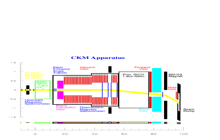
In Figure 2 are shown the detector elements which will be detailed below. To detect hadronic interactions before the decay volume entrance, a hadron calorimeter surrounding the beam (not described)is used .
3.1 The RICH and the Spectrometers
The charged particles in the reaction, namely the K and the are both measured by Ring Imaging CHerenkov counters (RICH) as velocity vectors and as momentum vectors in upstream and downstream spectrometers. The gas in the pion RICH is chosen in order to meet the low dispersion required for good resolution. In order to allow as little material in the beam as possible rather thin mirrors and windows are mandatory. This require the RICHs to operate at or near atmospheric pressure. These considerations have contributed to the choice of the K beam to be 22GeV energy and the radiator gas of the decay pion RICH to be neon. The momentum resolution achieved by the RICH is better than 1% for this configuration. The K and magnetic spectrometers use conventional trackers, silicon strips and straw tubes respectively. Straws have been chosen to minimize the material in the beam. They are 5mm in diameter with a 20 m sense wire, 5 to 8 straw layers per station (x,y,u,v). , with 150m hit resolution per layer. The straws are located in the vacuum decay volume.
3.2 The veto system
As already mentioned one of the main tasks of the experiment is to control the background from the decay. This points to the extreme importance of the veto system. The veto system has a component surrounding the decay volume, where the decay takes place and a forward component, after the RICH to deal with high energy ’s. We want to minimize interactions which are an important component of the non-Gaussian tails of the background. Therefore, the component surrounding the decay volume will be located inside the vacuum vessel with a vacuum of torr and we call this Vacuum Veto System (VVS). The VVS is made of a sandwich of plastic scintillator and lead 5mm/1mm each, stacked in modules 50 cm long and 40cm radially. There are over 80 such sandwich layers per module and 34 such modules in the VVS. There is a void of 50cm between each module which corresponds to an angle of incidence of degrees for . This angle is not reached by the photons coming from the decay kinematics . This allows us to reduce the volume and the cost by a factor two.
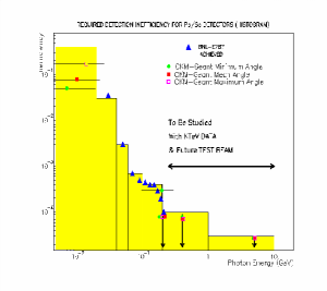
The required VVS detection inefficiency is given in Figure 3. In the region of medium energies the requirements have been achieved by E787 with a comparable veto system.
For the Forward Veto System (FVS) a choice of various techniques are avalaible, and are still under study. We are assuming, for the moment, a setup of Sc/Pb 5mm/1mm sandwiches for this calorimeter as well.
3.3 The Muon Veto
Another important component of the background is the which has a branching ratio of 63.5%. A muon veto follows the FVS. The non-interacting beam goes through a hole in the FVS and muon veto system and is dumped afterward by a magnetic field into the beam dump.
4 The Beam
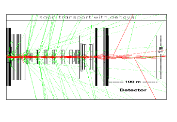
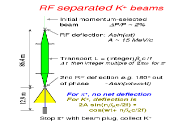
A very important component of our experiment is the beam. In order to get 6MHz of decays in the fiducial volume we need a 30 MHz beam with a ratio of of, whereas nature tends to provide far more ’s than K’s, shown Figure 4 and Figure 5. We will construct a new RF separated beam based upon 3.9 GHz transverse mode superconducting RF cavities, being developed at Fermilab for this purpose. We use a set of 2 RF cavities properly spaced from each other in order for the s to be deflected by the 1st cavity, and then deflected back by the same amount, by the 2nd cavity. The s are absorbed by a beam stopper. With the cavities phased this way, protons which arrive at the second cavity just one RF period behind the s are also undeflected. Ks, however, arrive in RF phase behind the and are deflected again with the same sign, causing most of them to miss the beam stopper. A cartoon of the operation is shown in Figure 6.
In Figure 4 we show the behavior of the component of the beam which after having been deflected back by the second cavity is stopped. Shown in the same figure are the s coming from decays in the beam line.
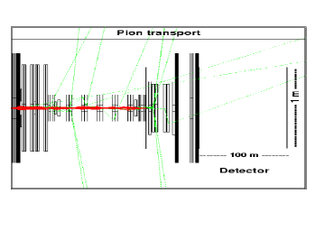
In Figure 5 the K component is shown with the decay s. The Ks which avoid the stopper are shown reaching the detector.
5 Status
We are in the process of building prototypes for the photon veto system, the straw tubes and the super-conducting RF cavities. Simulations are being done in parallel for both the straws and the veto systems as well as for the beam line design.
6 Conclusion
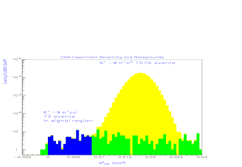
Figure 7 shows the expected signal and background after the photon vetos have been applied from two years of running as a function of the missing mass squared of the neutral system recoiling against the . 72 events survive in a signal region with 3 unvetoed and mismeasured event. The total background estimate for this sample, including , interactions and accidentals is events. Work is now underway to refine and improve our proposal with the intention of seeking approval in the spring 2001.
References
- [1] T. Inami and C.S. Lim, prog Theor.Phys. 65(1981)297.
- [2] A.J.Buras, hep-ph/9711217, TUM-HEP-299-97, Oct 97,(To appear in the proceedings of the Symposium on heavy Flavours, Santa Barbara, July7-11,1997).
- [3] FNAL Proposal, Charged Kaons at the Main Injector,April 15,98.