The DELPHI Silicon Tracker in
the global pattern recognition
Abstract
ALEPH and DELPHI were the first experiments operating a silicon vertex detector at LEP. During the past 10 years of data taking the DELPHI Silicon Tracker was upgraded three times to follow the different tracking requirements for LEP 1 and LEP 2 as well as to improve the tracking performance. Several steps in the development of the pattern recognition software were done in order to understand and fully exploit the silicon tracker information. This article gives an overview of the final algorithms and concepts of the track reconstruction using the Silicon Tracker in DELPHI.
1 Introduction
Since 1990 DELPHI has been operating a Silicon Tracker [1] in the barrel region close to the beam pipe. This detector has been upgraded [2] three times to follow the different tracking requirements for LEP 1 and LEP 2 as well as to improve the tracking performance. In its final upgraded version the Silicon Tracker [3] covers nearly the full polar angle down to . It is the innermost detector of the tracking system of the DELPHI detector [4], which is one of the most complex because of the presence of the Ring Imaging Cherenkov Counters (RICH) in the central (barrel) and the endcap (forward) regions.
The global track reconstruction software was developed in parallel to the upgrades of the Silicon Tracker. First versions of a pattern recognition were adding the Silicon Tracker hits to tracks which were reconstructed using the outer tracking detectors. In 1995 the so called ” crisis” [5] led people to carefully study reconstruction problems which were limiting the -tagging performance. It was realised that the method of using the Silicon Tracker information at the end of the reconstruction was not sufficient for a precise -tagging and for an efficient vertex reconstruction in and heavy flavour decays. New track reconstruction algorithms starting from the Silicon Tracker information were needed to solve the problems. The development of a new reconstruction package ended in 1999 with the complete integration of the forward part of the Silicon Tracker (Very Forward Tracker, VFT) into the global pattern recognition.
This article is structured as follows. At the beginning a brief introduction to the Silicon Tracker and the DELPHI outer tracking system is given. Then the track reconstruction concepts and algorithms are discussed in the two following sections. In the third section a description of the precision tracking in the barrel part is given starting from the reconstructed Silicon Tracker clusters and the measured track elements in the outer tracking detectors. In the fourth section the use of the VFT hits in the forward tracking is discussed. The performance of the track reconstruction software in the barrel and forward regions is shown.
2 The layout of the Silicon Tracker and the DELPHI outer tracking system
In the DELPHI standard coordinate system the axis is along the electron direction, the axis points towards the centre of LEP and the axis points upwards. The polar angle to the axis is called and the azimuthal angle around the axis is called . The radial coordinate is .
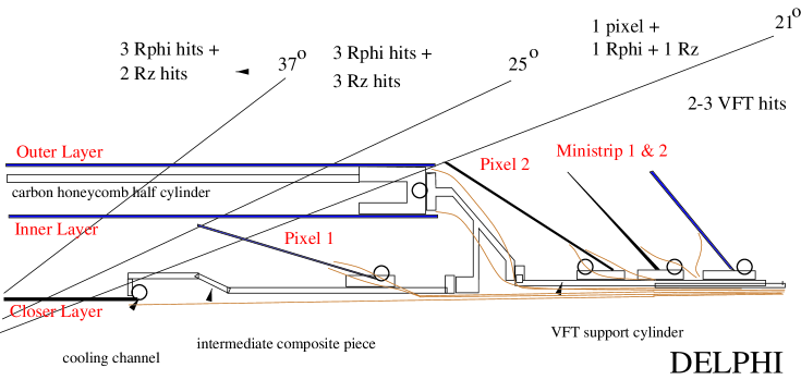
Figure 1 shows an cross section of a quarter of the DELPHI Silicon Tracker. A detailed description of the detector (in its final setup) can be found in [3]. It is divided into a barrel part (Vertex Detector, VD) and the VFT in the forward direction. For the installation around the beam pipe the mechanical structure is divided into two half shells in .

The VD consists of 3 concentric layers (called Closer, Inner and Outer) at average radii of 6.6 cm, 9.2 cm and 10.6 cm, respectively. All three layers cover polar angles of , the Inner layer extends the coverage to . The Closer as well as the Outer layer is made of 24 modules with a 15 % azimuthal overlap, while only 20 modules are used for the Inner layer (figure 2). Each module in the Outer and the Inner layer consists of 8 sensors, the Closer layer modules are shorter and consist of only 4 sensors. Half of each module is bonded in series and read out at the outer ends. All Closer and Outer layer modules have double sided readout to measure and , while only the ”extreme” 2 sensors in the Inner layer are double sided, the ”central” sensors measure only . The n-side lines of one sensor of the ”flipped” modules in the Closer and the Inner layer are connected to the p-side ones of the adjacent sensor.
The hit resolution in is m. In the plane the readout pitch is changed for plaquettes at different angles to give the best resolution perpendicular to the track, varying between m and m for tracks at different inclinations.
The VFT consists of two pixel layers, the first one being located inside the VD, and two mini strip layers. It covers the angular region of and . The pixel dimension is m2. The two layers of back-to-back mini strip detectors have a readout pitch of m and one intermediate strip. To help the pattern recognition the mini strip modules are mounted at a small stereo angle.

A detailed description of the DELPHI apparatus can be found in [4]. A schematic view of the detector is shown in figure 3. The DELPHI outer tracking system is divided into a barrel and a forward part.
In the barrel part precise tracking information is provided by the Time Projection Chamber (TPC) and the Inner (ID) and Outer (OD) Detectors. The ID consists of a jet chamber to perform a precise measurement and of 5 concentric layers of straw tubes. It is followed by the TPC, which covers polar angles between and . The TPC single point resolution for charged particles is m in and m in . The Outer Detector is mounted behind the Barrel RICH to give additional tracking information at a radius of m. The five layers of drift cells cover polar angles between and and provide and information.
In the forward region the tracking is improved by two planar drift chambers in front of and behind the Forward RICH. Their polar angle coverage is (FCA) and (FCB), respectively. The Forward RICH provides an additional track point from the ionisation of the charged particle inside the drift box.
3 Precision tracking in the barrel part
The detectors of the outer tracking system in the barrel region measure the tracks of charged particles with high redundancy. Local pattern recognition algorithms are used to reconstruct the track elements in the different detectors. The VD cluster reconstruction algorithm is documented in [6]. A careful treatment of the VD hit information and good simulation description are needed together with an optimised track reconstruction software in order to exploit the high precision tracking information in the barrel region.
3.1 Internal VD alignment
The internal alignment of the Silicon Tracker is based on a mechanical survey, during which the components and the whole structure were measured by optical or mechanical means. The survey was done in two steps [7]. First a measurement of each individual module was done to fix the position of a sensor within a module to a level of 1-2 m. Then the position of each module in the two half shells was determined with a relative precision of about 10 m.
The detector may significantly deform after the survey during transportation and installation. Therefore the final precision is obtained by an offline alignment using tracks from charged particles. The first step after the installation of the detector is the determination of the relative position of the half shells w.r.t. each other using charged tracks crossing the top or bottom overlaps of the two halves.
Several effects which influence the detector alignment are taken into account in the alignment procedure [8]. The Lorentz angle effect leads to a shift of m in ( Tesla). Due to the flipped module design the resulting shift for a reconstructed hit is opposite for sensors where the p-side is facing the beam pipe or the outer tracker. Moreover, in the study of the Lorentz angle effect it has been found out that the barycentre of the holes and electrons created by the charged particle passing through the detector does not correspond exactly to the mid-plane of the detector. A 10-20 m shift of the barycentre of holes and electrons in the radial position towards the p-side needs to be taken into account. Finally bowing of individual modules along of up to 150 m in radius has been observed. This effect is related to stress during installation and the size of the bowing varies with temperature and humidity.
The final alignment [9] is done using charged tracks in and hadronic events. The Outer layer (see figure 2) is taken as a master layer for the whole detector. Its modules are aligned w.r.t. each other using hadronic tracks passing the 15 % azimuthal overlap between adjacent modules. The Closer layer is aligned w.r.t. the Outer layer using muons in events, where the momentum of each muon track is fixed to the nominal value. The Inner layer is aligned to the other two using again tracks from hadronic events. This procedure is iterated a few times until a stable alignment is found. At the end an overall twist of the detector around the beam axis is measured [9] using the geometrically signed impact parameter of tracks w.r.t. the beam spot as a function of their polar angle .
3.2 Shaken VD alignment for the simulation
The intrinsic hit resolution of a VD sensor is 5 m, while in DELPHI a resolution of m [3] has been achieved. The difference reflects imperfections in the internal alignment and small deformations in the flatness of the sensors.
The simulation needs to reflect the actual precision obtained for the data. For example a simple hit smearing would not allow for correlations between tracks, because in real data tracks hitting the same sensors are affected in the same way by residual problems. Therefore a scheme of shaking the detector position in the reconstruction of simulated events is used to model the actual resolution. Such a scheme also includes effects of misalignment at the track reconstruction level into the simulation. The position of each sensor is varied from its nominal position on an event by event basis [6]. This is needed in order not to have any visible pattern in the misalignment of the simulation. Such a pattern would have been cured by the alignment procedure on the real data. The RMS of the shifts applied were e.g. 6.4 m in , 7.3 m in and 20 to 37 m in for the simulation corresponding to the 1995 real data. Typical rotations are of the order of 0.15 - 0.4 mrad.
3.3 Quality cuts on cluster signal over noise
It is necessary to remove noise clusters from the event to avoid tails in the impact parameter resolution function. Cuts on cluster signal over noise are applied to improve the purity of good hits without losing much efficiency. The VD is made of several different sensors which have different signal over noise performance. Typical values range from 10 to 18 and close to 30 for the p-side of the single metal Outer layer [3]. Hence the cuts on signal over noise are tuned for each module and vary from 6 to 15. The cuts are applied to the hits at association time and depend on the track topology to improve the efficiency.
Tracks having hits in 3 out of 3 layers are very tightly constrained and therefore the chance of picking up a random noise hit is very small. For such tracks it is required that only 2 out of 3 associated hits pass the signal over noise cut.
3.4 Efficiency correction for the Simulation
The description of the hit efficiency of the detector is an important aspect of the simulation. Dead modules and dead channels need to be taken into account too. A sensor by sensor tuning [6] of the hit efficiency is done in the simulation by randomly removing hits from the event in order to match the apparent efficiency to the one in the real data. Modules which are inefficient for only parts of the data taking period are allowed for by dropping the module information from a corresponding fraction of the simulated events.
3.5 Kalman Filter track fit
The task of the track fit is to determine the track parameters from the combination of VD hits and track elements measured in the outer tracking system. The track fit algorithm used by DELPHI is a Kalman Filter [10], which is a fast recursive algorithm. It is implemented using the weight matrix approach.
A Kalman Filter is an estimator for a linear system, while a track in a solenoid field is described by a helix. A Taylor expansion around the reference trajectory is used as a starting point to obtain a linear system. The fit is iterated to ensure good convergence.
The DELPHI track fit takes into account the effects of multiple scattering and energy loss of particles in the material. A simplified description of the detector material is sufficient for the purpose of track fitting. The geometry of the detector material of the outer tracker is approximated by a sequence of surfaces, which are either cylinders around or planes perpendicular to the beam pipe. For each of these surfaces an apparent thickness is specified in terms of radiation length and energy loss of a minimal ionising particle (for a particle crossing at ).
A different approach is used for the VD material in the fit. Multiple scattering and energy loss in the material of the VD and the beam pipe are dominant contributions to the impact parameter resolution. Therefore a more detailed description of the material distribution is used for the track extrapolation and fitting inside the VD. The description reflects the complicated support structures and the overlap of modules in the individual layers in the corresponding azimuthal regions as can be seen in figure 2.
In the track fit the effect of the multiple scattering is taken into account by increasing the error contour of the track extrapolation after crossing the material surface. The momentum dependent effect of the energy loss is taken into account by changing the curvature of the reference trajectory used for the Taylor expansion in the fit.
Another important feature of the DELPHI fit is the logic to remove outliers. The fit is able to remove up to 3 measurements from a track candidate if it fails a fit probability cut of 0.1 %. This is a very effective filter to remove wrong associations of hits to tracks. A ranking of detectors to be removed is used in order not to remove the most precise measurement (e.g. the TPC track element) from the track. Called from the track search packages the fit always retains the track element which was used as a starting point to reconstruct the track.
3.6 Optimised track search algorithms
The first version of a DELPHI track search [11] was based on the track elements found in the TPC. These track elements were extrapolated to the ID jet chamber and the OD to associate additional hits. The output of the searches was a sample of candidates. The track parameters for all of the candidates were determined by the track fit and bad combinations were removed. Remaining ambiguous associations were resolved by a two stage process selecting good tracks. No VD information was used to further constrain the ambiguity decision. The VD hits were associated afterwards. In a first step all tracks were extrapolated to the VD layers and the hits were associated track by track, in the second step the hits were associated. After the association all tracks were fitted to include the VD information in the track parameters. Any mistake done in the linear chain of reconstruction steps resulted in a problem for the following steps. This led to rather unstable results which furthermore were not reproduced in the simulation. The performance of the package was strongly dependent on the track density and therefore problems were more frequent in events with heavy quarks.
The new track reconstruction software is using a completely different approach. Now the VD is used as a starting point for the track search, because it is the most precise detector and has the best two track resolution of all tracking detectors in DELPHI. There are two new track search algorithms, one is using all combinations of TPC tracks and 2 or 3 associated hits in the VD [12], the other is starting with ID jet chamber hits plus VD hits [13]. The algorithms were designed in only without using VD hit information, because the Silicon Tracker had no double sided readout for half of the LEP 1 data taking period. In both new searches bad combinations are filtered using the track fit. Remaining candidates are extrapolated to the other detectors to search for possible associations of additional hits. Each association is tested again using the track fit outlier logic. All ambiguous track combinations are then fed into a new ambiguity processor to resolve the full event. This processor will be discussed later in this paper.
The new reconstruction software uses the VD hits, which are present for the last two years of LEP 1 data taking and for the complete LEP 2 data set, to improve the resolution. The hits are associated to the resolved tracks found using only the hit information. All possible associations of hits to tracks are considered and filtered using the full track fit. The ambiguities are then resolved in a second run of the global event ambiguity processor.
3.6.1 Secondary interactions in material
Searches for vertices from hadronic interactions, from conversions and from decays of and are part of the new tracking software [14]. Figure 4 shows an example of a hadronic interaction in the detector material in front of the TPC. The TPC track elements of secondary particles produced due to such interactions or decays are a problem for the track reconstruction, because wrong association of VD hits to secondary tracks would disturb the correct association of VD hits to primary tracks.
Therefore the vertex searches are called before the track searches to reconstruct such secondary vertices using only the TPC track elements. All track elements associated to the secondary vertices are removed from the event before the full reconstruction of primary tracks. No VD hits are associated to these TPC track elements. A dedicated track search is then performed to reconstruct the tracks which are pointing to the hadronic interaction vertices [13, 15]. This search uses the remaining unassociated hits in the VD and the ID jet chamber after the reconstruction of primary tracks which did not cause a hadronic shower before the TPC. The tracks measured only in the VD or the VD and the ID jet chamber are then linked [14] to the secondary vertices to fully reconstruct the track-vertex structure. Finally elastic interactions and decays in flight of pions or kaons are reconstructed.
3.7 The concept of ”exclusions”
The result of track searches is a set of ambiguous track candidates with many possible associations of individual hits to different track candidates. Also the local pattern recognition of the different detectors can create ambiguous hit combinations. For example in the VFT mini strip detector space points are reconstructed out of hits on the back-to-back module by combining the measurements in both orientations so that hits from tracks on a module lead to mirror images. In the ID jet chamber the left/right ambiguity can not be resolved using only the detector information itself. All such ambiguities need to be resolved in the process of the track reconstruction. It is beneficial to leave the decisions to the stage of the global event solution, since at this stage the full information of the reconstructed track candidates can be used to minimise mistakes.
All results from the different reconstruction packages are stored in the DELPHI event database [16]. The database structure allows for so called ”logical exclusions” between objects like hits or track candidates. An ”exclusion” signals that two objects use conflicting or common detector information and that for the final solution of the event such conflicts need to be resolved.
3.8 Event ambiguity processing
The ambiguity solution is a combinatorial problem. The task of the ambiguity processor is to decide about the association of (VD) hits and to select the best tracks out of the set of mutually ”excluded” candidates found by the search algorithms. The design of the DELPHI ambiguity processor [17] was done in order to find a balance between performance and CPU consumption.
The ambiguity processor maximises a ”score” function for a given event. The score of each track in the solution is determined by the number of hits associated to the track and the quality of the fit. A simple algorithm to resolve the event can start by selecting the track with the highest score. The hits associated to that track are removed from all other candidates. This implies refitting the candidates from which a hit has been dropped. The list of candidates is therefore changing in the course of the process. The process is iterated by selecting the next best track until no more candidates are left over. This algorithm is very fast, but any mistake at the beginning propagates through the rest of the event analysis. Another algorithm, which does not have this problem, would be to create all possible lists of tracks, which contain no ”exclusions” anymore, in the same way as before. Here the list with the highest score would be selected. This algorithm is limited by combinatorics, because the number of lists increases very rapidly with the number of candidates.
The DELPHI ambiguity processor is a mixture of both algorithms. It is a recursive algorithm, which in each step subdivides the event into sets of ”excluded” tracks to resolve them independently. For each set all possible lists of tracks are tried. One track after the other is taken out of the set and each time the subset is resolved in the next recursion level. For each recursion the maximum possible score of the subset is calculated to truncate combinations below the current maximum. A fall back solution is implemented, which uses the simpler algorithm for a set in case it is not resolved after more than 2 minutes or the recursion depth is exceeding 9 levels.
Additional protections are needed. Sub-tracks created during the processing are rejected if they are only generated by splitting a long track. A list of bad tracks is used to reject detector combinations of poor quality or high risk of being fake.
The scoring function is tuned to optimise the track reconstruction efficiency and the hit association purity at the same time. For each track a score of 100 is assigned, while a detector measurement associated to the track is given a score between 1 and 20, depending on the quality of the measurement, and a logarithm of the probability of the track fit is added to disfavour bad track candidates.
The ambiguity processor is used three times in the track reconstruction code. It is called for the first time to resolve the tracks including the VD hits, a second time to resolve the association of the hits and finally to resolve ambiguities in the search dedicated to reconstruct tracks before interactions with the material.
3.9 Results of the new barrel track reconstruction package
The new central tracking has been successfully used for the final reprocessing of the full LEP 1 data set and for the processing of the LEP 2 data. An excellent reconstruction quality has been achieved and the precision of many DELPHI physics results has been improved.
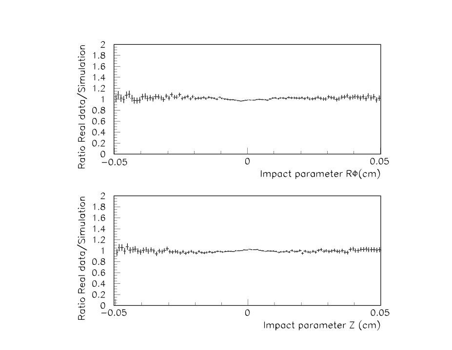
The impact parameter resolution for charged tracks from hadronic events has been measured [3] to be :
| (1) | |||||
| (2) |
In both cases the first term, which depends on the track polar angle , is the contribution due to multiple scattering, the second term is the asymptotic value reflecting the measurement error. The average miss distance at the interaction point between the two muons in events is measured to be 33 m in and 51.6 m in [18]. In figure 5 the ratio of the impact parameter distributions of reconstructed tracks from hadronic events in real data and simulation are shown separately for and . The resolutions are correctly described and the tails in the distributions due to wrong association of VD hits to tracks are reproduced in the simulation.
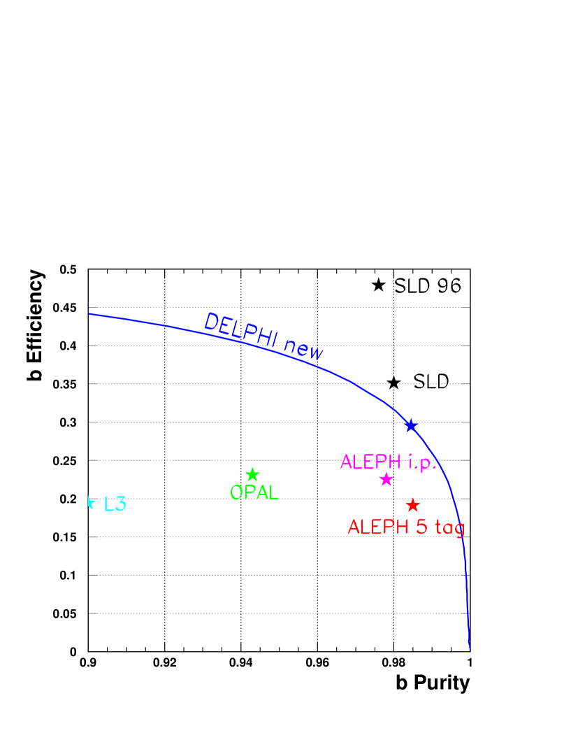
The most dramatic improvement due to the new reconstruction algorithms is visible in the -tagging performance [19]. The average number of tracks per hadronic decay used to determine the content increased from 9.5 to 14.3. Figure 6 shows a comparison of the -tagging efficiency as a function of purity for different experiments. After the reprocessing DELPHI outperforms all other LEP experiments. Only SLD has a better resolution due to its smaller beam pipe and the smaller dimensions of the beam spot.
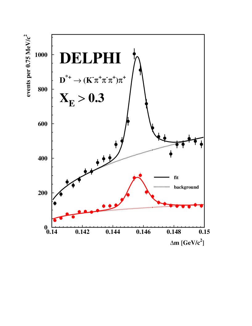
Figure 7 shows the mass difference between the and the from the decay , where the decays into . The signal is shown for both processings using the old and the new track reconstruction code. In both cases the decays are reconstructed using the same analysis code and the same set of cuts. A gain of a factor 2.5 in efficiency is observed for such complicated decay modes.
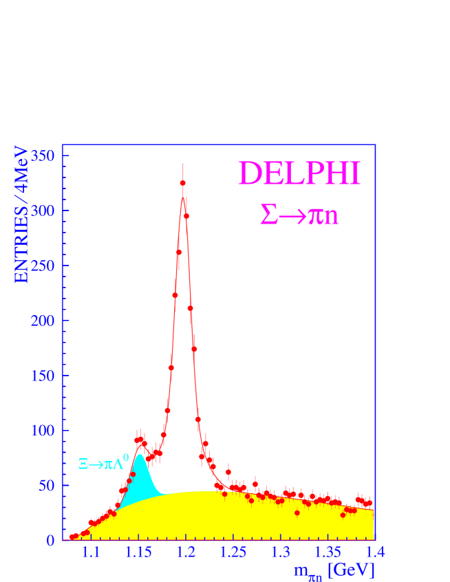
An example of an application [20] of the secondary vertex search is shown in figure 8. The mass signal of decays is reconstructed from the tracks measured in the VD and the tracks of the decay pions. The vertices have been found by the search for decays in flight.
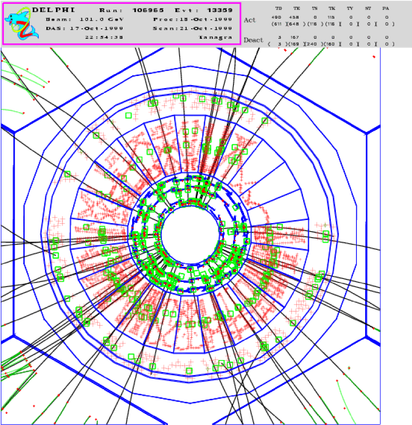
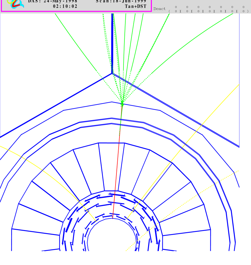
Figure 9 shows an example of a reconstructed high multiplicity multi-jet event taken at an centre-of-mass energy of 202 GeV in the year 1999. No significant degradation of the -tagging resolution has been observed for such complicated events.
4 VFT standalone tracking and the acceptance in the forward region
In contrast to the barrel tracking the track reconstruction strategy in the forward region is completely different. In this region the VFT is needed to improve the acceptance for charged particles. Standalone track reconstruction in the VFT is mandatory to measure the tracks before most of the particles shower in the material of the end rings of the barrel detectors.
4.1 VFT standalone track reconstruction
The VFT (see figure 1) consists of two layers of pixel detectors and two layers of back-to-back mini strip detectors. It gives on average 2 to 3 space points per track in the polar angle range from to . An important aspect of the pixel detector is the low random noise rate of after an offline suppression of 0.3 % of systematically noisy pixels [3]. This ensures a small rate of fake hits and consequently a good purity in the reconstruction. The reconstructed clusters in both views of a back-to-back mini strip module are combined to obtain 3 dimensional hit information.
The standalone tracking [3] is done in 3 steps. First all combinations of 3 layers are tested and the track parameters are determined using a helix fit. One requires the reconstructed track elements to point towards the primary interaction region. The primary interaction region has a dimension of 0.77 m in and of 150 and 10 m in and , respectively [21]. In the next step the track finding efficiency is improved using all left over two hit combinations in both pixel layers. The point of the average primary interaction position is added to the combinations to determine the track parameters. Finally a similar strategy is used for combinations of space points in both mini strip layers. A stereo angle and flipping of the module orientation leads to a relative angle of between the strips in the same projection of both layers. This relative angle is used to remove fake combinations of mirror images which do no longer point towards the primary interaction region. The result of the standalone tracking as well as all hits are then used in the forward search to reconstruct the full track.
4.2 The VFT in the forward track search
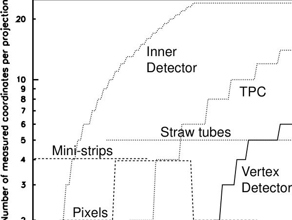
The forward track reconstruction [22] is limited by the material of the end rings of the barrel detectors, which amounts to 1.4 radiation length in front of the electromagnetic calorimeter. Furthermore tracks are dropping out of the acceptance of the central detectors with decreasing polar angle as it is shown in figure 10, where the number of measurements can be seen as a function of polar angle for all detectors but the forward chambers. The latter contribute 18 additional points over the full range, but they operate behind the material of the end rings of the barrel detectors.
The VFT, which is close to the interaction region, is the basis of the track forward finding. The track search algorithm uses as starting points as many different seeds as possible. These seeds are either VFT tracks from the standalone tracking, combinations of VFT hits with ID jet chamber hits or other detector combinations like VD and ID jet chamber or TPC. In total 12 different combinations are tried. Starting from each of the seeds a simple road search is done to look for possible hits in the other detectors to be associated to the track candidate. On the resulting list of all possible hits from all detectors a search is done for track combinations including the maximum number of detectors. The Kalman Filter track fit with its outlier logic serves as the final filter to select good candidates, which are fed into the global event solution to resolve ambiguities. At this stage of the reconstruction no tracks measured only in the VFT and in the VFT and the ID jet chamber are considered. A dedicated search is done afterwards to reconstruct these tracks out of the remaining tracks found by the VFT standalone track reconstruction.
4.3 Results of the new forward tracking

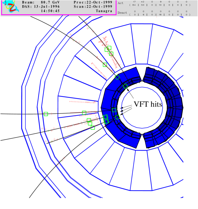
Figure 11 shows the improvement of the track finding efficiency for primary tracks from the interaction region as a function of the polar angle after including the VFT into the forward track reconstruction. A clear gain is visible down to for tracks reconstructed using the VFT. Below the ID jet chamber drops out of the tracking and the VFT standalone tracks are used to extend the efficiency plateau down to . An example of a event is shown in figure 12. In the event one electron is measured in the Small Angle Tile Calorimeter. Most of the tracks are reconstructed using the VFT hit information.
5 Conclusion
The DELPHI Silicon Tracker is used successfully in two different tracking situations. In the barrel region the VD provides precision tracking information. Optimised algorithms were developed to reconstruct the charged tracks starting from the VD hits. The result of this new reconstruction software is an excellent data quality which gives DELPHI the best -tagging performance of all LEP experiments. In the forward region different reconstruction strategies based on the VFT are used to significantly improve the track reconstruction efficiency down to a polar angle of .
Acknowledgements
I would like to thank P. Bruckman, K. Österberg, M.E. Pol and C. Weiser for providing me with material for the presentation. I also like to thank K. Österberg for reading the article and sending constructive comments.
References
- [1] N. Bingefors et al., Nucl. Instr. and Meth. A 328 (1993) 447.
- [2] V. Chabaud et al., Nucl. Instr. and Meth. A 368 (1996) 314.
- [3] P. Chochula et al., Nucl. Instr. and Meth. A 412 (1998) 304.
-
[4]
A. Aarnio et al., DELPHI Collaboration, Nucl. Instr. and Meth. A 326
(1991) 233,
P. Abreu et al., DELPHI Collaboration, Nucl. Instr. and Meth. A 378 (1996) 57. - [5] A. Olchevski, Precision Tests of the Standard Model, Proceedings of the International Europhysics Conference on High Energy Physics, Brussels 1995.
- [6] K. Österberg, PhD thesis HIP-1998-01, Department of Physics, University of Helsinki, 1998.
- [7] A. Andreazza et al., Nucl. Instr. and Meth. A 312 (1992) 431.
- [8] V. Chabaud, Parametrising detector specific effects for the Barrel of the DELPHI Silicon Tracker, DELPHI 98-161 MVX 25, Geneva 1998.
- [9] V. Chabaud, A. Andreazza, P. Collins, H. Dijkstra, Alignment of the DELPHI Vertex Detector, DELPHI 95-177 MVX 10, Geneva 1995.
-
[10]
R. Frühwirth, Nucl. Intr. and Meth. A 262 (1987) 444;
P. Billoir, Nucl. Intr. and Meth. 225 (1984) 352. - [11] DELPHI Collaboration, DELPHI Data Analysis Program (DELANA) User’s Guide, DELPHI 89-44 PROG 137 , Geneva 1989.
- [12] R. McNulty, private communication.
- [13] M. Blume, G. Sciolla, M. Caccia, Study of a combined ID-VD pattern recognition, DELPHI 95-18 PROG 212, Geneva 1995.
-
[14]
P. Abreu et al., DELPHI Collaboration,
Nucl. Instr. and Meth. A 378 (1996) 57;
M. Feindt, W. Oberschulte gen. Beckmann, C. Weiser, How to use the MAMMOTH program, DELPHI 96-52 PROG 216, Geneva 1996;
M. Feindt, C. Kreuter and O. Podobrin, ELEPHANT Reference Manual, DELPHI 96-82 PROG 217, Geneva 1996. - [15] M. Elsing, The new ID+VD track search in DELANA, DELPHI note in preparation.
- [16] D. Bertrand, L. Pape, TANAGRA : Track Analysis and Graphics Package DELPHI 86-75 PROG 55, Geneva 1986.
- [17] D. Wicke, A New Algorithm for Solving Tracking Ambiguities, DELPHI 98-163 PROG 236 TRACK 92, Geneva 1998.
- [18] P. Bruckman, private communication.
- [19] P. Abreu et al., DELPHI Collaboration, A precise measurement of the partial decay width ratio , CERN/EP 98-180, Geneva 1999, to be pubished in E. Phys. J. C.
- [20] C. Weiser, Messung der Produktionsraten von , und Hadronen in -Zerfällen, IEKP-KA/98-5, Karlsruhe 1998.
- [21] W.J. Murray, DELPHI Collaboration, Measurement of the beam position in DELPHI, DELPHI 96-6 PHYS 590, Geneva 1996.
- [22] M. Elsing, Summary of the updates in the DELPHI forward tracking to include the VFT, DELPHI 98-5 PROG 227 TRACK 91, Geneva 1998.