Pendulum Mode Thermal Noise in Advanced Interferometers: A comparison of Fused Silica Fibers and Ribbons in the Presence of Surface Loss
The use of fused-silica ribbons as suspensions in gravitational
wave interferometers can result in significant improvements in
pendulum mode thermal noise. Surface loss sets a lower bound to
the level of noise achievable, at what level depends on the
dissipation depth and other physical parameters. For LIGO II, the
high breaking strength of pristine fused silica filaments, the
correct choice of ribbon aspect ratio (to minimize thermoelastic
damping), and low dissipation depth combined with the other
achievable parameters can reduce the pendulum mode thermal noise
in a ribbon suspension well below the radiation pressure noise.
Despite producing higher levels of pendulum mode thermal noise,
cylindrical fiber suspensions provide an acceptable alternative
for LIGO II, should unforeseen problems with ribbon suspensions
arise.
PACS - 04.80.Nn, 95.55.Ym, 05.40.Ca
I Introduction
One of the most important limitations to the sensitivity of long baseline gravitational wave detectors such as LIGO [1], VIRGO [2], GEO 600 [3],and TAMA [4] is thermal noise associated with the test masses and their suspensions. Designs for advanced detectors propose either fused silica or sapphire test-masses. For fused silica test-masses internal mode thermal noise is expected to be an important source of noise from approximately 20 Hz to a few hundred Hertz, whereas pendulum mode thermal noise is more important below this range.
Pendulum mode thermal noise is due primarily to dissipation in the suspending filaments. It is imperative, therefore, to minimize the intrinsic losses in the filament. Many current detector designs use metal wires to suspend the test-mass, but metals, with , result in unacceptably high levels of pendulum mode thermal noise. Fused silica has lower loss () and monolithic fused silica suspensions have been shown to have much higher than metal wire suspensions [5, 6, 7]. Such a monolithic suspension system is being developed and adopted for use in the GEO 600 detector [8], while variations of this design are being considered for LIGO II. In particular, fibers with circular cross sections may be replaced with fused silica ribbons [8, 9, 10], which allow the suspension filaments to be very thin and compliant in the direction of motion [11, 12, 13].
Experiments indicate that in thin fused silica filaments much of the dissipation takes place in a layer near the surface [7]. The level at which surface loss affects the total pendulum mode dissipation depends on the filament thickness and geometry, and influences the choice of suspension design parameters. To investigate this, we calculate the pendulum mode thermal noise, including surface dependent loss, as a function of the design parameters for fibers and for ribbons.
II Dissipation Dilution
In the absence of external sources of dissipation, the dissipation in the fundamental mode of a pendulum suspended by a filament is given by[14]
| (1) |
where is the loss angle of the unloaded suspension filament, is the Young’s modulus of the filament material, is the cross-sectional moment of inertia, is the supported mass, is the acceleration due to gravity, and is the filament length. In general, and hence will be a function of frequency. The coefficient of is called the dissipation dilution factor and is the ratio of elastic energy (subject to dissipation) to the total energy stored in the pendulum mode, which is predominantly gravitational energy (non-dissipative). The right hand side of this equation should be multiplied by two if the mass is constrained from rotating in the plane of oscillation, since bending then occurs both in the region where the filament leaves the support and in the region where the filament leaves the mass. If the test mass is suspended by filaments Eq. 1 should be multiplied by . For fibers of diameter , and ribbons of thickness and width , we have
| (2) |
where subscripts refer to fibers and subscripts to ribbons. Rewriting Eq. 1 using these expressions for the cross-sectional moment of inertia, allowing multiple filaments and assuming that the suspension constrains the filaments to bend at both ends, we have
| (3) |
where is the suspended mass, is the number of suspension fibers, is the loss angle of the unloaded fibers, is the number of suspension ribbons, and is the loss angle of the unloaded ribbons. The limit to how much dissipation dilution we can obtain, and hence the lower limit to the pendulum mode thermal noise, is set by the values obtainable for the parameters in these equations. They are limited by a number of material and technological concerns, especially by the value achievable for the loss angle or . This loss angle may depend on a number of factors including the bulk material loss angle, surface loss, and the filament geometry.
If and were independent of filament thickness and roughly equal, Eq. 3 would indicate that by using very thin but wide ribbons one could obtain lower dissipation , and hence less pendulum mode thermal noise, than by using fibers of similar load bearing capacity. However, since surface loss becomes increasingly important as the filament thickness is reduced, the enhanced dissipation dilution obtainable using thin ribbons is moderated by an increase in .
III Thermal Noise in the Presence of Surface Loss
The loss angle for a sample, including surface loss, may be expressed as[7]
| (4) |
where is the loss angle of the bulk material, is a geometrical factor and is the dissipation depth which parametrizes the filament size at which surface loss becomes important. The geometrical factor describes the emphasis placed on the condition of the surface due to the sample geometry and mode of oscillation while the dissipation depth describes the amount of surface damage and the depth to which it penetrates. Equation 4 serves to define , whose value for a given sample may be determined by experiment. The geometrical factor is given by
| (5) |
where denotes a point in the sample, the strain amplitude, is the volume of the sample, the surface area of the sample, is the set of points comprising the volume, and is the set of points comprising the outer surface. For transverse oscillations of fibers and ribbons we have
| (6) |
where is the aspect ratio of the combined ribbons, with being the total combined width of the ribbons.
Experiments suggest that is approximately constant over the frequency range of interest for LIGO[6, 7, 23]. For simplicity, we will assume to be constant. Substituting Eqs. 4 and 6 into Eq. 3 we obtain
| (7) |
where is the filament stress. In both cases, the first term is the traditional expression for dissipation dilution, while the term involving represents a reduction of the dilution due to the increasing importance of surface loss as the filament thickness is decreased. For very thin filaments the term involving dominates and the loss angle becomes independent of the filament thickness.
From the fluctuation-dissipation theorem [15], we find the power spectrum of the pendulum mode thermal fluctuations above the pendulum mode resonance, at angular frequency :
| (8) |
where , is the temperature of the suspending filaments and is the radius of the arc traced out by the center of mass during pendulum mode oscillation. For convenience, we will take . Inserting from Eq. 7, and including the contribution from thermoelastic damping we have the expression for the pendulum mode thermal noise:
| (9) |
The thermoelastic damping term is given by[16]
| (10) |
where is the thermal expansion coefficient of the filament material, is the heat capacity per unit volume, and is the thermal diffusion coefficient.
IV Advanced Interferometers
Using Eq. 9, we can now make estimates for the level of pendulum mode thermal noise achievable in advanced interferometers and investigate the dependence on filament thickness and geometry. Using the results of previous experiments and design studies, most of the parameters can be well bounded with some reasonable assumptions. From these parameters, we can obtain upper and lower bounds on the pendulum mode thermal noise at a given frequency as a function of ribbon thickness. This analysis assumes that losses extrinsic to the filaments (e.g. recoil of the suspending structure or lossy filament-to-test-mass bonds) have been made negligible.
The achievable fiber diameter depends on the achievable stress and on the mass . The fiber diameter in Eq. 9 can be replaced by
| (11) |
The remaining parameters ,,, , and are independent and the achievable pendulum mode thermal noise depends on the bounds established for these parameters.
It is clear from Eq. 9 that an efficient way of minimizing the thermal noise is to make the length of the suspension as large as possible. However, the value of is bounded above by the minimum allowable spacing of the violin mode frequencies. The frequency spacing must be kept above about 300 Hz to allow reasonably large intervals of the spectrum to be free of violin modes. The frequency spacing limited is
| (12) |
where is the minimum allowable spacing of the violin modes. The range of possible lengths is determined by the range of possible stress to which the filaments will be subject. This in turn depends on the breaking strengths achievable for fused silica filaments. Many measurements have been reported on the breaking strength of fibers manufactured from naturally occurring, and synthetic, vitreous silica[17, 18]. Little is known about the strength of ribbons, though one is tempted to assume their strengths are similar. Values reported for the breaking strength of fibers in tension at room temperature vary greatly depending on the condition of the fibers [19], but strengths on the order of several gigapascals at room temperature, in fibers with diameters as large as 1 mm have been reported [20, 21, 22]. By assuming that the filaments are only loaded to a fraction of their breaking strength we assign the range of possible stress to which the filaments will be subject as . Substituting these values into Eq. 12 we obtain the range of possible lengths . In principle, the physical design of the suspension also places an upper limit on the length, but ultimately this limit is likely to be less stringent than that due to the frequency spacing.
For the number of filaments we will choose . This reflects the most likely choice for the suspensions in advanced detectors which require “marionette” control of the test masses [10]. Analytically, the number of ribbons does not enter into the calculation as, for a given stress and ribbon thickness , only the total combined width of the ribbons is fixed.
In order to avoid excessive radiation pressure noise in LIGO II, the suspended test masses must have a mass of 30 kg. However, if this is not feasible, the LIGO I mass of 10 kg can be used as a fall-back. We take 10 kg 100 kg to allow for possible advanced designs that utilize even larger masses [10].
For the bulk material dissipation in fused silica, Gretarsson and Harry have measured [7]. Others have measured similar values for the bulk material dissipation in samples of different geometry [6, 23, 24, 25]. We shall adopt the relatively reliable upper limit and somewhat uncertainly set the lower limit as
Finally, for untreated fused silica fibers drawn in a natural gas flame, m has been measured [7]. It should be noted that the factors resulting in a given quality of fiber surface are not well quantified. Fibers pulled from silica rods with different initial surface conditions, or fibers drawn using a different production method, may have a different dissipation depth or surface loss than that found in the measurements above. The geometry of a filament could also have some effect on the quality of the surface layer, e.g. through different cooling stresses during fabrication, and our assumption that fused silica ribbons have the same surface properties as fused silica fibers has not been tested. However, given these assumptions we set an upper bound of m, which should be reliable. To estimate a lower bound for we will use a -measurement of a ribbon of thickness m, made of natural fused quartz [8]. One mode of this ribbon showed a much higher than others. After subtracting the loss due to thermoelastic damping (Eq. 10) and assuming the remaining loss is mainly surface loss, the equivalent for a similarly limited fused silica ribbon can be estimated at m. We, therefore, set the range of possible dissipation depths at 30 mm.
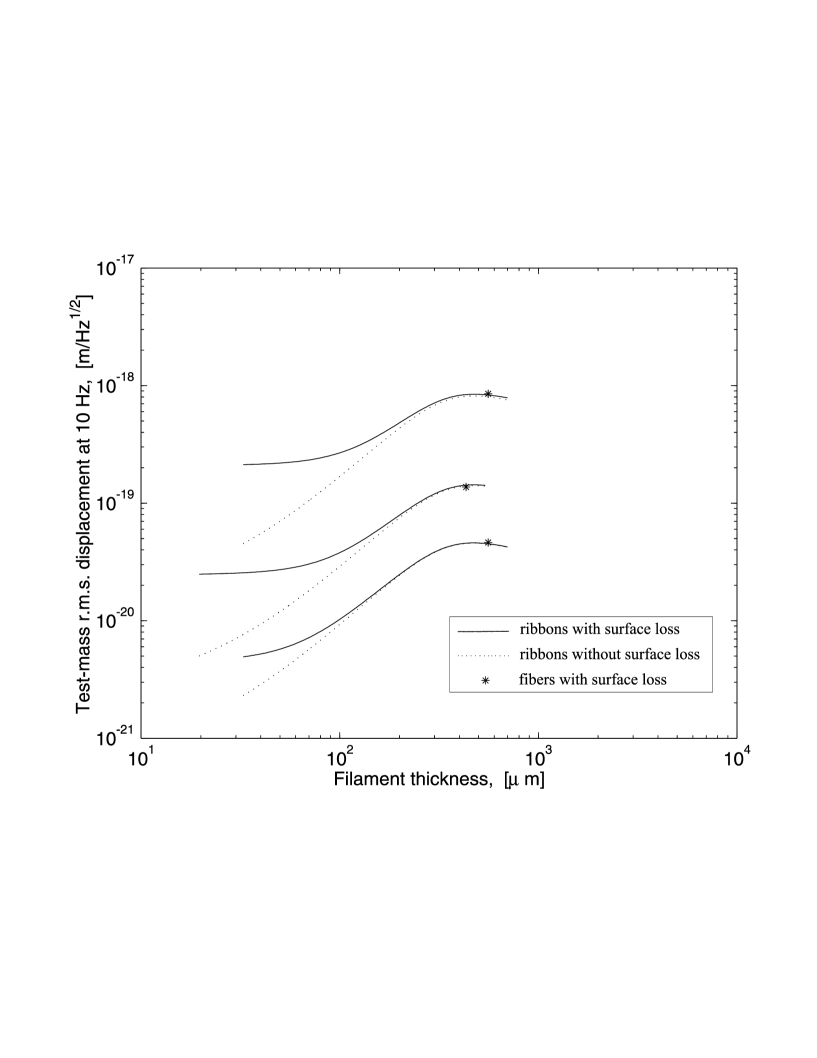
Table I summarizes the best and worst case estimates for the parameters, and also a “best guess” for the most probable values. Figure 1 shows the levels of pendulum mode thermal noise at 10 Hz as a function of filament thickness for each of the three sets of estimates of the parameters. The graphs for ribbon filaments all show a maximum around m. This is the thermoelastic damping peak, which for all but the most optimistic case must be avoided if the desired levels of pendulum mode thermal noise are to be achieved. Figure 1 also shows the value of using ribbons rather than fibers as suspension filaments. Since the diameter of fibers cannot be independently reduced, the pendulum mode thermal noise is dominated by thermoelastic damping. The use of ribbons allows us to evade this problem by residing in the surface loss limited regime. To evade the thermoelastic regime and to obtain better dissipation dilution one might be tempted to use the thinnest ribbons possible. However, at small thicknesses, below the thermoelastic peak, the graphs begin to level off. This is due to surface loss which sets a minimum to achievable pendulum mode thermal noise of
| (13) |
It is clear from the plots that, for all but the most optimistic values of , reducing the ribbon thickness below about m (corresponding to individual ribbon widths of 5 mm, 3 mm, and 5 mm for the three cases) does not result in significant reductions of pendulum mode thermal noise. To satisfy LIGO II requirements, the pendulum mode thermal noise at 10 Hz should be less than about [10]. Even in the presence of surface loss, only the worst case scenario does not achieve this level. In the most probable case, pendulum mode thermal noise will be lower than other noise sources at 10 Hz (radiation pressure noise, fused silica internal mode thermal noise), provided the ribbon thickness is kept below the thermoelastic regime. In the most optimistic case, other noise sources dominate the total noise at 10 Hz regardless of ribbon thickness. The most probable estimate for fiber suspensions gives pendulum mode thermal noise that is just acceptable for LIGO II. If there are unforeseen problems with ribbon suspensions, fiber suspensions may still prove an acceptable alternative. We reiterate that in the comparison of fibers and ribbons, we have assumed that the breaking strength of fibers is not significantly greater than that of ribbons of equal cross-sectional area; we have also assigned them identical surface properties. Further research is required to test these assumptions. Research is continuing on ribbon suspensions within the LIGO research community, and additional emphasis on surface properties and breaking strength is warranted.
V Comparison of low frequency noise sources in LIGO II
While studying the pendulum mode thermal noise at 10 Hz is a good way to gain insight into the effect of the different physical parameters on the level of this source of noise, the comparison with other sources of noise must be done over the entire range of relevant frequencies.
For clarity, we now specialize to a single set of values for the physical parameters of the suspension filaments–those proposed for LIGO II [10]. These parameters are shown in the last column of Table I. With a four ribbon suspension, it follows from the proposed stress that each ribbon should have a cross-sectional area of , giving a width of 5.5 mm for the m ribbon thickness proposed. In general, the values for all these parameters fall between the worst case and most probable case scenarios. As such, the LIGO II proposal is fairly conservative, and better noise performance may be achieved.
The LIGO II proposal does not, however, specify a value for . In keeping with the conservative spirit of the other parameters, we choose m. This falls between the worst case and most probable case and corresponds to the measured value in fibers without strict handling requirements [7].
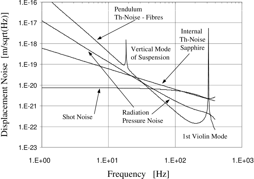
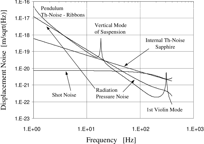
Figure 2 shows the pendulum mode thermal noise of a fiber suspension in relation to estimates for the other sources of noise in the interferometer. Figure 3 shows the same comparison for the pendulum mode thermal noise of a ribbon suspension [26]. Note that the noise due to radiation pressure in the LIGO II design is greater than the pendulum mode thermal noise for the ribbon suspension. For greater low frequency sensitivity, radiation pressure can always be reduced by lowering the amount of laser power at the beam splitter. This could reduce the noise to the pendulum mode thermal noise level in the low frequency band but will increase the amount of laser shot noise at higher frequencies. From figures 2 and 3 it is clear that while a ribbon suspension leads to lower pendulum mode thermal noise than a fiber suspension, the pendulum mode thermal noise for the fiber suspension is still comparable to radiation pressure noise in the relevant frequency band. If there are unforeseen problems with ribbons (buckling, lower strength, etc.), fibers do provide an acceptable, if less attractive, alternative.
VI Acknowledgments
We would like to thank our colleagues at the University of Glasgow, at Stanford University, and throughout the gravitational wave community for their interest in this work. Additional thanks to Ken Strain for his help with LIGO II parameters beyond the white paper as well as Gabriela Gonzalez, Gary Sanders, David Tanner, and Rai Weiss for their comments. This work was supported by Syracuse University, U.S. National Science Foundation Grants No. PHY-9602157 and No. PHY-9630172, the University of Glasgow, and PPARC.
REFERENCES
- [1] A. Abramovici et al, Science, 256 325 (1992)
- [2] A. Giazotto et al., Nucl. Instrum. Methods A 289, 518 (1988).
- [3] K. Danzmann et al., GEO 600: Proposal for a 600 m laser interferometric gravitational wave antenna, Max-Planck-Institut für Quantenoptik Report 190, Garching Germany (1994).
- [4] K. Tsubono, in Gravitational Wave Experiments, proceedings of the First Edoardo Amaldi Conference, World Scientific, 112, (1995).
- [5] V. B. Braginsky, V. P. Mitrofanov, and K. V. Tokmakov, Phys. Dokl. 40 564 (1995), Transl. from Dokl. Akad. Nauk, 345 324 (1995).
- [6] M. N. Danchevskaya, B. S. Lunin, and I. V. Batov, VIIth All-Union Scientific-Technical Conference on Fused Silica, Reports, St. Petersburg, Nov. 19-20, 1991.
- [7] A. M. Gretarsson and G. M. Harry, Rev. Sci. Instr., 70, 4081 (1999).
- [8] S. Rowan, R. Hutchins, A. McLaren, N. A. Robertson, S. M. Twyford, and J. Hough, Phys. Lett. A, 227 153 (1997).
- [9] J. E. Logan, J. Hough, N. A. Robertson, K. Danzmann and R. Hutchins, proceedings of the Seventh Marcel Grossmann Meeting, July 24-30, 1994 Stanford University, World Scientific.
- [10] LSC White Paper on Detector Research and Development. Available at http://www.ligo.caltech.edu/docs/T/T990080-00.pdf
- [11] R. Weiss, Quarterly Progress Report, MIT Research Laboratory of Electronics, vol. 105 (1972).
- [12] W. Martin, Ph.D. thesis, University of Glagow, Glasgow, United Kingdom, 1978.
- [13] D. G. Blair, L. Ju and M. Notcutt, Rev. Sci. Instrum. 64, 1899 (1993).
- [14] P. R. Saulson, Phys. Rev. D, 42 2437 (1990)
- [15] H. B. Callen and T. A. Welton, Phys. Rev. 83 35 (1951); H. B. Callen and R. F. Greene, ibid. 86 703 (1952).
- [16] C. Zener, Phys. Rev. 52 230 (1937).
- [17] O. V. Mazurin, M. V. Streltsina, and T. P. Shvaiko-Shvaikovskaya, Handbook of Glass Data, Part A, Silica Glass and Binary Silicate Glasses, Eslevier (1983), pp. 117-126, and references therein.
- [18] B. A. Proctor, I. Whitney, and J. W. Johnson, Proc. Roy. Soc. Sec. A, 297 534 (1967), and references therein.
- [19] F. M. Ernsberger, Strength and Strengthening of Glass, in Research Into Glass, Vol. 2, Glass Research Center, PPG Industries, Pittsburgh, 1970.
- [20] W. B. Hillig, J. Appl. Phys. 32 741 (1961).
- [21] J. G. Morley, P. A. Andrews, and J. Whitney, Phys. Chem. Glasses, 5 1 (1964).
- [22] N. A. Robertson et al., proceedings of the Third Edoardo Amaldi Conference on Gravitational Waves, July 12-16, 1999 California Institute of Technology, to be published.
- [23] W. J. Startin, M. A. Beilby, and P. R. Saulson, Rev. Sci. Instr. 69 3681 (1998)
- [24] E. J. Loper, D. D. Lynch, and K. M. Stevenson, IEEE PLANS (Position Location and Navigation Symposium) Record, Caesar’s Palace, Las Vegas, Nevada, November 4-7, 1986, pp. 61-64, Table 2.
- [25] G. Cagnoli, Presentation at LIGO Scientific Collaboration Meeting, Gainesville, Florida, March 1999.
- [26] The estimate of test mass internal thermal noise shown in Figs. 2 and 3 is based on the thermoelastic damping model of Braginsky et al. [27], including the correction for the finite mass size as in Liu and Thorne [28], for 32 kg sapphire masses of diameter 32 cm and beam radius 5 cm, and represents a likely value achievable for LIGO II [29]. To improve the interferometer sensitivity in the presence of thermoelastic damping in the test mass we have made a slight modification of the output optics parameters from the choices given in the LIGO II white paper [29].
- [27] V. B. Braginsky, M. L. Gorodetsky, and S. P. Vyatchanin, Phys. Lett. A 264 1 (1999).
- [28] Y. T. Liu and K. S. Thorne, submitted to Phys. Rev. D Feb. 15, 2000, gr-qc/0002055.
- [29] K. Strain, private communication.
| worst case | most probable | best case | LIGO II proposal | |
|---|---|---|---|---|
| m | m | m | m∗ | |
| 0.1 GPa | 0.5 GPa | 1.0 GPa | 0.13 GPa | |
| 10 kg | 30 kg | 100 kg | 30 kg | |
| 0.35 m | 0.79 m | 1.1 m | 0.39 m |
∗not specified in proposal