SPHERES – OMNI-DIRECTIONAL MULTI-MODE GRAVITATIONAL-WAVE ANTENNAS FOR THE NEXT GENERATION
Abstract
The sensitivity of resonant-mass gravitational-wave antennas has now reached , where is the dimensionless metric perturbation caused by the wave. In order to observe gravitational wave events such as coalescing neutron star binaries and colliding black holes from as far as the Virgo cluster of galaxies, the detector sensitivity must be improved by three orders of magnitude. With such an aim, construction of massive ( ton) spherical antennas have been proposed by a number of groups world wide. The standard quantum limit of the sensitivity of such detectors will be . Unlike a cylinder, a sphere has five degenerate quadrupole modes which interact with an incoming gravitational wave. By combining the responses of all these modes, one can determine the direction of the source and the polarization of the wave with a single spherical antenna. Summed over the modes, the sphere has a direction-independent absorption cross section, as expected from its symmetry, permitting full-sky coverage with a single antenna. These unique properties, combined with its enhanced sensitivity due to its multi-mode nature and increased mass, make spherical detectors ideal new instruments for observational astronomy. Significant advances have been made recently on instrumentation of a spherical antenna. Mounting six identical resonant transducers on the six pentagonal faces in one hemisphere of a truncated icosahedral gravitational-wave antenna (TIGA) has been found to maintain the “spherical” symmetry in the coupled antenna-transducer system. The quadrupole modes of the sphere split into doublets with equal frequency splitting, as desired. Numerical calculations have shown that gravitational-wave signals from coalescing neutron star binaries in the Virgo cluster can be resolved with a spherical antenna with a near-quantum-limited sensitivity.
I. Introduction
It has been known for eight decades that Einstein’s theory of general relativity predicts the existence of gravitational waves [1]. According to general relativity, the gravitational wave (GW) is transverse with spin 2 and travels at the speed of light. These waves are expected to be emitted by cosmic events such as supernova explosions, collisions of black holes, and coalescence of compact binaries. Interacting weakly with matter, GWs are expected to penetrate regions of dense star population, which block electromagnetic waves of all frequencies. Therefore, GW detectors will be a powerful new tool for studying many interesting astrophysical phenomena which may otherwise remain unobservable.
The extreme weakness of GW signals from extragalactic sources, however, poses a major challenge for the construction of instruments sensitive enough to detect the predicted astronomical events. Two types of GW detectors are under development: resonant-mass detectors and laser interferometers [2]. The resonant-mass detectors have gone through the first (300 K, cylindrical) and second generations (4.2 K, cylindrical), and now third-generation detectors (50 mK, cylindrical) are being tested [3, 4]. Development of laser interferometers is going faster. After prototyping at a m baseline, long-baseline ( km) interferometers are under construction [5, 6]. There is now a new initiative in the resonant-mass detector community to build large spherical antennas which will be cooled to 50 mK or below, fourth-generation resonant-mass antennas.
Spherical antennas have the advantage of having a uniform absorption cross section independent of source direction and polarization (omni-directionality) and of being able to detect the source direction and polarization with a single antenna [7]. In their somewhat restricted bandwidths, the sensitivity of the large ( tons) spherical detectors operating near the standard quantum limit will be comparable to that of long-baseline laser interferometers. By operating the two types of detectors simultaneously, the accidental coincidence rate can be reduced, the signal-to-noise ratio for GW signals can be improved, the signal parameters can be better determined. Therefore, the spheres will be a good complement to the laser interferometers under construction.
In this paper, we will first review the basic properties of cylindrical antennas and summarize the theory of resonant-mass detectors. We will then present the concept of spherical detectors and discuss some astrophysical events that could be detected with these new detectors.
II. Basic Properties of a Cylindrical Antenna
Most resonant-mass antennas constructed thus far have been cylinders of aluminum alloy, so-called “Weber bars.” Their typical dimensions are m (length) and m (radius), which give Hz (fundamental longitudinal frequency) and tons (total mass).
Let us define the coordinates of the antenna in the wave frame such that the GW is purely “+” polarized and the wave travels in the direction. The origin of the coordinate system is located at the geometric center of the cylinder. Let and represent the polar angles of the cylinder axis. Then the energy absorbed by the -th longitudinal harmonic of the antenna for odd can be written [8] as
| (1) |
where is the speed of sound in the antenna material and is the Fourier component of the dimensionless metric perturbation at (angular) frequency . For even, vanishes. The angular factor shows the directionality of the antenna. The cylindrical antenna has a maximum sensitivity for signals arriving perpendicular to its axis but misses signals traveling along its axis.
It is convenient to write the absorbed energy in terms of a dimensionless reduced cross section :
| (2) |
From Equations 1 and 2, one can identify the reduced cross section for the fundamental () longitudinal mode of a cylinder as
| (3) |
Therefore, for optimal source orientation and polarization. Upon all-sky average, the angular factor becomes 4/15 so that the average reduced cross section of a cylindrical antenna is .
III. Theory of Resonant-Mass Gravitational-Wave Detectors
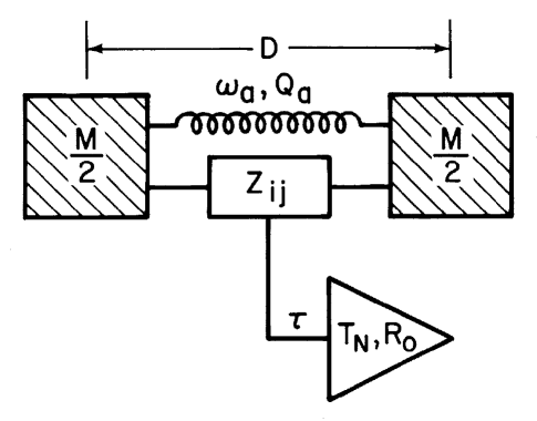
A GW detector is schematically shown in Figure 1. The antenna is parameterized in terms of its effective mass , length , (angular) resonance frequency , and quality factor . The transducer is characterized by its impedance matrix , which relates the input velocity and the output current with the input force and the output voltage by
| (4) |
The amplifier is characterized by its noise temperature , optimum source impedance , and integration time .
1. Detector Response to Signal and Noise
Let us consider a short pulse of GW which consists of one cycle of a sine wave with amplitude and (angular) frequency . The energy deposited by this pulse into a favorably oriented cylindrical antenna at rest can be shown to be
| (5) |
A careful treatment of all the noise terms of the detector [9] leads to the total noise energy
| (6) |
where is the forward energy coupling coefficient, is the reverse energy coupling coefficient, is the dimensionless impedance matching parameter, and is the integration time. Here is the signal bandwidth of the detector. We will confine our discussions to passive transducers, for which .
The two terms in Equation 6 represent the Brownian noise of the antenna-transducer system and the amplifier noise, respectively. Of the amplifier noise, the first term in the square brackets is due to the wide-band noise appearing at the output of the amplifier and the second term represents the so-called “back-action noise,” i.e., the amplifier noise fed back to the antenna. The Brownian motion noise can be reduced to an arbitrarily low level, in principle, by reducing . The amplifier noise, however, does have a fundamental limit. The noise temperature of linear amplifiers has a quantum limit, [10].
2. Optimization of Detector Parameters
Optimization conditions for detector parameters can be obtained as follows. Since the two terms in the square brackets of Equation 6 are proportional to and , respectively, must be chosen such that the two terms become equal, in order to minimize the total amplifier noise contribution (although the shortest is desirable to minimize the Brownian motion noise term). This leads to
| (7) |
The impedance matching parameter must satisfy in order to avoid blowing up any of the amplifier noise terms. With this choice, Equation 7 implies . This is a very important result. The fractional bandwidth of a resonant-mass antenna can approach unity if a near-unity can be achieved. A multi-mode transducer scheme can satisfy this condition, and will be discussed in the next section. The condition that the antenna-transducer system must satisfy in order for its Brownian motion noise to become negligible compared to the amplifier noise is given by
| (8) |
A wide-band detector thus reduces the requirement. If this condition is satisfied, the detector noise reaches the amplifier noise limit: . Finally, combining this with Equation 5, one obtains the minimum detectable signal:
| (9) |
The last expression here represents the standard quantum limit of the detection sensitivity. For the typical cylindrical antenna whose dimensions were given in Section II, the standard quantum limit corresponds to . So far second-generation resonant-mass detectors have reached about 100 times this level, due to their relatively high operating temperature, K, and limited amplifier noise, .
3. Multi-mode Transducer
As the amplifier noise approaches the quantum limit, K, the requirement for the antenna-transducer system becomes very severe. At the temperature of the third- and fourth-generation antennas, K, is required, even with , in order to reach the sensitivity given by Equation 9. Therefore, a wide-band transducer is of crucial importance.
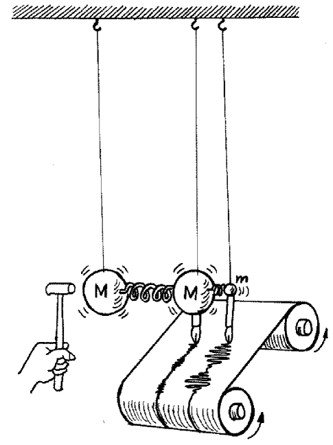
A resonant transducer has been introduced as the first step toward wide-band detection [11]. Its principle is illustrated in Figure 2. A small resonant mass is attached to the antenna with effective mass for cylinders). Then the frequency splits into and , and the energy flows back and forth between the antenna and the transducer with a beat frequency:
| (10) |
The amplitude gain of the transducer, , leads to improvement of roughly by a ratio of . There is an optimum transducer mass, , since too small a transducer mass results in an unacceptably long beat period which compromises . Since , one finds
| (11) |
The fractional bandwidth of the detector can be widened further by adding intermediate resonant masses between the antenna and the final transducer mass [12]. For an -mode system with a constant mass ratio between the neighboring masses, Equation 11 is generalized into
| (12) |
In principle, the fractional bandwidth can be increased arbitrarily close to unity by increasing . In practice, increasing complicates the construction and operation of the detector, and the bandwidth gain is slow beyond . Thus a three- or four-mode system will be a practical limit in most cases. A three-mode () detector with gives .
IV. Spherical Antennas of Gravitational Waves
The sensitivity reached with 4 K cylindrical detectors appears to be good enough to detect supernova events and coalescing neutron star binaries in our galaxy. However, the expected rates for these events are only one every 50 years or less [13]. In order to improve the event rates to about one a year, one needs to look all the way to the Virgo cluster of galaxies. This requires improvement of the detection sensitivity by another three orders of magnitude in amplitude, to , which is a factor of 10 beyond the standard quantum limit for the cylinders! Although back-action evasion is possible in principle to beat the standard quantum limit [14], the engineering challenge of reducing the thermal noise further in the antenna-transducer system makes it very difficult to realize in practice. Achieving a larger antenna cross section by using a larger effective mass or a material with a higher speed of sound may be a better approach. As will be shown, a spherical antenna should be able to provide the last factor of 10 improvement in sensitivity.
1. Advantages of a Spherical Antenna
A spherical antenna was originally proposed by Forward [15] as a means of detecting both the scalar and tensor gravitational waves predicted by various modern theories of gravity. The scalar wave would excite only the monopole () mode of the sphere whereas the tensor wave would interact with only the quadrupole () modes. Since there are five degenerate quadrupole modes to observe , , , , while there are only four unknowns for a GW signal, the two source angles and the amplitudes for the two polarizations , all these parameters could be determined with a single spherical antenna and the remaining fifth degree of freedom could be used to veto non-GW events.
Wagoner and Paik [7] computed the absorption cross section of a sphere and solved the inverse problem of determining the direction and polarization of the wave from the mode excitations. In particular, they found that, for the same total mass, a sphere has approximately five times the cross section of a cylinder averaged over the direction and the polarization. On the other hand, for the same antenna frequency and the same material, a sphere has roughly 20 times more mass than a typical cylinder. Thus the reduced cross section of a sphere is about 100 times greater than that of a cylinder:
| (13) |
This improves the amplitude sensitivity by a factor of 10, as required. Further, unlike the cylinder, the reduced cross section of a sphere is independent of the source direction. Thus a single antenna provides full-sky coverage with equal sensitivity and determines the source direction and the polarization [16]. A coincidence experiment across two identical spheres will give coincidence not only in time, but also in the direction and the polarization, and in the amplitude of excitation, a very strong criterion for coincidence! The sphere is indeed an ideal GW detector.
Another interesting property of a sphere is that higher harmonics of a larger sphere have significantly bigger cross sections than the fundamental modes of smaller spheres resonant at the same frequencies [17]. Therefore, the spheres could be instrumented as multi-frequency antennas.
2. TIGA Arrangement for Transducers
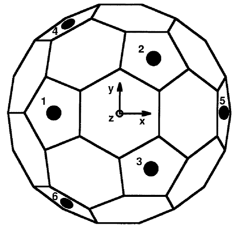
But how could one instrument the sphere with resonant transducers without destroying the degeneracy of the modes and disturbing the omni-directionality of the sphere? This important question was answered in recent papers by Johnson and Merkowitz [18, 19]. They proposed the so-called “TIGA” (Truncated Icosahedral Gravitational-wave Antenna) arrangement in which six radial transducers are mounted on six pentagonal surfaces in a hemisphere of a truncated icosahedron. These locations are shown by black dots in Figure 3. (The pentagonal surfaces alone form a dodecahedron.) The proposed six locations give the maximum isotropy and the resulting dodecahedron has the same symmetry as the sphere up to the quadrupole moment.
If the transducers are tuned to the frequency of the fundamental quadrupole modes of the sphere, the five antenna and the six transducer modes interact with each other to produce five degenerate modes at an upper frequency , five degenerate modes at a lower frequency , and one mode at the unshifted frequency . The beat frequency between the and modes is given by Equation 10 with for a sphere. The last mode corresponds to the monopole combination of the transducer outputs which does not interact with the sphere quadupole modes. Therefore, there must be five independent linear combinations of the transducer outputs of which each interacts uniquely with each of the five sphere modes.
Merkowitz and Johnson derived these linear combinations, called “mode channels” [19]. To do this, they first defined a new set of orthogonal sphere modes, described by real functions , such that
| (14) |
Let be the displacement response of the -th transducer. The mode channels are then defined as
| (15) |
Each transducer mode channel couples only to the corresponding sphere mode, and the antenna-transducer system behaves just like five independent two-mode cylindrical antennas. The optimal filtering algorithm developed for cylindrical antennas can be therefore be applied to each mode channel. The direction and polarization of the wave can be solved from the determined amplitudes of the sphere modes by using the method prescribed by Wagoner and Paik [7].
Another question that must be addressed is how one should suspend the sphere to maintain its symmetry along with its other nice properties. A nodal support from near its center of mass is certainly an attractive solution, which also provides additional vibration isolation. A multi-point support from the surface of the sphere should also work if the support structure has its lowest eigenfrequencies low compared to the antenna frequencies and the support cables are carefully tuned to reflect the sound waves at the antenna frequencies coming down from the room-temperature end.
V. Development Program for Spherical Detectors
With the advantages of spherical detectors clearly understood and with the questions on the transducer arrangement satisfactorily answered, the resonant-mass detector groups throughout the world are joining their efforts to build large ultra-cryogenic spherical detectors. A U.S. consortium consisting of research groups at Louisiana State University, University of Maryland, University of Rochester, and Santa Clara University has submitted to the National Science Foundation a joint R&D proposal for TIGA. If successful, this will lead to construction of large spherical antennas in the following few years. A Dutch consortium led by researchers at the University of Leiden has started R&D for a spherical antenna called GRAIL (Gravitational Radiation Antenna In Leiden). Groups in Italy and Brazil are also conducting research on spherical detectors. All these groups have joined together to form an international collaboration under the project name of OMEGA (OMni-directional Experiment with Gravitational-wave Antennas).
The present concept of the TIGA project is to build a “xylophone” of four aluminum alloy spheres with diameters ranging from 2 to 3 meters. The largest sphere will then weigh about 40 tons and have the lowest quadrupole frequency of about 900 Hz. A three-mode antenna-transducer system will allow a fractional bandwidth of 0.1. If both the fundamental and second harmonic quadrupole modes are instrumented, a frequency range of 800 to 2700 Hz will be be covered. The antennas will be cooled to 50 mK by He3/He4 dilution refrigerators. The baseline transducer for TIGA is a superconducting inductive transducer [11] coupled to a near-quantum-limited dc SQUID (Superconducting QUantum Interference Device). As a backup, an optical transducer based on a Fabry-Perot interferometer is also under development [20].
A denser, higher sound speed material is desirable for the antenna in order to increase its cross section. However, aluminum 5056 has been chosen tentatively because of its manufacturability into large spheres and its proven high mechanical quality factor. Explosive bonding techniques will permit construction of a 40 ton aluminum sphere. Samples of explosively bonded aluminum 5056 has been tested with good success. After annealing, a Q in excess of was measured in a torsional oscillator made out of the explosively bonded material [21]. This is very close to the highest Q ever measured in the monolithic material of aluminum 5056, and is within a factor of 2 from the value required for the standard quantum limit.
The superconducting transducer is electrically simple due to its passive nature and has operated reliably on a number of cryogenic antennas. It consists of just superconducting coils carrying a persistent current and a dc SQUID. Displacement of a superconducting test mass with respect to the coils modulates the persistent current and produces a time-varying magnetic flux which is detected by the SQUID. Significant progress has been made recently in the fabrication of a practical dc SQUID with low noise. A well-coupled dc SQUID with flux noise of about at a temperature below 100 mK has been demonstrated by Wellstood’s group at the University of Maryland [22]. A new SQUID with expected noise below has been fabricated and is undergoing tests. The test results of the optical transducer are also encouraging and an advanced system under design is expected to achieve similar sensitivity. The goal of the TIGA project is to operate the detectors at an overall noise of . The sensitivity of the largest sphere will then be .
The GRAIL project is more ambitious. They plan to cool a 100 ton copper-aluminum sphere to 10 mK [23]. The sphere will be 3 m in diameter and have the fundamental frequency at 700 Hz. A four-mode antenna-transducer system is envisioned with a thin-film superconducting inductive transducer [24] as the last stage.
Figure 4 shows the expected sensitivity of the TIGA xylophone of four spheres. The first four curves (solid lines) represent the sensitivities of the lowest quadrupole modes and the second four curves (dashed lines) are those of the second harmonic quadrupole modes. The two dotted curves represent the expected sensitivities of the first and advanced LIGO, respectively. One can see that, although their bandwidths will be somewhat restricted, the spherical detectors will have sensitivities in their own bandwidths comparable to the long-baseline laser interferometers. Therefore, the spherical antennas will complement the interferometers, at a modest increase in cost, with better resolution of the source direction and polarization as well as full-sky coverage.

VI. Gravitational-Wave Astronomy with Spheres
What astrophysical sources will be observed by the fourth-generation resonant-mass detectors? It is difficult to tell because unexpected events may be detected as has always happened whenever new windows were opened for optical, x-ray, infrared, and gamma-ray astronomy. According to the present theories, however, only a few GW sources have been analyzed to the extent that numerical waveforms have been computed. Although these are not completely relativistic calculations yet, they provide a useful guide for the design of the next-generation detectors.
Coalescing neutron star binaries are one type of source for which waveforms have been computed [25]. Harry et al. used these waveforms to calculate the expected signal-to-noise ratio for the TIGA array [26]. For two 1.4 neutron stars at the distance of 15 Mpc (the approximate distance to the Virgo cluster), they found total energy signal-to-noise ratios (summed over the four spheres) of 25.8 and 0.51 for the inspiral and the coalescence phase, respectively. This is to be compared with the expected energy signal-to-noise ratios of the first LIGO of 38.0 and 0.010, respectively. For the inspiral phase, LIGO has greater sensitivity because of its wider bandwidth that extends down to 300 Hz. For the coalescence phase, however, the TIGA xylophone has greater sensitivity because the signal is confined to frequencies above 1300 Hz. Therefore, the spheres will have a better chance to peer through to the relativistic dynamics during the actual coalescence. The expected event rate for the above signals is less than 0.1 per year.
Another source for which waveforms have been computed is the bar mode instability of a rapidly rotating star formed during a supernova [27]Although the equatorial radius of such a star is quite uncertain, for km, most of the signal power is concentrated between 1 and 2 kHz where the spheres have the best sensitivity. Thus, for a rotating star of mass 1.4 and equatorial radius 20 km at the distance of 1 Mpc, the TIGA array has the total energy signal-to-noise ratio of 51.8 in contrast to 0.88 for the first LIGO. The expected event rate for supernovae out to that distance is about 0.1 per year.
Clearly, we need help from our theoretical colleagues to compute more precise waveforms and signal amplitudes for all plausible GW sources. For a wide-band detector like a laser interferometer, the exact waveform is even more important since, without it, a template cannot be constructed to search for an event of a particular type.
Laser interferometers under construction and the spherical detectors on the drawing boards are expected to be sensitive enough to detect extragalactic GW events. The next decade may be one of the most exciting times in gravitation and astrophysics as a new window opens for astronomy. After so much hard work pushing the frontiers of materials, cryogenics, and sensor technology for decades, with the sole purpose of improving detectors for nature’s most elusive wave, it is about time to do some real science with these new devices!
Acknowledgements
I would like to acknowledge useful discussions with Thomas Stevenson, Gregg Harry, Fred Wellstood, Insik Jin, and Charlie Misner. This work was supported in part by the National Science Foundation under grant PHY93-12229.
REFERENCES
- [1] A. Einstein, Sitz. Preuss. Akad. Wiss. (1916), p.688; (1918), p.154
- [2] E. Coccia, G. Pizzella, and F. Ronga (editors), Gravitational Wave Experiments (World Scientific, Singapore, 1995).
- [3] A. Astone et al., Europhys. Lett. 16, 231 (1991).
- [4] M. Cerdonio et al., Nucl. Phys. (Proc. Suppl.) 35, 75 (1994).
- [5] A. Abramovici et al., Science 256, 325 (1992).
- [6] C. Bradaschia et al., Nucl. Instrum. Methods A 289, 518 (1990).
- [7] R.V. Wagoner and H.J. Paik, in Proceedings of International Symposium on Experimental Gravitation (Accademia Nazionale dei Lindei, Rome, 1977), p. 258.
- [8] C.W. Misner, K.S. Thorne, and J.A. Wheeler, Gravitation (W.H. Freeman, San Francisco, 1973), Chapter 37.
- [9] R.P. Giffard, Phys. Rev. D 14, 2478 (1976).
- [10] H. Heffner, Proc. IRE 50, 1604 (1962).
- [11] H.J. Paik, J. Appl. Phys. 47, 1168 (1976).
- [12] J.-P. Richard, Phys. Rev. Lett. 52, 165 (1984).
- [13] K.S. Thorne, in Proceedings of the Snowmass 95 Summer Study on Particle and Nuclear Astrophysics and Cosmology, edited by E.W. Kolb and R. Peccei (World Scientific, Singapore) (to be published).
- [14] C.M. Caves et al., Rev. Mod. Phys. 52, 341 (1980).
- [15] R.L. Forward, Gen. Rel. Grav. 2, 149 (1971).
- [16] C.Z. Zhou and P.F. Michelson, Phys. Rev. D 51, 2517 (1995).
- [17] E. Coccia, J.A. Lobo, and J.A. Ortega, Phys. Rev. D 52, 3735 (1995).
- [18] W.W. Johnson and S.M. Merkowitz, Phys. Rev. Lett. 70, 2367 (1993).
- [19] S.M. Merkowitz and W.W. Johnson, Phys. Rev. D 51, 2546 (1995).
- [20] J.-P. Richard, Phys. Rev. D 46, 2309 (1992).
- [21] W. Duffy, Jr. and S. Dalal, Cryogenics (to be published).
- [22] F.W. Wellstood et al., in Proceedings of the First International Workshop for an Omni-directional Gravitational Radiation Observatory, São José dos Campos, Brazil, May, 1996 (to be published).
- [23] G. Frossati, in Proceedings of the First International Workshop for an Omni-directional Gravitational Radiation Observatory, São José dos Campos, Brazil, May, 1996 (to be published).
- [24] T.R. Stenvenson, Ph.D. thesis, Stanford University, Stanford, California (1991).
- [25] X. Zhuge, J.M. Centrella, and S.L.W. McMillan, Phys. Rev. D 50, 6247 (1994).
- [26] G.M. Harry, T.R. Stevenson, and H.J. Paik, Phys. Rev. D (in print).
- [27] S.C. Smith, J.L. Houser, and J.M. Centrella, Astrophys. J. (to be published).