address=Dipartimento di Fisica, Università di Trento, and I.N.F.N., Gruppo di Trento, Povo (TN), Italy address=Dipartimento di Fisica, Università di Trento, and I.N.F.N., Gruppo di Trento, Povo (TN), Italy address=Dipartimento di Fisica, Università di Trento, and I.N.F.N., Gruppo di Trento, Povo (TN), Italy address=Dipartimento di Fisica, Università di Trento, and I.N.F.N., Gruppo di Trento, Povo (TN), Italy address=Dipartimento di Fisica, Università di Trento, and I.N.F.N., Gruppo di Trento, Povo (TN), Italy address=Dipartimento di Fisica, Università di Trento, and I.N.F.N., Gruppo di Trento, Povo (TN), Italy
Torsion pendulum facility for direct force measurements of LISA GRS related disturbances
Abstract
A four mass torsion pendulum facility for testing of the LISA GRS is under development in Trento. With a LISA-like test mass suspended off-axis with respect to the pendulum fiber, the facility allows for a direct measurement of surface force disturbances arising in the GRS. We present here results with a prototype pendulum integrated with very large-gap sensors, which allows an estimate of the intrinsic pendulum noise floor in the absence of sensor related force noise. The apparatus has shown a torque noise near to its mechanical thermal noise limit, and would allow to place upper limits on GRS related disturbances with a best sensitivity of 300 fN/ at 1mHz, a factor 50 from the LISA goal. Also, we discuss the characterization of the gravity gradient noise, one environmental noise source that could limit the apparatus performances, and report on the status of development of the facility.
Keywords:
LISA, LTP,GRS, Torsion Pendulum:
04.80Nn, 07.10Pz, 07.87+v, 95.55YnSubmitted to Proc. of the Int. LISA Symposium, AIP Conference Proceedings, 2006
1 Introduction
The LISA gravity wave sensitivity goal requires that the residual acceleration of its test masses (TMs) must be kept below 3 fm/s2/ down to 0.1mHz bender:LISA . This is obtained with a Drag-Free Control, with the spacecraft that shields the TMs from environmental disturbances and is centered about the TMs geodesic motion according to a position sensor, also called “Gravity Reference Sensor” (GRS). The current design of the LISA GRS foresees cubic 2 kg and (46 mm)3 TMs, surrounded by an array of electrodes included in a capacitive readout and actuation scheme weber:sensor ; dolesi:sensor . In preparation for the flight-test of the LISA core elements, LTP vitale:LTP , relevant upper limits on the most important GRS related surface disturbances have been already set by means of torsion pendulums carbone:prl ; carbone:char . These experiments used a single LISA-like TM, hanging in axis from a torsion fiber and surrounded by one GRS prototype: this configuration is extremely sensitive to torques arising in the GRS but is insensitive to net forces and to any source acting along axes passing through the center of the TM. Upper limits on force noise sources have been thus set using model-dependent arm-lengths, to convert the torques into forces hueller:upperlimits .
To overcome this limit, we are developing a new torsion pendulum facility, employing a four TM configuration hoyle:4mass , that allows for a direct measurement of force disturbances arising in the GRS. We present here results with a first prototype pendulum that allows an estimate of the intrinsic pendulum performance. We discuss the characterization of the gravity gradient noise, one environmental noise source that could limit the apparatus performances, and finally report on the status of development of the facility.
2 Development of the facility
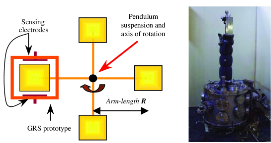
A sketch of the experiment concept is shown in fig.1, with a photograph of the facility. Four LISA-like TMs lay on the horizontal plane, are mounted on a cross-shaped support, and are suspended off-axis with respect to the pendulum torsion fiber, at distance bigger than the TM side-length. One of the TMs is included in a GRS prototype: any net force arising inside the GRS gets thus converted into a torque on the pendulum by the arm-length . This pendulum has full sensitivity to disturbances arising inside the sensor, independently from their location, and the unique conversion arm-length allows to set model-independent force noise upper-limits. Use of hollow TMs reduces the pendulum weight and allows for thinner torsion fibers. This makes the pendulum mainly sensitive to surface forces (however the most relevant envisioned by noise analyses) but increases its force sensitivity, that can be further enhanced by enlarging the pendulum arms, in an optimal compromise with low weight and coupling to gravity gradients (see below). The direct measurement of GRS relevant parameters like force gradients (“stiffness”) or stray electrostatic forces will provide then fully representative estimates for LISA.
The main component of the facility is a 250 vacuum vessel (see fig.1), accomodating the pendulum and the GRS, that sits on a concrete slab partially isolated from the laboratory floor. A 90 cm long tube encloses the torsion fiber. A 400 turbo pump sets the residual pressure at mBar. The entire apparatus is enclosed in a thermally insulated box whose temperature is controlled by a thermalized water bath stabilizing the air circulating inside a heat exchanger. The experiment is equipped with manual micro-manipulators (4 dof for GRS alignment + 2 dof for pendulum rotational/vertical alignment) and motorized stages (2 translators for GRS alignment and automatized stiffness measurements). The pendulum motion is monitored by a commercial autocollimator, with 50 nrad resolution for both twist and tilt modes. The pendulum tilt motion is suppressed with a magnetic eddy current damper (decay time s). Finally, the facility is equipped with different environmental monitors, like thermometers for in-vacuum and in-air temperatures, two 3-axis flux-gate magnetometers for magnetic fields and field gradients and a 2-axis tilt-meter for the residual tilt motion of the apparatus.
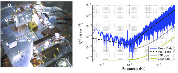
As the main GRS-related noise sources are expected to depend strongly on the TM-electrode separation (gap), an estimate of the intrinsic pendulum noise floor has been performed with a prototype pendulum integrated with very large-gap sensors (allowing us also to debug the facility and verify the fiber performances). We employed (3 cm)3 solid uncoated Al TMs ( g), mounted on an Al cross shaped support and centered at a distance of 89 mm from the fiber axis (see fig.1). A Au-coated mirror was mounted along the fiber axis. The total pendulum weight was g, roughly the same of the next pendulum, with (46 mm)3 TMs. Two single axis capacitive sensors surrounded two of the TMs (electrically isolated) at very large gaps (8 mm along the force sensitive axis), providing both a high sensitivity (200 nrad /) readout of the pendulum twist motion and actuation authority. We used a 95 cm long, 50 m diameter W fiber, with a measured mechanical quality factor . With the pendulum inertia g m2 and a torsion constant nNm/rad, the torsion pendulum resonance was mHz.
A typical force sensitivity performance of the apparatus, obtained by dividing the measured pendulum torque noise by the arm-length mm, is shown in fig.2. Below 1 mHz, the observed noise is within a factor 2 from the instrumental limit, set here by the pendulum mechanical thermal noise. Above 1 mHz, the sensitivity is limited by the angular read-out noise. The performance shown in fig.2 would allow to place upper limit on the disturbances related to a GRS prototype at the level of 800 fN/ between 0.2 and few mHz, with a best sensitivity of 300 fN/ at 1 mHz, a factor 50 from the LISA goal. The excess noise at low frequencies, that could be given by environmental temperature fluctuations as well as tilt motion of the apparatus, is still being investigated.
A possible drawback of this four mass pendulum configuration is its sensitivity to gravity gradients hoyle:4mass ; Y:Su . The gravity gradient torque induced on a pendulum by objects at a distance goes like , with and , respectively, the characteristic radius and degree of symmetry of the pendulum mass distribution about the torsion axis. This pendulum symmetry is nominally high, with . However, lower order terms, particularly quadrupole, could enter through machining and assembling imperfections, producing mass distribution asymmetries and tilting of the pendulum: this enhances the pendulum sensitivity to gravity gradients and avoids reaching its ultimate performances.
In order to qualitatively characterize the role of gravity gradient noise of our experimental site, we performed a test in which we purposely enhanced the pendulum quadrupole moment () to detect any induced excess noise on the pendulum. Two of the four masses where moved towards the center of the pendulum by mm, as shown in fig.3. If the previous configuration had a “nominally” nulled quadrupole moment, i.e. , this produced a (calculated) mass quadrupole moment of the pendulum of order g m2 (for comparison, a 1 cm displacement would produce g m2, and a 2 mm displacement g m2).
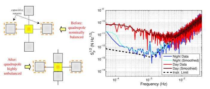
Measured force noise spectra are shown in fig.3. When human activity is present close to the experiment, in particular due to people working at few m from the apparatus, the observed force noise is about a factor 50 higher than the instrumental limit. However, when human activity inside and near the lab is reduced (night and week-ends) we did not observe any excess noise compared to the typical performance of the pendulum, as in fig.2. With reasonable tolerances of the final (46 mm)3 TM assembly of order 100 m (or better), the mass quadrupole moment of the pendulum will be reduced at least by a factor 300, compared to the one in fig.3. This would make gravity gradient noise to be substantially negligible for the pendulum performance. Even if this test provides only a partial picture of the gravity gradient noise of our experimental site (this is only one of the possible pendulum assembling imperfections, as for instance tilting with respect to the vertical axis, for which we did not perform a specific investigation), this test shows that quadrupole gravity gradient noise should not represent a relevant limitation for reaching the ultimate pendulum performance in terms of force sensitivity.
3 Future work: Tests with the LTP GRS
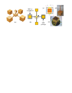
We are now working on the integration of a fully representative GRS prototype to be tested in the facility. A new pendulum, shown in fig.4, is currently under construction, employing four Al (mm)3 hollow TMs. One TM will be included into a GRS prototype that implements the LTP design. An additional capacitive sensor, implemented with very large gaps and needed to compensate the tilt-twist coupling induced on the pendulum by the GRS-related stiffness, will surround the opposite TM. This “stiffness compensator” will also be the support for an optical read-out proposed for LISA by our INFN collaborators DiFiore . These two TMs will be electrically isolated, for the capacitive readout and actuation. For electrostatic homogeneity, the remaining two TMs will be electrically grounded to the rest of the pendulum and then to the fiber. Similarly, the whole pendulum will be Au-coated, included TMs and cross shaped support.
This facility will allow to test GRS prototypes for LTP and LISA with full-size TMs and highly representative conditions of the flight mission. By direct measurement of forces instead of torques, it will allow stringent upper limits on LISA force noise, which will be independent of the model of the noise source and its location within the GRS. Furthermore, the role of the sources that produce force noise on the LISA TMs will be more straightforward to evaluate and model, leading to a more accurate verification of the LISA noise model.
The authors would like to thank E.Adelberger and C.D.Hoyle for many useful discussions on the gravity gradient issue. This work was supported by ASI, ESA and INFN.
References
- (1) Bender P et al., LISA ESA-SCI(2000)11, 2000
- (2) Weber W J et al.2002 SPIE Proc. 4856 31
- (3) Dolesi R et al.2003 Class. Quant. Grav.20 S99
- (4) Anza S et al.2005 Class. Quant. Grav.22 S125
- (5) Carbone L et al.2003 Phys. Rev. Lett.91 151101
- (6) Carbone L et al.2005 Class. Quant. Grav.22 S509
- (7) Carbone L et al.2004 Class. Quant. Grav.21 S611
- (8) Carbone L et al.Proc. of 10th Marcel Grossmann Meeting on General Relativity, gr-qc/0411049
- (9) Y. Su et al.1994 Phys. Rev. D 50, 3614
- (10) Di Fiore L. et al., this conference proceedings