Interferometers for Displacement-Noise-Free Gravitational-Wave Detection
Abstract
We propose a class of displacement- and laser-noise free gravitational-wave-interferometer configurations, which does not sense non-geodesic mirror motions and laser noises, but provides non-vanishing gravitational-wave signal. Our interferometer consists of 4 mirrors and 2 beamsplitters, which form 4 Mach-Zehnder interferometers. By contrast to previous works, no composite mirrors are required. Each mirror in our configuration is sensed redundantly, by at least two pairs of incident and reflected beams. Displacement- and laser-noise free detection is achieved when output signals from these 4 interferometers are combined appropriately. Our 3-dimensional interferometer configuration has a low-frequency response proportional to , which is better than the achievable by previous 2-dimensional configurations.
pacs:
04.80.Nn, 06.30.Ft, 95.55.YmIt was recently demonstrated theoretically that gravitational-wave (GW) detection does not require freely falling test masses, because non-geodesic test-mass motion affect travel times of pulses only when they arrive and leave the test masses, while the effect of GWs are distributed KC1 . This idea was further explored in Ref. KC2 , which shows that once the number of test masses is large enough, the number of light-pulse-travel-time measurement channels between test masses [] will exceed the total number of clock- and displacement-noise channels [], and there must exist clock- and displacement-noise-free channels. Ref. KC2 also showed that interferometers can be combined to realize displacement- and laser-noise free GW detection. As argued there, when lasers are used as part of the detection strategy, motions of the laser devices cause Doppler shift to the laser frequencies, and are indistinguishable from laser noises. Therefore, displacement-noise-free detection, strictly speaking, requires the cancelation of laser noise. Henceforth, we shall use the term Displacement-noise-free Interferometry (DFI) to describe displacement- and laser-noise free interferometer configurations.
Refs. KC1 and KC2 study DFI by calculating pulse time delays between emitters and receivers, which are fixed on point test masses. This approach, although mathematically simpler and in principle applicable to laser interferometry, does not provide practical interferometer configurations right away. In particular, interferometer configurations constructed so far require composite mirrors, namely mirrors with multiple reflective surfaces. Apart from being experimentally challenging, the use of composite mirrors gives rise to the fundamental difficulty that thermal fluctuations of relative positions between the multiple reflective surfaces are not canceled. In addition, so far only 2-dimensional configurations have been explored, for which it can be proved that sensitivity to GWs can be no better than in low frequencies KC4 .
In this paper, we propose a class of 2-D and 3-D interferometers that implement DFI without using composite mirrors. Although these configurations were initially discovered using linear algebraic manipulations within the time-delay formulation in Ref. KC2 , they turn out to have very simple physical interpretations. First of all, we use Mach-Zehnder interferometry, so that laser noises can be canceled right in the beginning. Moreover, each mirror participates in at least two Mach-Zehnder interferometers, and thus has its location sensed redundantly. Finally, by combining the Mach-Zehnder output signals, we are able to cancel amongst the redundant displacement information, leaving non-vanishing response to GWs. In particular, we will show that our 3-D configuration has sensitivity in low frequencies, which is the best one can achieve with DFI KC4 . The 2-D configuration, which has response in low frequencies, is proposed mainly for the purpose of initial experimental tests.
GW response of a plane electromagnetic (EM) wave. For self-containedness, we provide a brief derivation of the GW-induced phase shift of light. A weak plane GW on Minkowski background can be described with a metric
| (1) |
in the Cartesian coordinate system, , with the time coordinate, the spatial coordinates, and . In the Transverse-Traceless (TT) gauge, only has spatial components:
| (2) | |||||
Here is a spatial orthonormal set, with the wave propagation direction. We approximate the EM field as a scalar wave, with amplitude
| (3) |
with the 0-th order EM wave when there is no GW ( is constant), and the additional phase shift caused by the GW. The EM wave equation , expanded to leading order in and , can be written as
| (4) |
where the Lorenz gauge condition has been used. Because is slowly varying compared to , we can ignore terms like on the left-hand side, and obtain
| (5) |
which accumulates along the path of the light ray in Minkowski spacetime. In particular, if the Minkowski ray starts from and ends at , with and , then the GW-induced phase shift is
| (6) | |||||
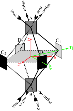
3-D Configuration. We now discuss our 3-D configuration, shown in Fig. 1. The mirrors are located on the 8 vertices of a regular octahedron, with edge length . All light rays in our interferometer will be propagating along the edges of the octahedron. A Cartesian coordinate system is attached to the octahedron, with the origin coinciding with its center, axis coinciding with its - axis, axis parallel to the - (-) direction, and axis parallel to the - (-) direction. [We have also defined and directions, as shown in the figure.] A - beamsplitter each is located on the vertices and , with normal directions parallel to the axis. The four perfectly reflective mirrors at and are such oriented that light rays from will be reflected directly to . We assume all perfect mirrors to have amplitude reflectivity , and both 50-50 beamsplitters to have amplitude reflectivity for light incident from the side (i.e., traveling toward direction), and amplitude reflectivity for light incident from the side; the edge length is assumed to be an integer multiple of the optical wavelength, at the zero point of the device (i.e., in absense of laser noise, non-geodesic mirror motion, and GW).
In this mirror set-up, we construct four Mach-Zehnder interferometers, , (with light paths in solid lines), and (with light paths in dashed lines), with input and output ports indicated in Fig. 1. At the zero point, the ports , , , and are all dark, while each input port is also the bright port for another interferometer. During operations, for each Mach-Zender, , if and represent the additional phase shifts gained by the beams transmitted and reflected from its first beamsplitter, respectively, then the output optical amplitude is proportional to
| (7) |
For interferometers and , the “first beamsplitter” means , while for and , it means . In Eq. (7), we always have the minus sign in front of , because the lasers always incident from the side of the beamsplitters, and hence the first reflection always encounters a amplitude reflectivity.
Physically, the additional phase shifts can arise from laser noise, displacement noise, and GWs. Because we only consider linear order in GWs and the noises, we can first include only effects of laser and displacement noises, construct a combination from the outputs of the four Mach-Zehnder interferometers that is free from these noises, and then calculate its response to GWs. For dark-port detection, each Mach-Zehnder interferometer is already free from laser noise; we only need to evaluate their displacement sensitivities. For a mirror with normal direction and incident wavevector , the phase shift gained by the reflected light when the mirror moves spatially by is . For and interferometers, we have
| (8) | |||||
| (9) | |||||
| (10) | |||||
| (11) |
Here, denotes the motion of along the axis and so on. Thus we have
| (12) | |||||
Here, we have denoted with the optical frequency and the speed of light. Note that motions of and are already canceled in this subtraction, because the two Mach-Zehnders sense their motions equally, due to the fact that . Similarly, we have a combination of the other two Mach-Zehnders:
| (13) | |||||
As a consequence, the total combination
| (14) |
is free from any displacement noise. This is also anticipated, because it is obvious that and sense the beamsplitters in the same way, and so do and .
We now calculate the response of to GWs. For a particular case, with a plane GW coming directly along the axis [i.e., , Cf. Eq. (2)] and
| (15) |
it is easy to argue based on octahedron’s symmetry, and the way we combine the signals, that beams in all four branches, i.e., those involving , , and respectively, will give equal GW contributions to the final combination. For one particular branch, involving , we calculate the GW response, using Eq. (6):
| (16) | |||||
In the frequency domain, we have
| (17) | |||||
where and are Fourier transforms of and . This already shows a non-vanishing response.
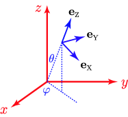
For GWs with generic propagation directions and polarizations, we use the following notation (Cf. Eq. (2) and Fig. 2),
| (18) | |||||
| (19) | |||||
| (20) |
In low frequencies, the GW response of the DFI combination is , with 111This angular response, although looks similar to that of a Michelson interferometer lying on the - plane, in fact cannot be put into that form, regardless of the orientation of the Michelson. In particular, the response of a Michelson with arms along and is ; that of a Michelson rotated by from this one is .
| (21) | |||||
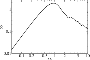
For general frequencies and generic incoming GW, the analytical formula for the transfer function is very complicated. Instead, as in Ref. KC2 , we show the root-mean-square response function, averaged over GW propagation direction and polarization angle, in Fig. 3.
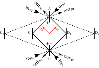
2-D Configuration. For experimental tests, it is desirable to have a 2-D configuration. It is straightforward to “squash” our 3-D configuration in Fig. 1 into a 2-D configuration, as shown in Fig. 4. It also consists of 4 Mach-Zehnder interferometers, , (inner Mach-Zehnders, shown in solid lines in the figure), , and (outer Mach-Zehnders, shown in dashed lines in the figure). Similar to the 3-D configuration, the subtraction of from cancels displacements of and ; subtraction of from cancels displacements of and . The combination of all four interferometers can cancel motions of the beamsplitters in addition.
It is easy to demonstrate the possibility of canceling beamsplitter displacements without eliminating sensitivity to GWs, by looking at a special case, in which form a square, and
| (22) | |||||
| (23) |
We also assume that GW with wavelength propagates perpendicular to the detector plane, with polarization of (see Fig. 4). For the the inner Mach-Zehnders, each of which consists of 4 beams, it is easy to demonstrate that, among them, we have
| (24) | |||||
Here we need to use the fact that GW phase shift flips sign: (i) between beams along and those along , and (ii) after a time delay of . For example, with respect to , gains a minus sign twice: the first due to GW polarization, because is along , while is along ; the second because the beam starts accumulating GW phase shift exactly half an oscillation period after . Following Eq. (24), GW phase gained by all beams in the inner Mach-Zehnders add up, and there is non-vanishing GW response. On the other hand, the outer Mach-Zehnders do not sense the GW, because GW phase shift, after accumulation by exactly one oscillation period, is zero in each link. This means we can subtract just the correct amount of output from the outer Mach-Zehnders to cancel sensitivity to beamsplitter motions, while keeping the non-vanishing GW response of the inner Mach-Zehnders. However, as further calculations indicate, the low-frequency response of this 2-D configuration is KC4 .
Concluding Remarks. This paper brings Displacement-noise-free Interferometry (DFI) from conceptual plausibility KC1 ; KC2 to concrete and practical optical designs. We provided simple interferometer configurations that realize DFI. Compared with the conceptual design in Ref. KC2 , our 4-Mach-Zehnder configurations are far more straightforward to implement: instead of requiring composite mirrors with fixed relative positions, our 4-Mach-Zehnder interferometers only require that centers of the multiple beams that reflect off the same mirror must coincide with each other. Moreover, our 3-D configuration has superior low-frequency response (, which cannot be exceeded by any DFI configurations) compared to 2-D configurations (which cannot exceed ).
At the end of this paper, we raise the possibility that our 4-Mach-Zehnder configuration be applied to atomic interferometers proposed for GW detection Chiao , mainly for two reasons: (i) the proposed atomic interferometers already have Mach-Zehnder configurations, and (ii) with much shorter arms compared to long-baseline laser interferometers, displacement noise is likely to become a challenging issue for these detectors.
Acknowledgment. We thank Curt Cutler for brining Octahedron into our attention. Research of Y.C., A.P. and K.S. are supported by Alexander von Humboldt Foundation’s Sofja Kovalevskaja Programme (Funded by the German Ministry of Education and Research). R.L.W. was supported by the U.S. National Science Foundation under Cooperative Agreement PHY-0107417.
References
- (1) S. Kawamura and Y. Chen, Phys. Rev. Lett. 93, 211103 (2004).
- (2) Y. Chen and S. Kawamura, gr-qc/0504108, submitted to Phys. Rev. Lett. (2005).
- (3) Y. Chen et al., in preparation.
- (4) R.Y. Chiao and A.D. Speliotopoulos, J. Mod. Opt., 51, 861 (2004).