Compensation of Strong Thermal Lensing in High Optical Power Cavities
Abstract
In an experiment to simulate the conditions in high optical power advanced gravitational wave detectors such as Advanced LIGO, we show that strong thermal lenses form in accordance with predictions and that they can be compensated using an intra-cavity compensation plate heated on its cylindrical surface. We show that high finesse 1400 can be achieved in cavities with internal compensation plates, and that the cavity mode structure can be maintained by thermal compensation. It is also shown that the measurements allow a direct measurement of substrate optical absorption in the test mass and the compensation plate.
pacs:
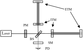
04.80.Nn, 95.55.YmLaser interferometric gravitational wave (GW) detectors employ advanced Michelson interferometers to detect the differential strain produced in the two arms by a passing GW. A schematic of an advanced GW detector is shown in Fig. 1b1 . Fabry-Perot cavities are placed in the arms of the interferometer to increase the stored power, thereby increasing the sensitivity of the detector. The mirrors for these cavities (the inboard test mass (ITM) mirror and end test mass (ETM) mirror) will be separated by 4 km in Advanced LIGOb1 and will have radii of curvature of about 2 km, producing TEM00 beam radii of about 6 cm at the mirrors. Operating the interferometer on a dark fringe and using the signal-recycling mirror (SM) to enhance resonantly the signal sidebands further increases the sensitivity. The power travelling back towards the laser is resonantly reflected back into the interferometer by the power-recycling mirror (PM), thereby reducing the required laser power.
In advanced interferometers, the stored power will be increased significantly to improve the detector sensitivity. In Advanced LIGO, for example, it is expected that about 1 kW will be incident on the back surface of the ITMs and about 830 kW may be stored in the arm cavities. This will increase the sensitive range for neutron star inspiral events from the present 10 Mpc to about 200 Mpc, thus leading to a signal event rate of many per year b2 . However, heating due to absorption in the beam splitter (BS) and ITM substrates, and in the reflective coatings of the ITM and ETM is expected to cause significant wavefront distortion of the optical modes of the interferometer b3 ; b4 ; b5 ; b6 ; b7 ; b8 ; b9 . This distortion, also referred to as thermal lensing, would reduce the sensitivity of the detector and could lead to instrument failure b4 . Indeed, compensation of thermal lensing due to excess absorption in an ITM has already found to be required in the initial LIGO interferometer b10 ; b11 . In that case, a CO2 laser beam is used to heat the back surface of the ITM to cancel the positive lens produced by absorption b12
The High Optical Power Test Facility (HOPTF), located at Gingin in Western Australia, has been developed to investigate the effects of optical absorption and its compensation in optical cavities with high stored power b13 . It has a maximum cavity length of 80 m and currently has a single-frequency 10 W Nd:YAG laser b14 . Though not in use in the experiments reported here, auto-alignment of the laser beam into the optical cavity b15 has been achieved. An off-axis Hartmann wavefront sensor that will allow spatially resolved, sensitive measurements of the wavefront distortion in the ITM and CP b16 will shortly be installed.
In this letter we report on the observation and characterization of strong thermal lensing in the sapphire ITM, caused by a distortion that is similar in magnitude to that expected in Advanced LIGO, and its compensation using direct heating the cylindrical surface of a fused silica compensation plate inside the cavity. The distortion does not cause our optical cavity to become unstable as the change in effective curvature of the ITM is small compared to the curvature of the ETM. In an advanced interferometer, however, this curvature would be similar to that of the cavity mirrors.
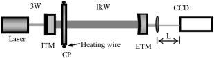
Initially, we are investigating the effects of absorption in the substrate of a sapphire ITM using a simple Fabry-Perot cavity that has a rear-surface input-coupler. The layout of the experiment is shown in Fig. 2 and the parameters of the cavity are listed in Table 1. An intra-cavity Compensation Plate (CP) is also included in the cavity. The CP is conductively heated on its cylindrical surface and is located near the ITM. While the CP in our experiment is directly mounted on a breadboard, the CP in an advanced detector would be suspended and radiatively heated to avoid noise coupling. The measured cavity lifetime was about 118 ms, giving a finesse of about 1400. The cold-cavity beam waist was 8.7 mm.
| ITM | ETM | CP | |
| Radius of Curvature (m) | Flat | 720 | Flat |
| Materials | Sapphire | Sapphire | Fused Silica |
| Diameter (mm) | 100 | 150 | 160 |
| Thickness (mm) | 46 | 80 | 17 |
| HR transmission (ppm) | 1840 100 | 20 | |
| AR reflectivity (ppm) | 29 20 | 12 12 | 100 |
| Cavity internal power (kW) | 1.0 | ||
| Cavity length (m) | 77 |
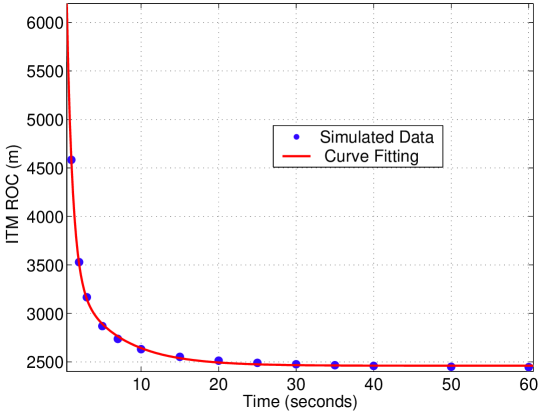
The expected wavefront distortion was calculated using a Finite Element Model (FEM) and assuming an absorbed power of 0.5 W, corresponding to a substrate absorption coefficient of 50 ppm/cm and 1 kW circulating power. The radius of curvature due to heating of the ITM substrate is about 2.5 km, comparable to that expected for an advanced GW interferometer using fused silica as the test mass material b17 . The predicted time dependence of the change in effective curvature of the ITM due to substrate absorption is shown in Fig. 3.
The time dependence can be described by the sum of two exponentials with time constants and . The first is due to the time constant for heating the Gaussian beam profile within the test mass. The second characterizes the much longer time it takes the test mass to come into equilibrium with the heated beam volume. This is consistent with the analytical model of Hello and Vinet b17 , which predicts an infinite set of exponentials with rapidly decreasing time constants, of which only the longest will be discernible. For our sapphire ITM, we find that = 0.76 s and = 5.91 s. It is interesting to note that the value of the time constants 1 and 2 slightly depend on the mirror geometry and so are only valid for the HOPTF ITM. Fig. 3 also shows a comparison of the predictions of the FEM model and the exponential fit. The thermal lensing of the fused silica compensation plate (CP) can be similarly modelled, yielding time constants of = 7.40 s and = 50.1 s.
The effect of the thermal lensing and compensation was measured using the beam transmitted through the ETM, as described in Fig. 2. The time dependence of the beam radius at the ETM, calculated using the beam radius at the CCD, and the transmitted power are plotted in Fig. 4. The recorded spots were accurately described by a fundamental transverse mode Gaussian intensity profile and no obvious asymmetric distortion was observed. The cold-cavity beam radius at the CCD was 1.0 mm, corresponding to the beam radius of 9.3 mm at the ETM. As expected, thermal lensing at the ITM decreases the beam size at the ETM.
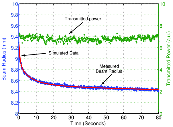
Since the time constants for the thermal lensing are known, only 2 free parameters, the powers absorbed by the ITM and CP, can be used to fit the expected time dependence to the measurements. The solid line in Fig. 4 shows this time dependence for absorbed powers of 0.51 W and 5.5 mW, respectively. The absorbed power in the ITM corresponds to absorption of 51 ppm/cm in the ITM.
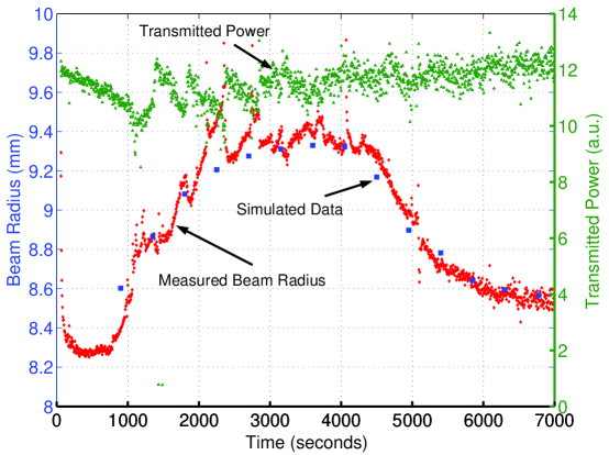
Compensation of the thermal lens is shown in Fig. 5. The rapid evolution of the thermal lens is just discernable at time zero, as the ETM beam radius reduces from 9.4 mm to 8.3 mm. Heating (9.5 W) was applied to the CP at time t = 450 s and stopped at t = 4026 s. The glitches in the measurements are due to fluctuations in the stored power, also shown in Fig. 5, caused by changes in the alignment of the cavity and input beam.
The compensation was simulated using a model similar to that used for the simulation of the thermal lensing with additional conduction heating of the CP. The results, shown as squares in Fig. 5, agree reasonably well with the measurements.
In conclusion, we have observed significant wavefront distortion due to optical absorption in the substrate of a mirror, using conditions that are traceable to those expected in Advanced LIGO. The observed distortion is consistent with that expected from modelling, and could lead to significant reduction in sensitivity and perhaps instrument failure. The time evolution of thermal lensing shows a double exponential dependence in agreement with the predictions of our finite element model b6 and the analytical model of Vinet and Hello b7 . Measurement of the thermal time constants allow an accurate estimate of the test mass optical absorption. We have also shown that the distortion can be compensated using a conductively heated, fused silica compensation plate. Furthermore, it appears feasible that the compensation could be maintained using a system in which the transmitted beam size is used to define an error signal for feedback control.
We would like to thank the International Advisory Committee of the ACIGA/LIGO High Power Test Facility for their encouragement and advice. This research was supported by the Australian Research Council and the Department of Education, Science and Training and by the U.S. National Science Foundation. It is a project of the Australian Consortium for Interferometric Gravitational Astronomy in collaboration with LIGO. We thank especially Barry Barish, Stan Whitcomb and David Reitze whose support made this project possible.
References
- (1) P Fritschel, http://www.ligo.caltech.edu/docs/T/T010075-00.pdf
- (2) C. Cutler, and K. S. Thorne, Proc. 16th Int. Conf. Gen. Rel. Grav., 72-111, (2002)
- (3) W. Winkler, K. Danzmann, A. R diger, and R. Schilling, Phys. Rev. A 44, 7022 (1991)
- (4) R. C. Lawrence, ”Active wavefront correction in laser interferometric gravitational wave detectors,” Ph.D. dissertation (Massachusetts Institute of Technology, Cambridge, Mass., 2003), http://www.ligo.caltech.edu/docs/P/P030001-00.pdf
- (5) R. Lawrence, M. Zucker, P. Fritschel, P. Marfuta, and D. Shoemaker, Class. Quantum Grav. 19, 1803 (2002)
- (6) J. Degallaix, C. Zhao, L. Ju, D. Blair, ”Simulation of bulk-absorption thermal lensing in transmissive optics of gravitational waves detectors”, Appl. Phys. B 77, 409-414 (2003)
- (7) P. Hello and J. Vinet, J. Phys. France 51 1267 (1990)
- (8) P. Hello and J. Vinet, J. Phys. France 51 2243 (1990)
- (9) R. Lawrence, D. Ottaway, P. Fritschel and M. Zucker, Opt. Lett., 29 2635-2637, (2004)
- (10) D. Ottaway, K. Mason, S. Ballmer, M. Smith, P. Willems, C. Vorvick, G. Moreno, D. Sigg, http://www.ligo.caltech.edu/docs/G/G050095-00/G050095-00.pdf
- (11) D. J. Ottaway, J. Betzwieser, S Ballmer, S. Waldman and W. Kells, Opt. Lett. 31, 450-452 (2006)
- (12) S. Ballmer, V. Frolov, R. Lawrence, W. Kells, G. Moreno, K. Mason, D. Ottaway, M. Smith, C. Vorvick, P. Willems and M. Zucker, http://www.ligo.caltech.edu/docs/T/T-50064-00.pdf
- (13) L Ju et al, Class. Quantum Grav., 21, S887-S893 (2004)
- (14) D.Hosken, D.Mudge, C.Hollitt, K.Takeno, P.Veitch, M.Hamilton, J.Munch ”Development of Power Scalable Lasers for Gravitational Wave Interferometry” Prog. Theor. Phys. Suppl, 151, 216- 220, (2003)
- (15) B. J. Slagmolen, M. Barton, C. Mow-Lowry, G. de Vine, D. S. Rabeling, J. H. Chow, A. Romann, C. Zhao, M. B. Gray, D. E. McClelland, Gen. Relativ. Gravit. 37, 1601-1608, (2005)
- (16) A. Brooks, P. Veitch, J. Munch, T-L. Kelly, Gen. Relativ. Gravit. 37 1575-1580(2005)
- (17) J. Degallaix, ”Compensation of strong thermal lensing in advanced gravitational wave detectors”, Ph.D Thesis (The University of Western Australia, submitted in 2006)