Measurement of the mechanical loss of a cooled reflective coating for gravitational wave detection
Abstract
We have measured the mechanical loss of a dielectric multilayer reflective coating (ion-beam sputtered SiO2 and Ta2O5) in cooled mirrors. The loss was nearly independent of the temperature (4 K 300 K), frequency, optical loss, and stress caused by the coating, and the details of the manufacturing processes. The loss angle was . The temperature independence of this loss implies that the amplitude of the coating thermal noise, which is a severe limit in any precise measurement, is proportional to the square root of the temperature. Sapphire mirrors at 20 K satisfy the requirement concerning the thermal noise of even future interferometric gravitational wave detector projects on the ground, for example, LCGT.
pacs:
04.80.Nn; 05.40.Jc; 06.30.Ft; 07.20.Mc; 62.40.+i; 68.35.Gy; 68.60.Bs; 77.55.+f; 95.55.YmI Introduction
The development and observation of several interferometric gravitational wave detectors (LIGO LIGO , VIRGO VIRGO , GEO GEO , TAMA TAMA ) on the ground are presently in progress. The sensitivity in the observation band of these detectors is expected to be limited by the thermal noise of the internal modes of the mirrors (this thermal noise is also a serious problem in laser frequency stabilization using a rigid cavity Numata-freqstab ). Since the thermal noise of mirrors with less mechanical loss is smaller, research was done in an effort to reduce the loss in the mirrors. In order to decrease the thermal noise more effectively, it was proposed to cool the mirrors Uchiyama1 . In the Japanese future LCGT project LCGT , the mirrors will be cooled. In Europe, another future cryogenic interferometer project is being considered EGO .
For estimating the temperature dependence of the thermal noise to evaluate the adequate mirror temperature for future cryogenic projects, measuring the loss in the low-temperature region is necessary. The loss of cooled sapphire (above 4 K), which is the mirror substrate of LCGT, has already been measured Uchiyama2 . Recent theoretical Levin ; Harry ; Yamamoto-Amaldi ; Nakagawa ; Yamamoto2 and experimental Numata3 ; Yamamoto3 ; Black work has revealed that the loss of the reflective coating on the mirror surface has a large contribution to the thermal noise. The loss of a cooled coating is also an interesting issue in solid state physics (for example, Ref. Vu ). Nevertheless, a low-temperature measurement of the mechanical loss in the mirror reflective coating for gravitational wave detection had never been reported before ours.
We measured the mechanical loss of a cooled coating. The measured loss was almost constant between 4 K and 300 K. Thus, the amplitude of the coating thermal noise is proportional to the square root of the temperature. At 20 K, the summation of the thermal noise of the coating and sapphire substrate loss is sufficiently smaller than the goal sensitivity of LCGT. Our measurement provides some clues about the properties of the coating material at low temperature.
II Experimental method
II.1 Outline
In order to evaluate the mechanical loss of the coating, we prepared sapphire disks with and without a coating. After measuring the decay time of the excited resonant motions of these disks (ring down method) at low temperature, and calculating each Q-value, we obtained the loss of the coating by comparing these Q-values. In this experiment, it was possible to accurately estimate the cooled coating loss because the loss of the sapphire was extremely small at low temperature, and a coating was made on the thin disks in order to enhance the effect of the coating loss.
II.2 Samples
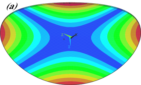
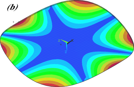
The sapphire disks were supplied by SHINKOSHA Shinkosya , Japan. The diameter of these disks was 100 mm. In order to observe the disk thickness dependence of the loss, two kinds of the disks, 0.5 and 1 mm thick disks, were prepared. The c-axis was perpendicular to the flat surface. Both sides were commercially polished (not super polished). The root mean square of the micro-roughness of the surfaces was about 0.1 nm. The coatings were made on some sapphire disks. The other uncoated disks were used to measure the Q-values without the coating. The specifications of the coating on the sapphire disks were almost the same as those of typical mirrors of the gravitational wave detectors, as follows. These disks were coated by means of ion-beam sputtering. This dielectric multilayer reflective coating consisted of 31 alternating layers of SiO2 and Ta2O5. The total thickness was 4.8 m. The optical thickness of a layer was a quarter of the wavelength, which was 1.064 m. The resulting power reflectance was estimated to be 99.99%. For investigating the effect of the details in the manufacturing process, the coating was made by two venders: the National Astronomical Observatory of Japan (NAOJ) and Japan Aviation Electronics Industry, Ltd. (JAE). The latter made the coating on the mirrors of TAMA TAMA . The JAE coating Sato was superior regarding low optical loss compared to that of NAOJ. Although the mirrors are usually annealed after the coating, only a disk with the JAE coating was annealed in this experiment. The specifications of the disks are summarized in Table 1. We measured the Q-values of the first and third modes. The resonant frequencies are given in Table 2. These frequencies with the coating were the same as those without the coating. The shapes of the first and third modes are shown in (a) and (b) of Fig. 1, respectively.
| disk thickness | heat process | coating vender | |
|---|---|---|---|
| Sample 1 | 0.5 mm | not annealed | NAOJ |
| Sample 2 | 1 mm | not annealed | NAOJ |
| Sample 3 | 1 mm | not annealed | JAE |
| Sample 4 | 1 mm | annealed | JAE |
| Sample 5 | 0.5mm | not annealed | not coated |
| Sample 6 | 1 mm | not annealed | not coated |
| thickness | first mode | third mode |
|---|---|---|
| 0.5 mm | 0.52 kHz | 1.2 kHz |
| 1 mm | 1.1 kHz | 2.5 kHz |
II.3 Measurement apparatus
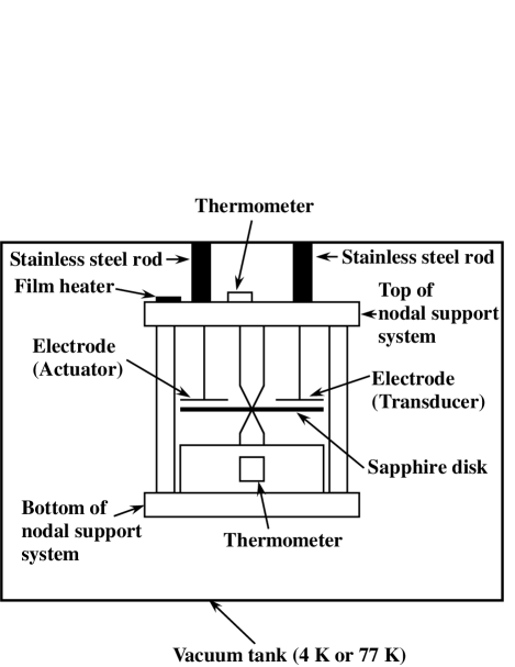
Figure 2 is a schematic side view of the measurement apparatus. We adopted a nodal support system Numata to grasp the sapphire disk. In this system, only the center of the disk was fixed (the diameter of the contact area between the sapphire disk and the support was 2 mm). Since the center is the nodal point in almost all resonant modes, the contamination of the loss of the support system, itself, was small. All parts of this support were made of copper, which has a high thermal conductivity at cryogenic temperatures. We used an electrostatic actuator to excite the resonant vibration. The ring down of this resonant motion was monitored by an electrostatic transducer transducer . The bias voltage of the actuator and the transducer was a few hundreds volts. The loss caused by this transducer was negligible because the measured Q-values were independent of the bias voltage.
The top of the nodal support system was connected by stainless-steel rods to a vacuum tank. This chamber was immersed into liquid helium or nitrogen. The pressure in the cooled chamber was between Pa and Pa in most cases. In this pressure region, the gas damping was sufficiently small because the measured Q-values with the coating did not depend on the pressure. A film heater was put on the top of the nodal support system to control the temperature between 4 K and 30 K. The two thermometers were fixed at the top and the bottom of the nodal support system instead of the sapphire disk because the thermometer possibly increases the mechanical loss. Although, in principle, the temperature of the sapphire disk was the same as that of these thermometers, we confirmed this temperature homogeneity using a dummy sapphire disk with the thermometer. This dummy disk has never been adopted to measure the Q-values.
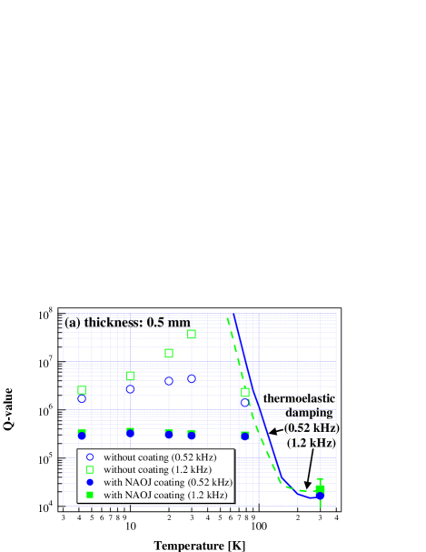
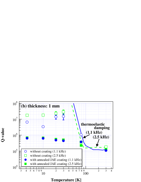
In order to check the ability of our measurement system, the typical differences between the measured Q-values with (close marks in Fig. 3) and without (open marks in Fig. 3) the coating are introduced. The thicknesses of the disks in the graphs (a) and (b) of Fig. 3 were 0.5 mm and 1 mm, respectively. The coating in the graphs (a) and (b) was NAOJ (Sample 1) and annealed JAE (Sample 4). The disk without the coating in the graphs (a) and (b) was Sample 5 and Sample 6. The circles (blue in online) and squares (green in online) are the Q-values of the first and third modes, respectively. In the low-temperature region, there was a large discrepancy between the Q-values with and without the coating Support loss . An accurate evaluation of the cooled coating loss was possible. At room temperature, the differences between the Q-values with and without the coating were small (the marks with the coating in Fig. 3 completely overlap those without the coating except for the third mode of the 1 mm thickness disk). The evaluated coating loss angles at 300 K were not precise. The reason why the differences were small was that the thermoelastic damping Zener in the sapphire disks was large at 300 K. The solid and dashed lines in Fig. 3 represent the Q-values limited by the thermoelastic damping of the first and third modes, respectively Blair .
III Results
The formula Harry ; Crooks ; Penn ; Crooks-Amaldi of the loss angle, , which is the magnitude of the loss in the coating, derived from the measured Q-values is described as Landau ; formula
| (1) |
The values, and , are the measured Q-values with and without the coating. The parameters (, , and ) are the thicknesses and Young’s moduli of the sapphire disk and the coating, respectively. These values are summarized in Table 3. The Young’s modulus of the coating is the average of those of SiO2 (Pa Sapieha ) and Ta2O5 (Pa Sapieha ; Martin ; CSIRO ) Harry ; Crooks ; Young .
| thickness | Young’s modulus | |
|---|---|---|
| sapphire disk | 1 mm or 0.5 mm | Pa |
| coating | 4.8 m | Pa |
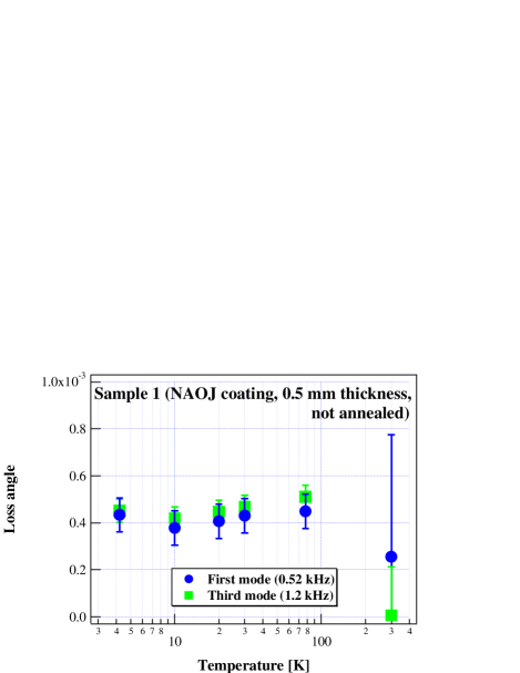
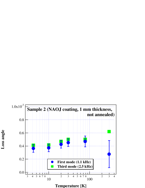
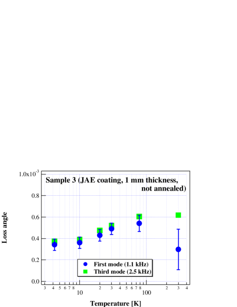
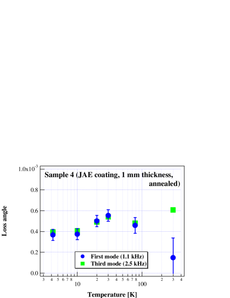
The coating loss angles derived from the measured Q-values are shown in Fig. 4 error . The circles (blue in online) and squares (green in online) represent the coating loss angles evaluated from the Q-values of the first and third modes, respectively. The four samples had similar loss angles. The loss did not strongly depend on the temperature and resonant frequency. These loss angles were . (Some loss angles at 300 K had the large error bars. The upper limits of these error bars were the order of .)
IV Discussion
IV.1 Properties of the coating mechanical loss
Figure 4 implies that the coating loss is almost independent of the temperature between 4 K and 300 K. At room temperature, the coating loss is dominated by that of Ta2O5 Penn . Thus, it is expected that the loss of Ta2O5 is also the main component of the coating loss, and is constant in the low-temperature region. The loss of the SiO2 does not change very much, either. Research showed that the loss of the fused silica film deposited by the electron beam evaporation was independent of the temperature White . The temperature dependence of these two kinds of thin SiO2 is different from that of bulk silica. Many studies (for example, Refs. Fine ; Strakna ) found that the Q-value of the bulk SiO2 has a local minimum (about ) of around 30 K.
Recently, the thermoelastic damping of the coating at room temperature was investigated theoretically Braginsky-coating ; Fejer . Since the thermoelastic damping strongly depends on temperature in general, our result suggests that the contribution of thermoelastic damping is not a large part in the loss of the coating.
The measured cold coating loss angles were not affected by a change in the frequency between 0.52 kHz and 2.5 kHz. This result suggests that the loss which depends on the frequency (for example, the thermoelastic damping) does not dominate the coating loss around this frequency region.
The coating applies a stress on the substrate of the mirror. If the strain caused by this stress causes a loss, the coating loss on the thin disk in our experiment is different from that on thick mirrors. Fortunately, this scenario is rejected because the measured coating loss on a 0.5 mm thick disk was the same as that on a 1 mm thick disk.
It was reported that annealing improves the Q-values of fused silica Fraser ; PennFS ; Numata4 . There was no such effect on the coating in our samples. This result implies that the stress does not greatly change the loss because the annealing relaxes the stress produced during the coating process.
The loss of the NAOJ coating was about the same as that of the JAE coating. Since the optical loss of the NAOJ coating was larger than that of the JAE coating, the source of the optical loss does not have a large contribution on the mechanical loss.
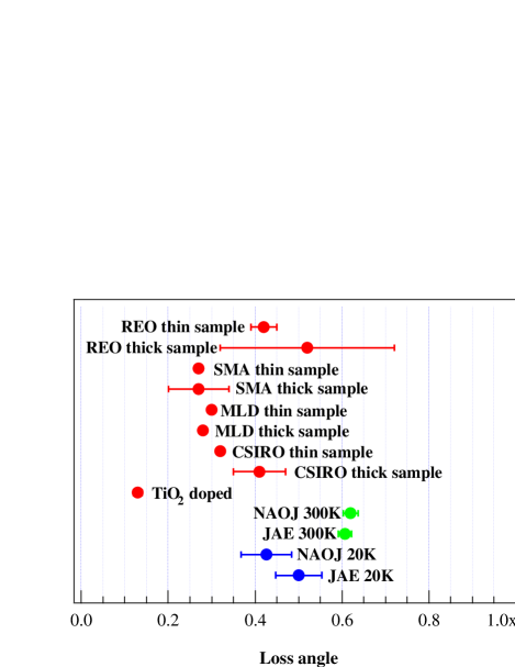
In Fig. 5, a summary of our results with those of the measurements by other groups (SiO2/Ta2O5) is listed (their references are written in the figure caption). The experiments of the other groups were at room temperature. The losses at 300 K in the coatings prepared by the various companies were on the order of . The losses of the coating made by two laboratories, NAOJ and JAE, were almost the same in the low-temperature region. Thus, it is expected that the details of the coating manufacturing processes do not greatly affect the coating loss between 4 K and 300 K. This conclusion is in contrast with that of bulk fused silica: in Ref. Numata4 , the best Q-value of the room temperature silica is about fifty-times larger than the worst one.
IV.2 Coating thermal noise in interferometric gravitational wave detector
Our experiment shows that the coating loss is almost independent of the temperature between 4 K and 300 K. This result and the formulae in Refs. Harry ; Nakagawa imply that the amplitude of the thermal noise caused by the coating loss is proportional to the square root of the temperature. The thermal noises at 20 K and 4 K are four and ten-times less than that at 300 K, respectively. Since the loss of sapphire decreases at low temperature, cooling reduces the thermal noise of the coating more modestly than that of the sapphire substrate loss. However, the other methods used to suppress the coating thermal noise (reduction of the loss, other coating material, large scale laser beam, some ideas about coating thickness) are not more effective than the cooling, as follows.
In spite of investigations concerning a reduction of the coating mechanical loss, a method used to drastically suppress the loss was not found as shown in Fig. 5. Even if TiO2 is doped Cagnoli-Amaldi , the thermal noise becomes about two-times smaller, because it is proportional to the square root of the loss angle Harry ; Nakagawa . In our measurement, annealing was not useful.
Studies about other coating materials are also in progress (for example, Nb2O5/SiO2, Ta2O5/Al2O3, Al2O3/SiO2 Sneddon-Aspen ; Harry-LSC ). An obviously better material than SiO2/Ta2O5 was not found.
Adopting a larger beam is one of the methods because the coating thermal noise is inversely proportional to the beam radius Levin ; Harry ; Nakagawa ; Yamamoto2 . When the beam becomes larger, the mirror must also be greater, owing to the diffraction loss. Because of technological limits about the scale of the mirror, the maximum beam radius is about 6 cm. Since the typical beam radius of the current km-class interferometers is about 3 cm, the reduction factor of the thermal noise is about two. Recently, a new beam profile, a flat-topped beam Mexican1 , was proposed to increase the beam scale without a large diffraction loss. The radius of this beam is 9 cm Mexican1 . The thermal noise becomes three-times smaller NumataMexican .
In Ref. Khalili , it is considered to decrease the number of the coating layers effectively (from about thirty layers to a few layers) by putting another mirror behind the end mirror. The reduction factor of this idea is about four, at most, because the thermal noise is proportional to the square root of the thickness of the coating Harry ; Nakagawa . The thermal noise of the non-periodic coating (the optical thicknesses of the layers are different from that of each other) is 1.4-times less than that of the usual coating (the optical thicknesses of the layers are the same) Pinto .
IV.3 Adequate mirror temperature for future gravitational wave detector projects
The temperature dependence of the thermal noise of the mirrors was estimated in order to evaluate an adequate mirror temperature for future interferometric gravitational wave detector projects. The thermal noise of the mirrors is dominated by the contributions of the coating and the substrate losses Yamamoto2 . The formula of the thermal noise of the coating derived in Ref. Nakagawa was used. It was supposed that the coating loss angle is independent of the frequency and . The substrate loss is the summation of the structure Bondu and thermoelastic damping Braginsky ; Cerdonio . It was assumed that the substrate Q-values are Uchiyama2 ; Rowansapphire ; Silica . The length of the interferometer baselines and the beam radius at the mirrors were 3 km and 3 cm, respectively. These were typical values.
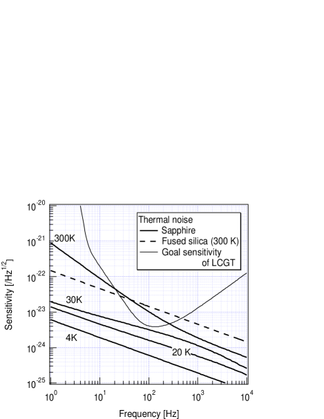
The evaluated results are given in Fig. 6. The solid thick lines represent the thermal noises of the sapphire mirrors at 300 K, 30 K, 20 K, and 4 K. The dashed line is the thermal noise of mirrors made from fused silica, which is the material of the current interferometers LIGO ; VIRGO ; GEO ; TAMA , at 300 K as a reference. The thin line shows the goal sensitivity of the LCGT project LCGT (the other future project, advanced LIGO LIGO II , has a similar goal sensitivity). The dominant loss component in each case is as follows. For the sapphire at room temperature, the thermoelastic damping and coating losses are the main component below and above 300 Hz, respectively. For the sapphire at 30 K, the coating loss and thermoelastic damping are dominant below and above 40 Hz. For the sapphire at 20 K, the coating loss is the main component, except at around 2 kHz. Only at around 2 kHz, is the contribution of the thermoelastic damping as large as that of the coating loss. For the sapphire at 4 K and fused silica, the coating loss is dominant.
The thermal noise of the sapphire mirrors at 30 K is comparable to the LCGT sensitivity. The noise at 20 K is a few-times smaller. The LCGT mirrors must be below 20 K. The thermal noise at 20 K is ten-times less than that of the current detectors (fused silica, 300 K). If the LCGT mirrors are replaced by room-temperature fused-silica mirrors, the observable distance of the chirp wave from the neutron star binary coalescence becomes about 2.7-times shorter Binary range .
IV.4 Thermal noise in laser frequency stabilization
The thermal noise of the coating will be a serious problem in the frequency stabilization of the laser. Recent research Numata-freqstab proved that the world-highest level of laser frequency stabilization using a rigid cavity is only three-times larger than the coating thermal noise. In the near future, the laser stabilization technique will achieve a fundamental physical limit, the coating thermal noise. According to our experiment, the coating thermal noise of the cavity at 4 K is ten-times smaller than that at room temperature. A cryogenic rigid cavity is one of the promising techniques to drastically improve the frequency stabilization.
V Conclusion
In order to effectively suppress the thermal noise of interferometric gravitational wave detectors, it was proposed to cool the mirrors. To evaluate the thermal noise of the cryogenic mirrors, the mechanical loss in the cooled mirrors must be investigated. However, there had been no report about the loss of the reflective coating (SiO2/Ta2O5) at low temperature until our experiment. The coating loss measurement is also an interesting topic in material science.
Our measured loss angles, , were almost constant between 4 K and 300 K. Since the room-temperature coating loss is dominated by the loss of Ta2O5, it is expected that the loss of Ta2O5 is also the main component in the low-temperature region. The loss in the ion-beam sputtered thin Ta2O5 (and also SiO2) layer is independent of the temperature. The measured coating mechanical loss was not affected by changes of the frequency, optical loss, or stress caused by the coating, and venders.
Since the coating loss does not strongly depend on the temperature, the amplitude of the thermal noise of the coating is proportional to the square root of the temperature. As far as we know, there is no more effective method to suppress the coating thermal noise than cooling. The limit of laser frequency stabilization using a rigid cavity due to the coating thermal noise decreases by an order of magnitude when the rigid cavity is cooled from 300 K to 4 K. The amplitude of the total amount of the coating and substrate thermal noises of the sapphire mirrors at 20 K is sufficiently lower than the sensitivity of even future interferometric gravitational wave detector projects, for example, LCGT.
Acknowledgements.
This work was in part supported by the 2001st year Joint Research Project (Soken/K00-3) of Sokendai (The Graduate University for Advanced Studies) and a Grant-in-Aid for Scientific Research of the Ministry of Education, Culture, Sports, Science and Technology. The MOU exchanged by three directors, Institute for Cosmic Ray Research (the University of Tokyo), National Astronomical Observatory of Japan (NAOJ) and High Energy Accelerator Research Organization, assisted this research.References
- (1) A. Abramovici et al., Science 256, 325 (1992).
- (2) C. Bradaschia et al., Nucl. Instr. and Meth. in Phys. Res. A 289, 518 (1990).
- (3) B. Willke et al., Class. Quantum Grav. 19, 1377 (2002).
- (4) M. Ando et al., Phys. Rev. Lett. 86, 3950 (2001).
- (5) K. Numata, A. Kemery, and J. Camp, Phys. Rev. Lett. 93, 250602 (2004).
- (6) T. Uchiyama et al., Phys. Lett. A 242, 211 (1998).
- (7) T. Uchiyama et al., Class. Quantum Grav. 21, S1161 (2004).
- (8) A. Giazotto and G. Cella, Class. Quantum Grav. 21, S1183 (2004).
- (9) T. Uchiyama et al., Phys. Lett. A 261, 5 (1999).
- (10) Yu. Levin, Phys. Rev. D 57, 659 (1998).
- (11) G.M. Harry et al., Class. Quantum Grav. 19, 897 (2002).
- (12) K. Yamamoto, S. Otsuka, M. Ando, K. Kawabe, and K. Tsubono, Class. Quantum Grav. 19, 1689 (2002).
- (13) N. Nakagawa, A.M. Gretarsson, E.K. Gustafson, and M.M. Fejer, Phys. Rev. D 65, 102001 (2002).
- (14) K. Yamamoto, M. Ando, K. Kawabe, and K. Tsubono, Phys. Lett. A 305, 18 (2002).
- (15) K. Numata, M. Ando, K. Yamamoto, S. Otsuka, and K. Tsubono, Phys. Rev. Lett. 91, 260602 (2003).
- (16) K. Yamamoto, S. Otsuka, Y. Nanjo, M. Ando, and K. Tsubono, Phys. Lett. A 321, 79 (2004).
- (17) E.D. Black et al., Phys. Lett. A 328, 1 (2004).
- (18) P.D. Vu, X. Liu, and R.O. Pohl, Phys. Rev. B 63, 125421 (2001).
- (19) SHINKOSHA CO., LTD., 2-4-1 Kosugaya, Sakae-ku, Yokohama, Kanagawa 247-0007, Japan (http://www.shinkosha.com/e/index.html).
- (20) S. Sato et al., Appl. Opt. 38, 2880 (1999).
- (21) K. Numata et al., Phys. Lett. A 276, 37 (2000).
- (22) The shape of the electrode of the actuator and transducer was similar to that in Ref. Uchiyama2 . These electrodes were 40 mm 40 mm. The distance between the disk and the electrodes was about 1 mm.
- (23) In this and preliminary experiments, the measured Q-values without the coating varied even though the same sample was measured. This was due to the contamination of the support system loss, probably, because this contamination strongly depends on the small difference between the center of the disk and the point grasped by the support system. Since the displacement of the first mode near the disk center is larger than that of the third mode, the Q-values of the first mode were smaller. According to our experiment, this support loss was not negligible when the measured Q-values were larger than the order of . The stastical errors of the measured Q-values with the coating were small because the coating loss was larger than the support loss (the Q-values were the order of ).
- (24) C. Zener, Phys. Rev. 52, 230 (1937); 53, 90 (1938).
- (25) D.G. Blair and J. Ferreirinho, Phys. Rev. Lett. 49, 375 (1982).
- (26) D.R.M. Crooks et al., Class. Quantum Grav. 19, 883 (2002).
- (27) S.D. Penn et al., Class. Quantum Grav. 20, 2917 (2003).
- (28) D.R.M. Crooks et al., Class. Quantum Grav. 21, S1059 (2004).
- (29) Equation (11.5) of L.D. Landau and E.M. Lifshitz, Theory of Elasticity (Pergamon, New York, 1986).
- (30) This formula is valid when the coating is negligibly thin compared with the substrate disk. The correction due to the anisotropic elasticity of the sapphire crystal and the difference between the Poisson ratio of the substrate and coating is negligible.
- (31) J.E. Klemberg-Sapieha et al., Appl. Opt. 43, 2670 (2004).
- (32) P.J. Martin et al., Proceedings of Thin Films: Stresses and Mechanical Properties IV, April 1993, Mater. Res. Soc. Symp. Proc. 308, 583 (1993).
- (33) G. Harry, in LIGO Scientific Collaboration meeting, Hanford, Washington, USA, August 2004, http://www.ligo.caltech.edu/docs/G/G040330-00/.
- (34) In Refs. Sapieha ; Martin ; CSIRO , the Young’s moduli of the thin SiO2 and Ta2O5 were measured. The Young’s modulus of the thin SiO2 Sapieha was the almost same as that of the bulk. These values were used in the previous work about the coating for the gravitational wave detection Harry ; Crooks ; Penn ; Crooks-Amaldi . It was assumed that the Young’s moduli are independent of the temperature because, in general, the temperature dependence is small (the Young’s modulus of the bulk SiO2 was almost constant Fine ).
- (35) M.E. Fine, H. Van Duyne, and N.T. Kenney, J. Appl. Phys. 25, 402 (1954).
- (36) The error bars in Fig. 4 show the statistical errors of the measured values. In the low-temperature region, these were dominated by the deviation of the support loss Support loss in most cases. The error bars do not include the differences between the substrate loss in each sapphire disk. The effect of these differences was small because the evaluated coating loss angles of the four samples in Fig. 4 were almost the same.
- (37) B.E. White, Jr. and R.O. Pohl, Phys. Rev. Lett. 75, 4437 (1995).
- (38) R.E. Strakna, Phys. Rev. 123, 2020 (1961).
- (39) V.B. Braginsky and S.P. Vyatchanin, Phys. Lett. A 312, 244 (2003).
- (40) M.M. Fejer et al., Phys. Rev. D 70, 082003 (2004).
- (41) D.B. Fraser, J. Appl. Phys. 41, 6 (1970).
- (42) S.D. Penn et al., Rev. Sci. Instrum. 72, 3670 (2001).
- (43) K. Numata et al., Phys. Lett. A 327, 263 (2004).
- (44) Research Electro-Optics, Inc., 5505 Airport Blvd, Boulder, Colorado 80301, USA (http://www.reoinc.com/).
- (45) Service des Materiaux Avances/Virgo, Lyon, France.
- (46) MLD Technologies, 2672 Bayshore Parkway, Suite 701, Mountain View, California 94043, USA (http://mldtech.com/).
- (47) Commonwealth Scientific and Industrial Research Organisation, Telecommunications and Industrial Physics, Sydney, Australia (http://www.csiro.au/).
- (48) G. Cagnoli et al., Proceedings of the 6th Edoardo Amaldi Conference on Gravitational Waves, Okinawa, Japan, June 2005, J. Phys.: Conf. Ser. 32, 386 (2006) [Institute of Physics, Bristol, U.K.].
- (49) P. Sneddon et al., in The 2003 Aspen Winter Conference on Gravitational Waves and their Detection, Aspen, Colorado, USA, February 2003, http://www.ligo.caltech.edu/docs/G/G030195-00.pdf.
- (50) G. Harry et al., in LIGO Scientific Collaboration meeting, Livingston, Louisiana, USA, March 2003, http://www.ligo.caltech.edu/docs/G/G030036-00/.
- (51) E. D’Ambrosio, Phys. Rev. D 67, 102004 (2003).
- (52) K. Numata, in The 2003 Aspen Winter Conference on Gravitational Waves and their Detection, Aspen, Colorado, USA, February 2003, http://www.ligo.caltech.edu/docs/G/G030213-00.pdf.
- (53) F.Ya. Khalili, Phys. Lett. A 334, 67 (2005).
- (54) J. Agresti et al., in LIGO Scientific Collaboration meeting, Hanford, Washington, USA, August 2005, http://www.ligo.caltech.edu/docs/G/G050363-00/.
- (55) F. Bondu, P. Hello, and J.-Y. Vinet, Phys. Lett. A 246, 227 (1998).
- (56) V.B. Braginsky, M.L. Gorodetsky, and S.P. Vyatchanin, Phys. Lett. A 264, 1 (1999).
- (57) M. Cerdonio, L. Conti, A. Heidmann, and M. Pinard, Phys. Rev. D 63, 082003 (2001).
- (58) S. Rowan et al., Phys. Lett. A 265, 5 (2000).
- (59) A. Ageev, B.C. Palmer, A. De Felice, S.D. Penn, and P.R. Saulson, Class. Quantum Grav. 21, 3887 (2004).
- (60) P. Fritschel, Proceedings of the SPIE meeting Gravitational-Wave Detection (4856-39), Waikoloa, Hawaii, 2002, edited by P. Saulson and M. Cruise (International Society for Optical Engineering, WA, 2002), p.282.
- (61) L.S. Finn and D.F. Chernoff, Phys. Rev. D 47, 2198 (1993).