Frequency-Dependent Squeeze Amplitude Attenuation and Squeeze Angle Rotation by Electromagnetically Induced Transparency for Gravitational Wave Interferometers
Abstract
We study the effects of frequency-dependent squeeze amplitude attenuation and squeeze angle rotation by electromagnetically induced transparency (EIT) on gravitational wave (GW) interferometers. We propose the use of low-pass, band-pass, and high-pass EIT filters, an S-shaped EIT filter, and an intra-cavity EIT filter to generate frequency-dependent squeezing for injection into the antisymmetric port of GW interferometers. We find that the EIT filters have several advantages over the previous filter designs with regard to optical losses, compactness, and the tunability of the filter linewidth.
I Introdcuction
The gravitational wave (GW) community is currently exploring strategies to overcome the quantum limited sensitivity of next generation GW interferometers. One of the most promising techniques is the injection of squeezed fields into the antisymmetric (dark) port of the GW interferometers Caves (1981). Future GW interferometers will use higher circulating power to reduce shot noise at high frequencies, but this increase in power makes the radiation pressure noise significant at low frequencies. The effect of the radiation pressure noise is to ponderomotively squeeze the optical fields with a frequency dependent (FD) squeeze angle due to the FD response of the test masses Kimble et al. (2002). This presents difficulty in injecting squeezed states into the interferometer because the squeeze angle of the squeezed state source must be matched to the ponderomotive squeeze angle. Squeezed state sources are generally frequency independent, but the desired angle may be produced by using optical cavities placed between the squeezed state source and the interferometer as filters. Both filters that rotate the squeeze angle to match the ponderomotive squeeze angle Kimble et al. (2002); Harms et al. (2004) and filters that attenuate the anti-squeezing in a desired band Corbitt et al. (2004) have been proposed. The attenuation filters operate on the principle that the squeezed state with a frequency independent squeeze angle has beneficial effects over some frequency band, but harmful effects over other frequency bands, and those harmful effects can be mitigated by introducing a FD optical loss. The previously proposed cavity filters Kimble et al. (2002); Corbitt et al. (2004), while producing the desired effects, are difficult to build because they require cavities with narrow linewidths comparable to the bandwidth of the interferometer (), which require either kilometer-scale cavities, or high finesse cavities. For squeeze angle rotation, high finesse cavities are somewhat undesirable due to high optical losses. For example, assuming a round trip optical loss of , a cavity would have to be nearly to maintain an effective loss of or less. In this paper, we propose alternative filter designs based on electromagnetically induced transparency (EIT) media, for both attenuation and rotation, that do not require long or high finesse cavities, and also have increased tunability.
Several properties of EIT media make them a potentially advantageous alternative to ultralow-loss or km-scale optical cavities. First, EIT media typically have narrow transmission resonance linewidths; the narrowest linewidth reported is Hz in a paraffin coated cell with 85Rb as the EIT medium Budker et al. (1999). The EIT media can also be very compact, with typical lengths of cm. Second, the resonance linewidth may be adjusted in non-invasive ways, by changing the atomic density Lukin et al. (1997) or drive field intensity Harris (1997), to optimize the filtering. Altering the linewidth of an optical cavity, on the other hand, usually requires changing the transmission of the mirrors or the macroscopic cavity length. Other variable reflectivity techniques, e.g., three-mirror cavities, are possible, but issues of fringe control, scattered light and mode mismatch are compounded in such systems. Third, EIT media can be nearly 100% transmissive for the probe field Xia et al. (1999); Braje et al. (2003). Fourth, mode matching of the spatial mode of the squeezed (probe) beam to that of the EIT is not critical, as it is for an optical cavity, where mode mismatch can be a significant source of optical loss 111See, Fig. 5 of Ref. Xia et al. (1999), e.g., where the authors showed that the probe field (in our case a squeezed state) need not be modematched to drive laser spatial mode, but be just contained within this mode.. Fifth, EIT media have also been shown to preserve squeezed states in transmission Akamatsu et al. (2004). These reasons lead naturally to consideration of using EIT for squeezed state filters.
The paper is organized as follows: In Section II we develop the theoretical formulation of how an EIT medium gives rise to squeeze state attenuation and squeeze angle rotation, and we derive the quadrature noise at the output of an example gravitational wave interferometer for a generic input squeezed state; in Section III we analyze three different cases of EIT filtering of the input squeezed state and derive the quantum noise limited sensitivity of the GW interferometer for each case; we summarize our findings in Section IV.
II Theory
In this Section we relate the general properties of the EIT medium, as described by a complex transmission coefficient, to the propagation of the squeezed state, in terms of rotation and attenuation. We then apply this formulation to the output of a GW interferometer.
II.1 Squeeze amplitude attenuation and squeeze angle rotation by EIT
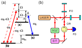
The energy level scheme for one photon resonant EIT is shown in Figure 1(a). Using the parameters defined in Figure 1, the EIT transmission as a function of the sideband frequency, , is given by
| (1) |
where is the wave vector of the probe field through the EIT medium. For most cases, it is reasonable to assume that the susceptibility of the medium and , then the wave vector can be written as
| (2) | |||||
In the frequency domain, substituting Eq. (2) into Eq. (1) and moving into the rotating frame of the probe field, , with frequency, Collett and Gardiner (1984), we find the EIT transmission at sideband frequencies, ,
| (3) |
where
| (4) | |||||
| (5) |
Here and are the real and imaginary parts of . is responsible for phase shift and is responsible for signal strength attenuation.
When the input field, , is injected into an EIT medium, the output field, , and its adjoint, , are given in terms of and its adjoint, , by
| (6) | |||||
| (7) |
where is the EIT absorption coefficient such that
| (8) |
and is a vacuum field coupled in by the absorption loss. and satisfy the commutation relations
| (9) |
and all others vanish (similarly for and ). In the two-photon representation, the amplitude and phase quadratures of are defined as
| (10) | |||||
| (11) |
respectively (similarly for and ). We find the amplitude and phase quadrature fields of the output, in compact matrix form, to be
| (12) |
where we use the two-photon matrix representation
| a | (15) |
for the operator, (and similarly for and ), and
| (20) |
is a matrix representing propagation through the EIT medium. M comprises an overall phase shift, , rotation by angle, , and attenuation by a factor, . Here we have defined
| (21) |
and performed a unitary transformation on v, such that
| (24) | |||||
and behaves as ordinary unsqueezed vacuum. For symmetrical lineshapes with respect to the carrier, , and therefore vanishes, giving no quadrature angle rotation, but attenuating the signal strength. For asymmetrical lineshapes, nonzero gives quadrature angle rotation.
II.2 Application to GW interferometers
For a conventional GW interferometer with arm lengths and mirror masses , the Fourier transform of the optical noise in the GW strain signal when a (EIT-filtered) squeezed field b is injected into the dark port is given by Kimble et al. (2002)
| (25) |
and
| (26) |
is the effective coupling constant that relates motion of the mirrors to the output signal. Here is the linewidth of the arm cavities (typically Hz), is the carrier frequency of the incident laser light, and is the laser power at the beam-splitter.
Assuming no losses other than those associated with the EIT filter, a squeezed state with squeeze factor and squeeze angle is injected into the antisymmetric port of the GW interferometer through the EIT filter [see Figure 1(b)]. The input angle may be arbitrarily chosen by microscopic variations in the distance between the squeezed state source and the interferometer. The spectral density of the noise at the output of the GW interferometer is then
| (27) |
where . Here
| (28) |
is the effective ponderomotive squeeze angle of the interferometer, and the noise in the anti-squeezed and squeezed quadratures, and , respectively, is given by
| (35) | |||||
| (38) |
III EIT filters
In this section, we propose three kinds of EIT filters: (i) low-pass, band-pass, and high-pass squeeze amplitude attenuation filters, (ii) an S-shaped filter as a frequency-dependent squeeze angle rotator, and (iii) an intra-cavity EIT filter as a frequency-dependent squeeze angle rotator.
To obtain expressions for the EIT transmission , it is useful to use the following formulae for EIT susceptibility, Mikhailov et al. (2004); Taichenachev et al. (2003)
| (39) | |||||
| (40) | |||||
where is the EIT resonance linewidth and the coefficients , and depend on the intensity and detuning, , of the drive field. The first term on the right hand side in Eq. (39) corresponds to asymmetric phase dependence on the two-photon detuning and the second term is responsible for symmetrical Lorentzian dependence. Similarly, the first term in Eq. (40) corresponds to symmetrical dependence on the absorption coefficient of the EIT medium, the second term indicates asymmetric absorption, and the third term corresponds to broadband absorption in the medium. Inserting Eqs. (39) and (40) into Eqs. (4) and (5), we get explicit expressions for and , which are used calculate the noise at the output of the GW interferometer , as described in Section II.2.
III.1 Squeeze amplitude attenuation filters
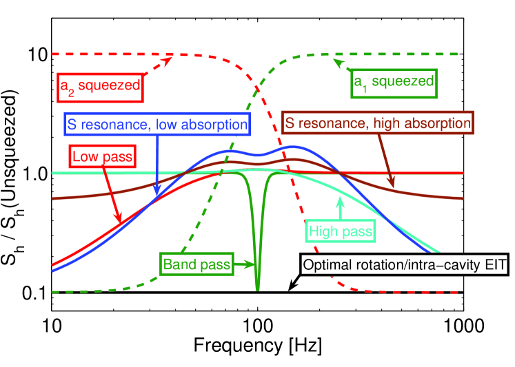
If we take , , , and Harris (1997), then for and for , and we obtain a symmetric EIT transmission line with and . This can be used as a squeeze amplitude filter that retains squeezing at low frequencies, but causes ordinary (unsqueezed) vacuum to replace the anti-squeezed noise at higher frequencies that are outside the EIT bandwidth. This is equivalent to the low-pass filters proposed in Corbitt et al. (2004). Similarly, buffer gas induced electromagnetically induced absorption (BGIEIA) Mikhailov et al. (2004) may be used as a high-pass filter. BGIEIA is similar to EIT, with a narrowband absorption resonance instead of the transmission resonance of EIT. High-pass filtering with BGIEIA can be realized with parameters , , , and , such that for and for . A combination of two EIT resonances, equally detuned from the carrier (obtained by Zeeman splitting Wynands and Nagel (1999)), serves as a band-pass filter. In Figure 2 the effect of low-pass, band-pass, and high-pass EIT filters on the noise spectral density of a GW interferometer are shown by the curves labelled “low pass” (red), “band pass” (dark green), and “high pass” (cyan), respectively. The noise spectra are normalized by the noise spectral density of a conventional interferometer with no squeezed state injection, which corresponds to the unity in Figure 2. In each case, the harmful effects of squeezing with a constant squeeze angle are reduced.
III.2 Squeeze angle rotation filters
The filters discussed so far only provide attenuation of the squeezing, they do not produce any squeeze angle rotation. We now introduce two cases of EIT that also produce squeeze angle rotation.
III.2.1 S-shaped EIT filter
In principle, optimum squeeze angle rotation, corresponding to , can be obtained with an asymmetrical – or S-shaped – EIT filter, realized under conditions similar to BGIEIA with parameters , , and . In this case, the noise spectral density can be optimized over most frequencies. However, as is evident from the curves labelled “S resonance” (brown and blue) in Figure 2, the improvement is small because of the high off-resonance losses associated with the coefficient ; optimization would require setting . The noise is decreased at both high and low frequencies, but worsened in the middle of the band due to two effect. First, the imbalance in absorption () between the upper and lower sidebands required to obtain the squeeze angle rotation causes the quadratures to be mixed and the noise may be higher than shot noise. Second, the imperfect squeeze angle rotation, , couples in noise from the anti-squeezed quadrature.
III.2.2 Intracavity EIT
Placing an EIT medium in an optical cavity narrows the cavity linewidth Müller et al. (1997); Lukin et al. (1998). We consider a symmetric EIT transmission resonance, such as the one used for our low-pass filter, with a large linewidth , such that , , and in the frequency band of interest (100Hz). This configuration may be understood in terms of the group velocity of the light through the EIT medium
| (41) |
We may then express
| (42) |
where is the effective cavity length. The EIT medium serves as an additional delay line inside the cavity. A group velocity as low as 8 m/s in a 12 cm long Rb vapor cell was demonstrated by Budker et al. Budker et al. (1999), giving an effective length on the order of . To use intra-cavity EIT as a squeeze angle rotation filter, we must detune the cavity (but not the EIT medium) from the carrier. For this case, the rotation arises from the detuned cavity, similar to the filters in Ref. Kimble et al. (2002), and not from the EIT. The EIT acts only to modify the resonant linewidth of the cavity by increasing its effective length. To achieve the required Hz linewidth for the filter, we use an EIT with a large effective length, combined with a short cavity. The performance of this cavity is essentially identical to that of an isolated cavity with no EIT and length equal to , and may achieve optimal squeeze angle rotation with a much smaller optical loss than a traditional cavity of the same linewidth with the same real (not effective) length, giving improved GW interferometer sensitivity at all frequencies. We note that is a reasonable approximation because of the narrowed linewidth of the system (, where is the transmission of the cavity input mirror). Detailed calculations show that the effective loss of the system may even be reduced by placing the EIT in a shorter cavity for some parameter choices. The broadband reduction of noise from such an intra-cavity EIT filter is shown in the curve labelled “intra-cavity EIT” (black) in Figure 2, and corresponds exactly to the much coveted optimal frequency-dependent squeezing of Ref. Kimble et al. (2002).
IV Conclusions
In summary, we have shown that frequency-dependent squeeze
amplitude attenuation and squeeze angle rotation by EIT can
improve the sensitivity of GW interferometers. We find that the
EIT filters perform the same functions as previous filter designs,
but may be easier to implement, due to lower optical losses,
compactness, and easy linewidth tunability. While suitable EIT
media for the 1064nm transition – the wavelength of laser light
in present GW interferometers – have not yet been identified, we
note that the ideal wavelength for future GW interferometers may
well be determined by availability of high-power lasers,
low-absorption optical materials, squeezed light sources, high
quantum efficiency photodetectors, and perhaps EIT filters.
V Acknowledgment
We would like to thank our colleagues at the LIGO Laboratory, especially C. Wipf. We are grateful for valuable comments from I. Novikova at Harvard University, A. B. Matsko at Jet Propulsion Laboratory, P. K. Lam and K. McKenzie at Australian National University, and G. Müller at University of Florida. We gratefully acknowledge support from National Science Foundation grants PHY-0107417 and PHY-0457264.
References
- Caves (1981) C. M. Caves, Phys. Rev. D 23, 1693 (1981).
- Kimble et al. (2002) H. J. Kimble, Y. Levin, A. B. Matsko, K. S. Thorne, and S. P. Vyatchanin, Phys. Rev. D 65, 022002 (2002).
- Harms et al. (2004) J. Harms, R. Schnabel, and K. Danzmann, Phys. Rev. D 70, 102001 (2004).
- Corbitt et al. (2004) T. Corbitt, N. Mavalvala, and S. Whitcomb, Phys. Rev. D 70, 022002 (2004).
- Budker et al. (1999) D. Budker, D. F. Kimball, S. M. Rochester, and V. V. Yashchuk, Phys. Rev. Lett. 83, 1767 (1999).
- Lukin et al. (1997) M. D. Lukin, M. Fleischhauer, A. S. Zibrov, H. G. Robinson, V. L. Velichansky, L. Hollberg, and M. O. Scully, Phys. Rev. Lett. 79, 2959 (1997).
- Harris (1997) S. E. Harris, Phys. Today 50, 36 (1997).
- Xia et al. (1999) H. Xia, A. J. Merriam, S. J. Sharpe, G. Y. Yin, and S. E. Harris, Phys. Rev. A 59, R3190 (1999).
- Braje et al. (2003) D. A. Braje, V. Balić, G. Y. Yin, and S. E. Harris, Phys. Rev. A 68, 041801(R) (2003).
- Akamatsu et al. (2004) D. Akamatsu, K. Akiba, and M. Kozuma, Phys. Rev. Lett. 92, 203602 (2004).
- Collett and Gardiner (1984) M. J. Collett and C. W. Gardiner, Phys. Rev. A 30, 1386 (1984).
- Mikhailov et al. (2004) E. E. Mikhailov, I. Novikova, Y. V. Rostovtsev, and G. R. Welch, Phys. Rev. A 70, 033806 (2004).
- Taichenachev et al. (2003) A. V. Taichenachev, V. I. Yudin, R. Wynands, M. Stahler, J. Kitching, and L. Hollberg, Phys. Rev. A 67, 033810 (2003).
- Wynands and Nagel (1999) R. Wynands and A. Nagel, Appl. Phys. B 68, 1 (1999).
- Müller et al. (1997) G. Müller, M. Müller, A. Wicht, R.-H. Rinkleff, and K. Danzmann, Phys. Rev. A 56, 2385 (1997).
- Lukin et al. (1998) M. Lukin, M. Fleischhauer, M. Scully, and V. L. Velichansky, Opt. Lett. 23, 295 (1998).