Results from the LISA Phase Measurement System Project777ESA/ESTEC contract 15658/01/NL/EC, Technical Officer Alberto Resti
Abstract
This article presents some of the more topical results of a study into the LISA phase measurement system. This system is responsible for measuring the phase of the heterodyne signal caused by the interference of the laser beams between the local and far spacecraft. Interactions with the LISA systems that surround the phase measurement system imply additional non-trivial requirements on the phase measurement system.
1 Introduction
Systems Engineering & Assessment Ltd., in association with the Universities of Birmingham and Glasgow, has carried out a study into the Phase Measurement System that will be required to measure the optical heterodyne signals on board the LISA spacecraft. The LISA mission forms one of the most ambitious space missions ever conceived, where many difficulties have to be overcome using novel techniques, and tightly coupled systems. The interactions between the various LISA systems puts very strong requirements on the various systems, and the Phase Measurement System in particular.
This reports summarises some of the more topical drivers for the design of the Phase Measurement and associated systems.
2 Time Delay Interferometry
One of the strongest drivers on the Phase Measurement System design is the requirement to cancel laser phase noise by approximately seven orders of magnitude. The baseline method for cancelling laser phase noise is Time Delay Interferometry (TDI) [1]. This technique cancels the phase noise through combinations of time delayed measurements. To give an example of how these cancellations occur consider a simplified version of the TDI1 X variable. This is illustrated graphically in the Rabbit Eared Diagram Figure 1 [2].
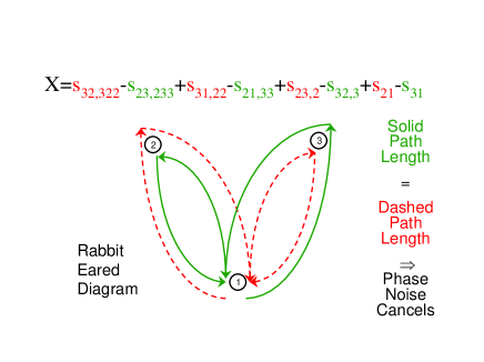
The phase measurements give the difference in phase between the local laser at the current time and the distant laser at a prior time. By combining with the phase measurements at another spacecraft, taken at earlier times the distant laser phase noise is cancelled, at the expense of introducing phase noise at earlier times at yet another laser. By combining two phase streams, shown as the solid and dashed lines in Figure 1, after four measurements each the phase noise for the two data steams on spacecraft 1 are identical. This means that subtracting the two streams the X variable cancels the laser noise. In the X variable the two data streams are distinguished by the sign of each term, either summing or subtracting.
Effectively the TDI variables construct an equal arm interferometer. Instead of the laser beams being reflected TDI utilises phase measurements to construct the two equal length arms. This means that the intuition developed for equal arm interferometers is equally applicable to LISA with TDI.
In particular the difference in arm lengths introduces the laser frequency noise into the TDI variable, in terms of the Laplace transform:
| (1) |
where is the laser frequency noise, and the time difference between the arm lengths. For laser frequency noise at the level of this implies that the arm lengths need to be equal within 10m or 33ns in order for the phase noise to be kept below . This requirement also applies to the synchronisation of the various phase measurements inside the TDI variables.
This has several implications on the phase measurement system:
-
•
The phase measurements time stamp need a fidelity of .
-
•
The phase measurements on independent spacecraft needs to be synchronised to .
-
•
Multiple Phase Measurement Systems will be required per heterodyne, to ensure than several phase measurements can be made on a single heterodyne, but with precise and varying time separation.
The synchronisation of phase measurements on distinct spacecraft is especially onerous, as it apparently requires an entirely new LISA system that synchronises the spacecraft, either:
-
•
Absolutely synchronising the spacecraft clocks to and knowledge of the spacecraft separation to .
-
•
Or synchronising the phase measurements along null light like vectors between the spacecraft.
Although recent work [3] suggests that interpolation between phase measurements may also provide the required synchronisation without the need for a Synchronisation System.
3 Decimation
A typical phase measurement system forms an average of the phase difference over the phase measurement time period.
| (2) |
Where measurements take place at the time intervals for . Considering equation 2 as a continuous time process the suppression of phase noise falls as in the high frequency limit. For laser frequency noise at the level of this gives the phase measurement process noise which falls as:
| (3) |
This only falls slowly with increasing frequency (), and this implies significant aliasing of the noise into the decimated phase measurement. In order for the noise to be below at frequencies above the decimation Nyquist Frequency (), and for laser frequency noise at the level , the sampling rate has to be in excess of . Such a high rate is infeasible for a space mission such as LISA because of the unacceptably high telemetry rate it would imply. This has the possible implications:
-
•
The aliasing of phase noise into the phase measurement in equation 2 although severe, is linear in the laser phase noise. This means that at distinct phase measurements, e.g. on separate spacecraft, that the aliasing of phase noise is identical for all laser phase noise. Hence the aliasing of phase noise just increases the level of the noise, and does not invalidate the TDI methodology. So it is possible to accept some aliasing of the phase noise, but at the expense of increasing the level of synchronisation needed to cancel the noise.
-
•
The phase measurement process needs to be designed to significantly suppress the high frequency noise to avoid aliasing problems. This can be achieved using analogue filters, digital filters on the phasor signal (such as Fourier Transform windowing functions), and digital filters on the extracted phase. This significantly increases the design complexity of the digital system. In order to avoid the aliasing of noise the signal needs to be over sampled, this implies overlapping digital processing, as for example is familiar when windowing is used in FFT applications.
It is expected that a combination of these will be ultilised in LISA, and its is necessary to ensure that the LISA methodology is compatible.
4 Phase Noise Measurements
The level of laser phase noise has another major impact on the phase measurement system, in that the heterodyne signal being measured is intrinsically noisy. The Phase Measurement System must express this noise in a form where it can be cancelled by phase differences used in TDI [5, 6, 7].
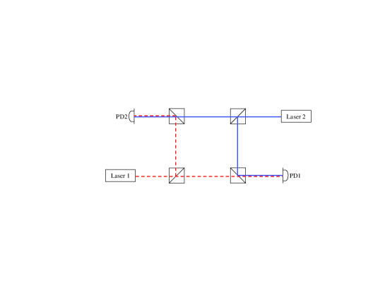
The simplest configuration that illustrates the difficulty is shown in Figure 2. In this gedankenexperiment all components are mounted on a stable optical bench; the lasers each have independent phase noise. The two photodiodes each measure a noisy signal, caused by the laser phase noise. However the phase difference between the photodiodes is a property of the optical bench and hence should be constant.
This can be understood as arising because two independent frequencies of phase noise contribute to noise at the measurement frequency, both baseband and at twice the frequency. The noise at baseband cancels in differences between phase measurements, as is required by TDI; however the noise at twice the frequency is more complex. Consider a signal with a small amount of phase noise at twice the main frequency:
| (4) |
The phase noise is responsible for a second term at exactly the heterodyne frequency, i.e. it can not be removed from the signal. If this signal is measured by a phase meter which converts the heterodyne to a phasor, e.g. a Fourier Transform based phase measurement techniques, then:
| (5) |
Unfortunately the term does not cancel in phase differences. Consider the phase measurement between two heterodynes with phases and , with common phase noise. The phasor for the measured phase difference is:
| (6) |
The is the expected phase measurement, but the term produces an unsupressed error. This error is zero when or , but not in general.
To further illustrate this noise source a numerical simulation of the gedankenexperiment shown in Figure 2 has been carried out. The laser frequency noise has been modelled as:
| (7) |
as a stabilised NPRO laser, with the knee at Hz given by the bandwidth of the piezo electric control crystal. For such a laser the phase noise only falls below for Hz. This is suggestive that the heterodyne frequency needs to be in excess of Hz. In the simulation the phase has been measured by digitisation of the heterodyne, followed by DFT/FFT, with the various parameters set as:
| (8) |
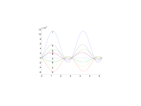
The simulation results are shown in Figure 3. To interpret this figure consider if the properties of optical bench are such that a phase difference of rad is expected. The measured phase difference differs for in subsequent phase measurements as shown on the vertical line and labelled . The variation in phase is at level of rad. As a power spectral density this corresponds , as expected from the analytic calculation. If the optical bench had a different phase offset between the two measurements then the magnitude of the phase error varies, as shown along the axis of Figure 3 for the identical phase noise from the lasers. It can be seen that there is no phase error when the phase difference is a multiple of .
At first inspection this does not seem to be a difficulty for LISA, as typical heterodyne frequencies will be in excess of 1MHz, well beyond the frequency found above. However the problems occur for the phase measurement parameters (8), where the digitisation rate of MHz is beyond that possible with space qualified hardware. The phase measurement systems considered under the LISA PMS contract have circumvented this by electrically downconverting the heterodyne to a lower frequency, before digitisation. However as the heterodyne is measured at lower frequency than the signal on the photodiode, the noise that enters at the phase measurement is sensitive to phase noise at twice the measurement frequency. This phase measurement frequency is typically well below the Hz frequency at which the laser phase noise becomes significant.
Similar sources of noise that originate at twice the heterodyne frequency have independently also been recently identified [8].
5 Phasor processing
The difficulty is caused because a sinusoidal heterodyne lacks the definition required. Specifically the maximum and minimum of a sinusoid show little sensitivity to phase, whilst the zero crossing shows maximal sensitivity to phase. This in turn means that phase measured from a sinusoid is most sensitive to phase noise during the zero crossings of the sinusoid. The difficulty can be cured if the quadrature component of the heterodyne can be obtained as well as the in-phase component. This spreads the phase information evenly in the signal. Mathematically this means that the full phasor representation, including imaginary part, can be constructed for the heterodyne:
| (9) |
The phasor extracted from this signal has the term missing:
| (10) |
and hence only the baseband phase noise is present, which is successfully cancelled via TDI.
So how can the in-phase and quadrature components of the heterodyne be physically constructed? This is traditionally achieved during downconversion of the heterodyne from higher frequency, simultaneously downconverting against both an in-phase and quadrature signals. For example if the LISA heterodyne is originally at say 20MHz, but is downconverted to 10kHz for measurement, this downconversion can introduce the in-phase and quadrature components.
This is not the only downconversion in the LISA laser interferometry. The interference of the two lasers beams on the photodiode forms an optical downconversion between the two beams, from the optical frequency down to the electrical heterodyne frequency. This down conversion can also be used to generate in-phase and quadrature signals [4], using the following method:
-
•
Using quarter wave plates circularly polarise one beam, and linearly polarise the other. The two linear polarisations of the circularly polarised light are in quadrature, whilst the two linear polarisations (at ) to the linearly polarised light are in phase.
-
•
Separately interfere the two linear polarisations of each beam (at to the linearly polarised light). This can be achieved using the two outputs of a polarising beam splitter.
-
•
The two heterodynes formed from the two polarisations are in quadrature.
Comparing the optical to electrical in-phase and quadrature generation the following comments can be made:
-
•
The optical method requires a more complicated optical bench design.
-
•
Although the optical method splits the laser beams, this does not lead to an increase in shot noise, as both the halves each enter in the full phase measurement.
-
•
The electrical method probably suffers from the problem of phase noise at twice the heterodyne. However the relevant frequency is twice the heterodyne on the photodiode. Depending on the level of phase noise this may force the heterodyne frequency to an unacceptably high value.
-
•
The optical method also has contributions from phase noise but at twice the optical frequency, i.e. , at which the laser phase noise will be insignificant.
During the study the preference has been for the electrical generation of the in-phase and quadrature signals. However a full tradeoff is required before a final decision is made.
6 Conclusions
This ESA funded study by SEA and its team into the Phase Measurement System for LISA has demonstrated many previously unexpected interactions between LISA systems. These interactions impose additional requirements on the Phase Measurement System that significantly complicate the design of LISA. A few of the difficulties have been summarised in this article; more details can be found in [6, 7]. None of the difficulties seem unsurmountable, provided they are taken into account sufficiently early in the system detailed design.
References
References
- [1] “Time-Delay Interferometry for LISA”, Massimo Tinto, F.B.Estabrook and J.W.Armstrong. Phys. Rev. D, 65, (2002) 082003.
- [2] David Summers, “Algorithm tradeoffs,” oral presentation, 3rd progress meeting of the LISA PMS Project. ESTEC, NL, February 2003.
- [3] “Postprocessed time-delay interferometry for LISA”, D.A.Shaddock, B.Ware, R.E.Spero, and M Vallisneri Phys. Rev. D, 70, (2004) 081101.
- [4] David Summers, “LISA Tradeoffs - Digital Signal Processing”, Nov 2003, SEA/03/TN/4276, TN-SEA-LI-1029, issue 1. Output of the LISA PMS ESA/ESTEC contract 15658/01/NL/EC.
- [5] David Summers, “Common Mode Phase Noise Cancellation Difficulties at High Frequency on LTP”, SEA/04/TM/4419, issue 1. Output of the LISA PMS ESA/ESTEC contract 15658/01/NL/EC.
- [6] David Summers, “LISA PMS Project Task 3 Report”, June 2004, SEA/03/TR/4331, TR-SEA-LI-1035, issue 1, and references therein. Output of the LISA PMS ESA/ESTEC contract 15658/01/NL/EC.
- [7] David Summers, “LISA PMS Project Task 4 Report”, January 2004, SEA/03/TR/4339, TR-SEA-LI-1036, issue 1, and references therein. Output of the LISA PMS ESA/ESTEC contract 15658/01/NL/EC.
-
[8]
“Candidate LISA Frequency (Modulation) Plan”
W.Folkner et.al.,
Presentation at the 5th International LISA Symposium.
http://www.rssd.esa.int/SP/SP/docs/LISASymposium/W.Folkner/Folkner-freq.pdf