Direct Observation of Broadband Coating Thermal Noise
in a Suspended Interferometer
Abstract
We have directly observed broadband thermal noise in silica/tantala coatings in a high-sensitivity Fabry-Perot interferometer. Our result agrees well with the prediction based on indirect, ring-down measurements of coating mechanical loss, validating that method as a tool for the development of advanced interferometric gravitational-wave detectors.
There are numerous large-scale interferometer projects around the world aimed at initiating gravitational-wave astronomy, including LIGO [1], GEO [2], VIRGO [3], TAMA [4], and ACIGA [5]. The astrophysical reach of these detectors depends strongly on their strain sensitivity, and even modest reductions in the noise level of a detector can lead to dramatic increases in the number of observed events per year [6]. For this reason, it is important not only to reduce the total noise in an interferometric gravitational wave detector to its fundamental limits, but also to understand those fundamental limits and to reduce them as much as possible.
Broadband thermal noise in both the mirror substrates and dielectric coatings is expected to limit the sensitivity of interferometric gravity-wave detectors in their most sensitive frequency bands, in a region that is potentially of the greatest astrophysical interest [7]. Bulk thermal noise can be reduced by using mirror substrates with extremely low mechanical losses, to the point that coating thermal noise is now expected to be a dominant fundamental noise source in advanced detectors [8, 9, 10].
Since thermal fluctuations are related to mechanical losses via the fluctuation-dissipation theorem [11, 12], the thermal noise in an interferometer can be calculated if one has sufficient knowledge of the various intrinsic mechanical losses in the system [13, 8]. Unfortunately, coating thermal noise is considerably more difficult to model than bulk thermal noise, owing to the complex, multi-layer structure of dielectric coatings. Furthermore, it has been shown that the mechanical and thermal properties of thin films in general can differ markedly from the bulk properties of identical materials [14].
To investigate the fundamental measurement limits imposed by coating and bulk thermal noise, we constructed a small-scale suspended interferometer to directly measure thermal noise. We used fused-silica test masses and low-loss coatings with a fairly large laser spot size, so the thermal noise was as low as practical, and thus pertinent to the investigation of thermal noise in gravitational wave detectors.
1 The instrument
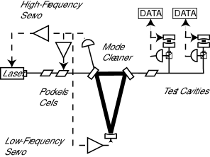
Figure 1 shows a schematic of the interferometer. Two test cavities with identical lengths and finesses were made from four identical, independent, suspended mirrors. Three other suspended mirrors made up a mode cleaner, which provided both spatial filtering and, through an active feedback system, frequency stabilization for the laser. The test cavities were locked to the resulting filtered and stabilized beam by actuating on their output (end) mirrors. Residual laser frequency noise was partially removed by differencing matched data streams from the two cavities.
Each suspended optic was supported by a single loop of fine steel music wire and actuated on by means of a magnet-coil system, with the magnets being attached to the backs of the mirrors. Each suspended optic was also actively damped using analog feedback electronics. Test mirrors were made from high-purity, synthetic fused silica (Corning 7980). All optics were superpolished on their faces for optical performance and polished on their barrels to improve mechanical ’s. High-reflectivity coatings were multilayer dielectric stacks provided by Research Electro-Optics [15].
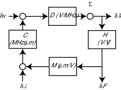
The test cavities were locked to the stabilized laser beam using the Pound-Drever-Hall method [16, 17]. Figure 2 shows a block diagram of the servo used for locking the arm cavities and for acquiring data. Here represents the Pound-Drever-Hall discriminant, the electronic transfer function of the servo filter, the transfer function of the actuation system, and is a conversion factor between the length of the cavity and the laser frequency . The equivalent length noise of the cavities was obtained from the measured voltage by
We had to know the frequency-dependent transfer functions of the blocks in Figure 2 in order to convert the measured voltage noise into an equivalent length noise . The electronic transfer function was specified in the design of the instrument and verified by direct measurements. The mirror response was measured two independent ways: First, we constructed a Michelson interferometer with the suspended mirror forming the end mirror of one arm. By driving the mirror through multiple fringes, we were able to calibrate its response. Second, we drove the PZT input of the laser to introduce a known frequency fluctuation into the beam through the mode cleaner with the system in lock. We then measured the feedback voltage at frequencies well below the unity-gain frequency, which allowed us to determine . We calibrated using a fixed-length Fabry-Perot cavity, and our measured PZT response agreed with the manufacturer’s specifications. Both methods of calibration gave the same value for , within experimental uncertainties.
The Pound-Drever-Hall discriminant was also measured two different ways. First, we measured the slope of the error signal at the resonance point, using the sidebands as a frequency reference, as the system was swept through resonance with no feedback engaged. Second, we locked the arm cavities and measured the total open-loop transfer function using a summing junction ( in Figure 2). Using known values for , , and , we then fit a theoretical prediction of to this measurement, with as an adjustable parameter. Both determinations of agreed to within experimental uncertainties. This open-loop transfer function measurement and calibration were performed separately each time the interferometer was locked.
We performed two additional tests on the data by checking the scaling of the noise floor with laser power and with the modulation voltage applied to the resonant Pockels cell just before the test cavities. In both cases, we found that the total noise in the instrument was independent of these quantities at frequencies where thermal noise dominates. Noise that originated before the cavities was measured at the input of the mirror actuation system ( in Figure 2) and is labeled ”Servo Electronic Noise” in Figure 3. This noise was well below the total noise curve at all frequencies. Thus we verified that the noise originated in the test cavities and not anywhere else in the control loop or measurement signal path.
2 Results
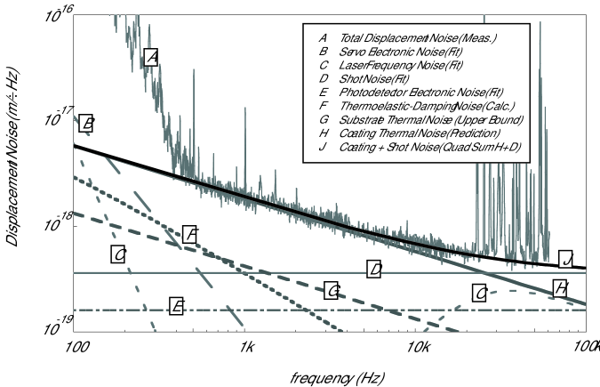
Figure 3 shows the total displacement noise of the interferometer, with common-mode rejection implemented, along with contributions from various noise sources. The theory curve (J) is the sum, in quadrature, of the coating thermal noise in all four mirrors in the arm cavities and the measured constant shot noise. The theoretical model we use takes into account the different Young’s modulus and Poisson’s ratio of the coating and substrate, and it admits the possibility that the coating mechanical loss angle might be different for strains parallel and perpendicular to the substrate-coating interface. For a coating with thickness , Young’s modulus , and Poisson’s ratio , the thermal noise is [9]
| (1) | |||||
where and are the coating’s mechanical loss angles for strains parallel and perpendicular to the substrate-coating interface, respectively. ( and are the Young’s modulus and Poisson’s ratio for the substrate.)
If we assume the previously-reported value for of [18], we find that the perpendicular loss angle is the same as the parallel loss angle for coatings. It would be premature, however, to conclude that the loss is definitely isotropic, because of the large error bars imposed on by the uncertainty in and by the relatively weak dependence of on .
Note that, if we assume that the coating Young’s modulus and Poisson’s ratio are the same as those of the substrate, and that the mechanical loss of the coating is the same for strains parallel and perpendicular to the substrate-coating interface, the coating thermal noise formula takes on a particularly simple form [9],
| (2) |
Using the value for the loss angle obtained from the ringdown technique [18], we have an unambiguous prediction of the coating thermal noise that we can compare with our direct measurement. This prediction yields a theoretical curve that is within a few percent of the fit we performed using Equation 1 and thus agrees well with our observed noise floor.
The parameters used in our analysis were
| Substrate Young’s Modulus: | [9] | |
|---|---|---|
| Coating Young’s Modulus: | [9] | |
| Substrate Poisson’s Ratio: | [19] | |
| Coating Poisson’s Ratio: | [20] | |
| Coating thickness: | [15] | |
| Laser spot radius: | ||
| Parallel loss angle: | [18] | |
| Perpendicular loss angle: | (fit) |
The uncertainty in due to the fit is approximately ten percent. However, since the noise curve is roughly three times more sensitive to than it is to , the modest uncertainty in results in a fairly large uncertainty in .
The parallel loss angle reported in Reference [18] is for coatings made by a different manufacturer from the ones on our mirrors, but one of the conclusions of that paper was that most of the mechanical loss in a coating is intrinsic to the tantala layers. Our coatings nominally have the same chemical content and physical structure as those reported in Reference [18], so we assume that their results apply to our coatings.
It has been suspected for some time that the initial estimates of LIGO’s thermal noise floor [7] were high, because a viscous-damping model was assumed for the loss mechanism, as opposed to the structural-damping model elaborated after the initial design studies [13, 8, 21]. Because the expected event rate scales so strongly with the sensitivity level in a gravitational wave detector, even a small reduction in the fundamental noise floor can translate into a large increase in the event rate. If, as our results indicate, the noise floor of LIGO is dominated by structural-damping-mediated coating thermal noise with a coating loss of , the effective range for binary neutron star inspiral detection of this first-generation instrument could be as much as , almost twice the original estimate of [22]. For an isotropic distribution of sources, this would mean an almost eightfold increase in the rate of observed events.
Greater are the implications for advanced detector development. Currently there is a substantial effort to develop a coating that will exhibit lower levels of mechanical noise than the coatings used in the existing LIGO mirrors. The agreement, both qualitative and quantitative, between the indirect, ringdown measurements of coating loss and our direct observation of coating thermal noise gives us confidence in our understanding of this noise source in a real, high-sensitivity interferometer, allowing the prediction, and even design, of the noise floor of an advanced detector.
3 Acknowledgments
We acknowledge useful discussions with Stan Whitcomb and Gregg Harry, and electronics assistance from Rich Abbott and Flavio Nocera. This work was supported by the NSF under grant number PHY01-07417.
References
- [1] B. C. Barish, R. Weiss, LIGO and the detection of gravitational waves, Physics Today 52 (10) (1999) 44–50.
- [2] H. Lück, the GEO600 team, The GEO600 project, Classical and Quantum Gravity 14 (1997) 1471–1476.
- [3] B. Caron, A. Dominjo, C. Drezen, R. Flaminio, X. Grave, M. more, The Virgo interferometer, Classical and Quantum Gravity 14 (1997) 1461–1469.
- [4] K. Kawabe, the TAMA collaboration, Status of the TAMA project, Classical and Quantum Gravity 14 (1997) 1477–1480.
- [5] D. G. Blair, The first stage of the Laser Interferometer Gravitational Wave Observatory in Australia, General Relativity and Gravitation 32 (3) (2000) 371–383.
- [6] E. S. Phinney, The rate of neutron-star binary mergers in the universe - minimal predictions for gravity-wave detectors, Astrophys. J. 380 (1) (1991) L17–L21.
- [7] A. Abromovici, W. E. Althouse, R. W. P. Drever, Y. Gürsel, S. Kawamura, F. J. Raab, D. Shoemaker, L. Sievers, R. E. Spero, K. S. Thorne, R. E. Vogt, R. Weiss, S. E. Whitcomb, M. E. Zucker, LIGO: The Laser Interferometer Gravitational-Wave Observatory, Science 256 (1992) 325–333.
- [8] Y. Levin, Internal thermal noise in the ligo test masses: A direct approach, Phys. Rev. D 57 (1998) 659–663.
- [9] G. M. Harry, A. M. Gretarsson, P. R. Saulson, S. E. Kittelberger, S. D. Penn, W. J. Startin, S. Rowan, M. M. Fejer, D. R. M. Crooks, G. Cagnoli, J. Hough, N. Nakagawa, Thermal noise in interferometric gravitational wave detectors due to dielectric optical coatings, Class. Quantum Grav. 19 (2002) 897–917.
- [10] D. R. M. Crooks, P. Sneddon, G. Cagnoli, J. Hough, S. Rowan, M. M. Fejer, E. Gustafson, R. Route, N. Nakagawa, D. Coyne, G. M. Harry, A. M. Gretarsson, Excess mechanical loss associated with dielectric mirror coatings on test masses in interferometric gravitational wave detectors, Class. Quantum Grav. 19 (5) (2002) 883–896.
- [11] H. B. Callen, T. A. Welton, Irreversibility and generalized noise, Phys. Rev. 83 (1951) 34–40.
- [12] H. B. Callen, R. F. Greene, On a theorem of irreversible thermodynamics, Phys. Rev. 86 (1952) 702–710.
- [13] P. R. Saulson, Thermal noise in mechanical experiments, Phys. Rev. D 42 (1990) 2437–2445.
- [14] Z. L. Wu, P. K. Kuo, L. Wei, S. L. Gu, R. L. Thomas, Photothermal characterization of optical thin films, Thin Solid Films 236 (1993) 191–198.
- [15] Research electro-optics, http://www.reoinc.com.
- [16] R. W. P. Drever, J. L. Hall, F. V. Kowalski, J. Hough, G. M. Ford, A. J. Munley, H. Ward, Laser phase and frequency stabilization using an optical resonator, Applied Physics B 31 (1983) 97–105.
- [17] E. D. Black, An introduction to Pound-Drever-Hall laser frequency stabilization, American Journal of Physics 69 (1) (2001) 79–87.
- [18] S. D. Penn, P. H. Sneddon, H. Armandula, J. C. Betzweiser, G. Cagnoli, J. Camp, D. R. M. Crooks, M. M. Fejer, G. A. M., G. M. Harry, J. Hough, S. E. Kittelberger, M. J. Mortonson, R. Route, S. Rowan, C. C. Vassiliou, Mechanical loss in tantala/silica dielectric mirror coatings, Class. Quantum Grav. 20 (13) (2003) 2917–2928.
- [19] V. B. Braginsky, M. L. Gorodetsky, S. P. Vyatchanin, Thermodynamical fluctuations and photo-thermal shot noise in gravitational wave antennae, Phys. Lett. A 264 (1999) 1–10.
- [20] G. Harry, Encorporating coating anisotropy into coating thermal noise, Tech. Rep. T040029-00-R, LIGO (2004).
- [21] K. Numata, Wide-band direct measurement of thermal fluctuations in an interferometer, Phys. Rev. Lett. 91 (26) (31 Dec. 2003) 260602.
- [22] R. Adhikari, private communication.