Abstract
In this paper, it is shown, using a geometrical approach, the isotropy of the velocity of light measured in a rotating frame in the Minkowski space-time, and it is verified that this result is compatible with the Sagnac effect. Furthermore, we find that this problem can be reduced to the solution of geodesic triangles in a Minkowskian cylinder. A relationship between the problems established on the cylinder and on the Minkowskian plane is obtained through a local isometry.
keywords:
isotropy, velocity of light, Sagnac effect[Isotropy of the velocity of light and the Sagnac effect]Isotropy of the velocity of light and the Sagnac effect
Isotropy of the velocity of light
1 Introduction
One of the most celebrated results of the Theory of Relativity is the one known as the Sagnac effect [1], which appears when two photons describe, in opposite directions, a closed path on a rotating disk returning to the starting point. Physically, the Sagnac effect is essentially a phase shift between two coherent beams of light travelling along paths in opposite senses in an interferometer placed on a rigidly rotating platform [2]. This phase shift can be explained as a consequence of a time delay, so the Sagnac effect can also be measured with atomic clocks timing light rays sent, e.g., around the rotating Earth via the satellites of the Global Positioning System [3]. From a geometrical approach, such phase shift has also been related [4] to the fact that the time component of the anholonomity object, corresponding to the choice of an orthonormal frame on the space-time, is different from zero.
The Sagnac effect outlines the problem of the isotropy of the velocity of light with respect to a non-inertial observer fixed on the rotating disk. This problem has been treated from different points of view. In [5], it is pointed out that the Sagnac time delay, measured by one single clock, is due to an anisotropy in the global speed of light for the non-inertial observer, in contradiction with the local Einstein synchronization convention. Another approach is found in [6]. There, the speed of light in opposite directions is the same, both locally and globally. The proof is performed using three clocks located at the initial and final positions of the two photons, and by extrapolating point to point, the local Einstein synchronization procedure to the whole periphery of the disk. The disagreements between both approaches are connected with the problem of the global time synchronization of points on the periphery of a rotating disk. Only if this global synchronization were possible there would exist a well defined spatial length between different points on the boundary of the rotating disk.
In this paper we consider an ideal rotating disk with negligible gravitational effects, thus the effects due to gravitational fields —that require the application of general relativistic techniques as those in [7] or [8], where exact and post-Minkowskian solutions are used— are not considered here. We will also show the isotropy of the velocity of light measured in a rotating frame in the Minkowski space-time. We verify that this isotropy is compatible with the Sagnac effect. For this we take into account that every kinematical problem in special relativity can always be translated into a geometrical problem on space-time.
Note on this respect that some authors have need to introduce some dynamical explanations for explaining the rotating disk problem [9].
An outline of the paper is as follows. In Sec. 2 we give a brief account of the technique used by Rizzi and Tartaglia [6] and describe how the use of the hypothesis of locality, (see [10]) offers an explanation of the Sagnac effect in the framework of special relativity, without using the anisotropy of a global speed of light. In Sec. 3, we solve this problem in terms of the world-function associated to the geodesic determined by the world-lines of the observer and the photon and the simultaneity space corresponding to the observer. In Sec. 4 a formulation of the problem using the solution of geodesic triangles is obtained. Finally, in Sec. 5 a relationship between the problem stated on a Minkowskian cylinder and on a Minkowskian plane is obtained.
2 The rotating disk and the Sagnac effect
Let be a disk of radius , and let us denote by the circle bounding . We consider an inertial reference frame , where is the center of and is an orthonormal basis for the Euclidean space . In the coordinate system associated to , the points in have coordinate equal to zero. It will also be useful to consider polar coordinates on . Now we assume that the disk is uniformly rotating about the axis, with angular velocity . In the space-time of Special Relativity in Minkowski coordinates, with , the motion of the points with polar coordinates , is given by world-lines , that in coordinates can be expressed as
| (1) |
This congruence of time-like curves determines a cylinder . On the cylinder both a metric is induced by the metric , which in comoving coordinates , reads
| (2) |
where
| (3) |
and a Killing vector field given by a combination of a rotation and a time translation, that, at each point , is , are defined. The associated Killing congruence has non null vorticity within the cylinder but is zero outside it. So, the vorticity and the 4-velocity play an analogous role to the magnetic field and the 4-electromagnetic potential, respectively, of the Aharonov-Bohm effect in electrodynamics, [11]. The metric (2) is globally stationary and locally static; therefore a local splitting of can be obtained using local hypersurfaces locally orthogonal to the trajectory of the rotating observer, as in [12]. Even a global operational quotient space by the Killing congruence can be build, by using the radar distance as a spatial distance [13].
In general, for every two points , joined by a geodesic , being a special parameter with , there is a function —the world function in Synge’s terminology, [14]— defined by
| (4) |
where denotes the tangent vector to the geodesic . Let us now consider, at the time , a point and the world-line corresponding to a curve in the congruence (1), with . On one may build a field of non-inertial reference frames . The proper time interval between two events with coordinate times and measured by the observer is given in terms of the world-function (4) as
| (5) |
Suppose that the rotating observer fixed on the circle carries a device which emits, at the time , two photons in opposite directions along the periphery of the disk. The world-lines of both photons are null helices. Their equations in the inertial reference frame read
| (6) |
where denotes the angular speeds of the photons given by , being the plus (resp. minus) sign associated to the photon moving in the same (resp. opposite) sense as the rotating disk.
At the initial time it is assumed that . The world-line corresponding to each photon cuts the curve at times , for which it is satisfied the condition . Therefore one obtains
| (7) |
The relationship between proper time on and the inertial coordinate time given in (5) establishes that the proper time in runs slow with respect to an inertial one. Hence, using (7) one obtains
| (8) |
The proper time increment measured by the observer among the arrival times of the two photons and is (see, e.g. [11]):
| (9) |
that, in the limit of small rotational speeds, takes the classical form given in [1]:
| (10) |
where is the disk area.
The Sagnac time delay is the desynchronization of a pair of clocks after a complete round trip, which has been initially synchronized and sent by the rotating observer to travel in opposite directions, [6]. In this case, the time differences along a complete round trip on the periphery of the disk, are not uniquely defined and the measurement of each one must be corrected by half the Sagnac time delay when compared with an identical clock remaining fixed at the initial position. After this correction is made, the global light speed is the same for the photon moving on in opposite sense. This is in fact what is done in the Global Positioning System, [3]. Note, on the other hand, that if the readings of both clocks are not corrected by half the Sagnac time (9), one obtains an anisotropic velocity of light, as in [5].
3 Measurement of relative speeds in Minkowski space-time
Let us assume that at the time , in the inertial reference frame , a non-inertial observer at a fixed point emits a pulse of light in the same direction of the movement of the disk. The event corresponds in the cylinder to the point with cylindrical coordinates . We now determine the relative speed of the ray of light with respect to the non-inertial frame .
The world-lines for the observer and the photon can be expressed in cylindrical coordinates, in the form
| (11) |
respectively. The curve is the time-like helix corresponding to a non-inertial observer fixed at the point on the disk. The curve describes the null helix of the photon co-rotating with the disk.
On the world-line one can determine a vector field such that the orthogonality condition, , is satisfied. For each point on , one builds a space-like geodesic on the cylinder , corresponding to the initial data
| (12) |
The geodesic can be interpreted as the locus of locally simultaneous events on an arc of the circle as seen by the rotating observer. For the construction of the simultaneity space , the hypothesis of locality given in [10] is used, which establishes the local equivalence of an accelerated frame and a local inertial frame with the same local speed. In this way, a slicing of the cylinder through a family of sections orthogonal to the congruence of curves is obtained.
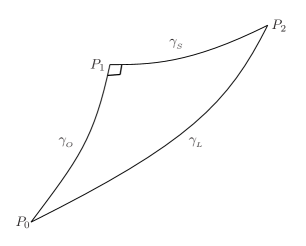
When the rotating frame reaches the point in the curve , the world-function is the square of the proper time (up to a constant factor) between the events and of space-time, measured by the non-inertial observer. At the time the photon lies on the point of the local simultaneity space relative to the non-inertial rotating observer. Since both the non-inertial observer and the photon move on , the corresponding points in space-time remain on the Minkowskian cylinder . Consider the point given by the intersection of the curves and , (see Fig. 1):
| (13) |
4 Equivalent formulation of the problem
Result (15) can be compared with that obtained by using the solution of geodesic triangles on the semi-Riemannian manifold For this we consider a geodesic triangle on a 2-manifold as shown in Fig. 2. For arbitrary points and , let denote the covariant derivative of (4) with respect to the coordinates of , and denote by the vector associated to by means of the metric .
Let us assume that the Riemannian curvature of a surface is small and we will use the same notation as in [14], Chapter II. If is an orthonormal basis on , one can build a field of reference frames on by parallel transport of this frame along all geodesics through . On the field , the vector field , tangent to one of these geodesics on an arbitrary point, has constant components . On the other hand, the components of the symmetrized Riemann tensor
| (16) |
will be denoted by .
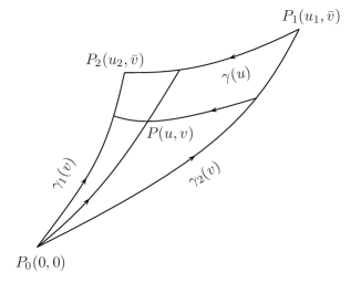
For the geodesic triangle determined by the curves , and (with , see Fig. 2) a relationship between the world-functions of the sides of this triangle is obtained in [14]:
| (17) |
where
| (18) |
and denotes the covariant derivative of fourth order of the world-function for an arbitrary . An explicit approximate expression for appears in [14] p. 73, written in terms of the Riemann tensor and its covariant derivatives. An application of this solution to build Fermi coordinates in general space-times of small curvature is given in [15]. In general it is satisfied that
| (19) |
where is the polynomial
| (20) |
and symbol , defined as
| (21) |
is constant on , so that vanishes. In (21) are the components of at points respectively. In the problem considered in this work, the metric (2) is uniform on the cylinder , and the Riemannian curvature is zero, therefore expression (18) vanish.
Therefore, one obtains for the solution of the same triangle in the point
| (22) |
where the covariant derivatives are calculated now at the point . Now, since the geodesic is null and the geodesics and are orthogonal in ; then, from (22) one obtains
| (23) |
Consequently, the ratio
| (24) |
coincides with (15).
5 Reduction to the Minkowskian plane
In this section, we will see that the rotating observer on the disk has a specific characteristic which other different non-inertial observers do not have in general. In the first place, it is observed that expression (5), which relates the proper time of a non-inertial observer fixed on the rotating disk (moving with constant angular speed , such that ) to the coordinate time , coincides with the expression relating the inertial observer’s time to the time of another inertial reference frame boosted with rectilinear speed . Then one concludes that only by measuring proper time, a rotating observer will not be able to determine the local inertial or non-inertial character of the frame rotating uniformly on the disk. The only magnitude that he will be able to measure in that case is the speed modulus .
Now, let us consider a boosted rectilinear inertial frame . To measure the speed of a photon moving in the same direction as with respect to this frame we consider the configuration shown in Fig. 3.
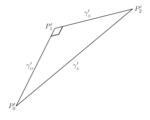
Here represents the straight line described by the observer (we are assuming that the speed is ) in a Minkowskian plane . On the other hand, the null straight line represents the trajectory that one photon describes, and, finally, the line is the space-like straight line of simultaneous events to the emission event of the photon. This line is everywhere –orthogonal to the observer line at the event . Explicitly, taking , these curves are given by
| (25) |
where now . This can be verified directly from Figure 2.
Moreover, point at which cuts to has the coordinates
| (26) |
Therefore, keeping in mind again that , one obtains that the distances between and along and between and along are
| (27) |
where denotes the world-function associated to points and the metric . The relative speed between the light ray and the boosted rectilinear inertial observer, defined through the ratio
| (28) |
coincides with .
The identity between these expressions and those obtained before in Sec. 3 is clear. Indeed, if is substituted for those expressions are coincident. The fact that the values of and coincide with the values and obtained in the problem solved on the cylinder is due to a local isometry between the Minkowskian plane , which contains the line of universe of the boosted rectilinear inertial observer, and the Minkowskian cylinder , which contains the world-line of the non-inertial rotating frame.
As pointed out at the beginning of this section, the non-inertial rotating observer on the disk has a specific characteristic which other different non-inertial observers do not have, in general. In this case, the expression (5), relating the proper time and the coordinate time , is the same as in inertial frames. This allows to build an isometry between cylinder and the plane as follows.
Let be a smooth map between a neighborhood of , which contains the geodesic triangle considered above, and the plane . Denote by and the tangent spaces to and at the points respectively. The map is such that its differential, , is a linear isometry for every point :
| (29) |
for every . Let us consider a map such that . We determine a function satisfying condition (29). This function is determined through the partial differential system
| (30) |
whose solution is the function . Therefore an isometry as
| (31) |
maps into , retaining the same coordinate time in both manifolds.
The geodesic triangle of vertices in is mapped into the straight triangle in . Therefore, it is possible to translate the problem of measuring the speed of light with respect to a non-inertial reference frame, which describes a circumference rotating uniformly, to the problem of measuring the speed of light by an inertial reference frame, being the velocity equal to in both cases. By means of this local isometry, for the point on the cylinder there exists a corresponding in the plane, which has the same coordinates as the event , obtained in Sec. 3 by means of the hypothesis of locality with the slicing of .
Returning to the initial problem of two photons describing the periphery of a rotating disk in opposite senses, it is observed that one obtains the same result for both photons, as it may be verified solving the corresponding problem on the Minkowskian plane, where the speed of light is independent of the direction followed by the photons.
6 Concluding remarks
In [6], using the locus of locally simultaneous events to the non-inertial rotating observer (given by space-like helices in a Minkowski space-time), it is shown that the speed of light measured by a non-inertial observer fixed on the disk rim always turns out to be both locally and globally. The local isometry (31), shows how this coincidence is obtained. In fact, this local isometry allows to calculate relative speeds (24) and (28) in the problem of the rotating disk, mapping the problem from the multiply connected Minkowskian cylinder to another one established in the simply connected Minkowskian plane.
From the above reasoning, one observes that although the observer is non-inertial this is not reflected on the measurements of relative speeds. This is because the module of the centripetal acceleration of the observer , coincides with the module of the normal curvature of the world-line of the observer on the cylinder . A rotating observer corresponds to a Killing trajectory, so its world-line is a geodesic on this cylinder. Moreover, the Gaussian curvature of the cylinder is zero. So, the non-inertiality of the rotating observer is not reflected in the measurement procedure, because this is only based on the first fundamental form of .
Finally, we remark that the frame of reference considered in the problem of a rotating disk is very special, so the problem can be established on a circular cylinder. A more general case would be, for example, that of a deformable closed loop filament moving and preserving a non-circular shape.
Acknowledgements.
The authors wish to thank A. Tartaglia for a discussion on the subject of this work. This work was completed with the support of the Junta de Castilla y León (Spain), project VA014/02.99
References
- [1] G. Sagnac, C.R. Acad. Sci. Paris, 157, 708 (1913).
- [2] E.J. Post, Rev. Mod. Phys., 39, 475, (1967); G.E. Stedman, Rep. Prog. Phys., 60, 615 (1997).
- [3] D. Allan, N. Ashby and M. Weiss, Science, 228, 69 (1985).
- [4] J.F. Corum, J. Math. Phys., 18, 770 (1977); J.-F. Pascual-Sánchez, Summaries of workshop D.1 at 14th International Conference on General Relativity and Gravitation, Florence, 1995, (unpublished).
- [5] F. Selleri, Found. Phys. Lett., 10, 73 (1997); A. Peres, Phys. Rev. D, 18, 2173 (1978).
- [6] G. Rizzi and A. Tartaglia, Found. Phys., 28, 1663 (1998).
- [7] A. Ashtekar, J. Math. Phys., 16, 341 (1975); A. Tartaglia, Phys. Rev. D, 58, 064009 (1998).
- [8] S. Kopeikin and G. Schäfer, Phys. Rev. D, 60, 124002 (1999).
- [9] G. Cavalleri, Nuovo Cimento, 53 B, 415 (1968); Ø. Grøn, Am. J. Phys., 43, 869 (1975), Found. Phys., 10, 499 (1980); T. E. Phipps, Found. Phys., 10, 289 (1980), 10, 811 (1980); D. Dieks, Eur. J. Phys., 12 , 253 (1991); T.A. Weber, Am. J. Phys., 65, 946 (1997).
- [10] B. Mashhoon, Phys. Lett. A, 145, 147 (1990); A. Tartaglia, in Reference Frames and Gravitomagnetism, eds. J.-F. Pascual-Sánchez, L. Floría, A. San Miguel, F. Vicente, (World Scientific, Singapore, 2001).
- [11] J. Anandan, Phys. Rev. D 24, 338 (1981).
- [12] L. Landau and E. Lifshitz, The Classical Theory of Fields, (Pergamon Press, Oxford, 1971).
- [13] Ll. Bel, J. Martín, A. Molina, J. Phys. Soc. Japan, 63, 4350 (1994); G. Rizzi, M. L. Ruggiero, Found. Phys., 32, 1525 (2002).
- [14] J.L. Synge, Relativity: The General Theory, (North–Holland, Amsterdan, 1960).
- [15] J.M. Gambi, P. Romero, A. San Miguel and F. Vicente, Int. J. Theor. Phys., 30, 1097 (1991).