Squeezed-input, optical-spring, signal-recycled gravitational-wave detectors
Abstract
We theoretically analyze the quantum noise of signal-recycled laser interferometric gravitational-wave detectors with additional input and output optics, namely frequency-dependent squeezing of the vacuum state of light entering the dark port and frequency-dependent homodyne detection. We combine the work of Buonanno and Chen on the quantum noise of signal-recycled interferometers with ordinary input and output optics, and the work of Kimble el al. on frequency-dependent input and output optics with conventional interferometers. Analytical formulas for the optimal input and output frequency dependencies are obtained. It is shown that injecting squeezed light with the optimal frequency-dependent squeezing angle into the dark port yields an improvement on the noise spectral density by a factor of (in power) over the entire squeezing bandwidth, where is the squeezing parameter. It is further shown that frequency-dependent (variational) homodyne read-out leads to an additional increase in sensitivity which is significant in the wings of the doubly resonant structure. The optimal variational input squeezing in case of an ordinary output homodyne detection is shown to be realizable by applying two optical filters on a frequency-independent squeezed vacuum. Throughout this paper, we take as example the signal-recycled topology currently being completed at the GEO 600 site. However, theoretical results obtained here are also applicable to the proposed topology of Advanced LIGO.
I introduction
Gravitational waves (GW) have long been predicted by Albert Einstein using the theory of general relativity, but so far have not been directly observed Thorne87 . Currently, an international array of first-generation, kilometer-scale laser interferometric gravitational-wave detectors, consisting of GEO 600 geo02 , LIGO LIGO , TAMA 300 TAMA and VIRGO VIRGO , targeted at gravitational-waves in the acoustic band from 10 Hz to 10 kHz, is going into operation. These first-generation detectors are all Michelson interferometers with suspended mirrors. Injecting a strong carrier light from the bright port, the anti-symmetric mode of arm-lengths oscillations (e.g. excited by a gravitational wave) yields a sideband modulation field in the anti-symmetric (optical) mode which is detected at the dark output port. To yield a high sensitivity to gravitational waves, long arm lengths of 300 m up to 4 km and circulating laser power in the order of 10 kW are going to be realized in 2003 with the help of the technique of power recycling DHKHFMW83pr .
GEO 600 is the only first-generation detector that not only uses power recycling, but also includes the more advanced technique of signal recycling Mee88 . The idea of signal recycling is to retro-reflect part of the signal light at the dark port back into the interferometer, establishing an additional cavity which can be set to resonate at a desired gravitational-wave frequency. Signal recycling leads to a well known (optical) resonance structure in the interferometer’s sensitivity curve. This resonance can already beat the standard quantum limit (SQL) BCh01a ; BCh01b , which is the upper bound for the sensitivity of conventional interferometers without signal recycling and with conventional input and output optics. A further benefit of signal recycling is the reduced optical loss due to imperfect mode matching from the mode healing effect SMe91 . The next-generation detectors currently being planned are likely to use this technique, for example the Advanced LIGO (LIGO II) GSSW99 .
Buonanno and Chen also predict a second, opto-mechanical resonance in signal-recycled interferometers, around which the interferometer gains sensitivity, and can also beat the standard quantum limit BCh01a ; BCh01b ; BCh02a ; BCh03a . Their work has been limited to signal-recycled interferometers with arm cavities, or interferometers with one single end mirror in each arm, and with infinitely heavy beamsplitters. In all cases considered, coherent vacuum was entering the interferometer’s dark port, i.e. no additional input and output optics were investigated. On the other hand, Kimble et al. investigated these additional input and output optics for the conventional LIGO detector topology without signal-recycling KLMTV01 building on earlier work on squeezed-input interferometers Cav81 ; Unruh82 ; GLe87 ; JRe90 ; PCW93 and variational-output interferometers VMa93 ; VZu95 ; VMa96a ; VMa96b ; VZu98 .
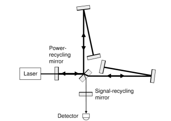
In this paper, we investigate the benefit of squeezed light with frequency-dependent squeezing angle injected into the interferometer’s dark port and also the benefit of frequency-dependent (variational) homodyne readout, using the two-photon input-output formalism of quantum optics CSc85 . In sections III and IV of this paper we derive analytical expressions for the optimized frequency dependencies of squeezing angle and homodyning angle for optical-spring signal-recycled interferometers, respectively. For definiteness, our results are presented using the Michelson topology of GEO 600. Unlike the LIGO, VIRGO and TAMA 300 interferometers, GEO 600 has folded arms and no arm cavities (Fig. 1). We plot and compare the spectral densities of the quantum noise of the GEO 600 topology without and with additional input and output optics. Using the coupling parameter of Advanced LIGO, the results are readily applicable to the proposed LIGO topology.
II Signal recycling
By placing a mirror in the dark port of an interferometer a cavity between this so-called signal-recycling mirror and the two end mirrors of the interferometer is formed. The length of this cavity can be tuned independently and can be made resonant at some signal frequency . Thus the signal is recycled and amplified due to an increased interaction time. The original idea of the signal-recycling (SR) topology, i.e. a mirror in the dark port, was due to Meers Mee88 , who proposed its use for dual-recycling, which is the combination of power- and signal-recycling. Later, Mizuno et al. MSNCSRWD93 ; Mizuno95 and Heinzel et al. Heinzel99 ; HMSRWD96 proposed the scheme of resonant sideband extraction, which uses a detuned signal-recycling mirror to extract the signal from high-finesse arm cavities. Both schemes of tuned and detuned signal-recycling cavities have been experimentally demonstrated by Heinzel et al. HSMSWWSRD98 and Freise et al. FHSMSLWSRWD00 with the 30 m laser interferometer in Garching near Munich. Recently the GEO 600 interferometer in Ruthe near Hannover has been completed by the implementation of the signal-recycling mirror. Since GEO 600 has no Fabry-Pérot cavities (Fig. 1) the SR-mirror will be operated at or close to resonance. Relevant technical parameters of GEO 600 are summerized in Table 1.
| symbol | physical meaning | numerical value |
|---|---|---|
| mirror mass (each) | ||
| effective arm length | ||
| circulating light power | ||
| angular frequency of carrier light | ||
| power reflectivity of SRM | ||
| SR-cavity detuning |
Whereas it was well known that signal-recycled interferometers exhibit an optical resonance, Buonanno and Chen BCh01a ; BCh01b have recently shown that SR-interferometers exhibit a second resonance, which is opto-mechanical. This resonance stems from the classical opto-mechanical coupling of the light field with the anti-symmetric mode of the otherwise free mirrors BCh02a : in detuned signal-recycling schemes, the phase-modulation sidebands induced by a gravitational wave are partly converted into amplitude modulations, which beat with the carrier field, producing a motion-dependent force and acting back on the test masses. This classical back-action force can be thought of as generated by an optical spring. The optical spring makes the test masses no longer free, and can shift their resonant frequencies upwards into the detection band. The interferometer gains sensitivity on and around this resonance, and can beat the standard quantum limit BCh01a ; BCh01b ; BCh02a . Whereas the optical resonance is primarily determined by the detuning of the SR-cavity with respect to the carrier-frequency (Fig. 5.8 in HarmsDipl ), the opto-mechanical resonance appears at a specific sideband frequency of the carrier light which depends on the interferometer’s topology, the mirror masses , the light-power inside the interferometer and the detuning of the SR cavity from its resonance. The opto-mechanical coupling of the light field with the anti-symmetric mode of the interferometer also leads to the phenomenon of ponderomotive squeezing BMa67 , i.e. the amplitude and phase quantum noise become correlated. This quantum effect is automatically considered by the formalism revealing the optical-spring behaviour. However, as pointed out in BCh01b , in SR interferometers the ponderomotive squeezing only seems to be a secondary factor that enables the interferometer to beat the SQL, whereas the classical resonant amplification of the signal provides the main factor.
The investigations led by Buonanno and Chen focused on the topology of the proposed Advanced LIGO configuration, which consists of a dual-recycled Michelson-interferometer with a Fabry-Pérot cavity in each arm. Due to the weak laser power at the beamsplitter, the opto-mechanical coupling of the light with the beamsplitters free oscillation was neglected. In contrast, GEO 600 is a dual-recycled interferometer that builds up a high intensity field by means of a power-recycling (PR) mirror in the bright port of the interferometer. Therefore, the motion of the beamsplitter (BS) in GEO 600 is affected by power fluctuations of fields impinging from different directions. Nevertheless, assuming that the laser is shot-noise limited, the opto-mechanical coupling at the beamsplitter exerts only minor changes on the noise spectrum of the output. It can intuitively be understood that the quantum back-action noises associated with the arm mirrors, which have a reduced mass of the actual mirror mass due to folding the arms, clearly dominates the beamsplitter of . Throughout this paper we do not consider the effect of radiation-pressure noise on the beamsplitter. This has also been studied but will be presented in detail elsewhere Harms03b . Henceforth the term “ideal GEO 600” refers to the interferometer with opto-mechanical coupling of the beamsplitter neglected.
The optical noise in an interferometer can be expressed in terms of the (single-sided) noise spectral density of the output field normalized by the transfer function of the signal. The noise spectral density is obtained from the input-output relation, which maps the numerous input fields and the gravitational-wave signal onto the detected output field . Here we note that no additional noise due to the quantization of the test masses has to be considered. The sole forms of quantum noise affecting the output noise in interferometric gravitational wave detectors are the shot noise and the radiation pressure noise BGKMTV02 .
The following calculations are most easily accomplished in the Caves-Schumaker two-photon formalism CSc85 , where the optical fields are decomposed into amplitude and phase quadratures, which can then be put together into a vector, e.g., for the output field of the interferometer
| (1) |
where are the output amplitude and phase quadratures. The input-output relation for a lossless SR interferometer can be cast into the following form:
| (2) |
Here, designates a -matrix. Its four components are HarmsDipl :
| (3) |
and is given by
| (4) |
Thus, contains an overall phase factor . and denote the amplitude reflectivity and transmissivity of the SR mirror. The signal transfer functions for the two quadratures are given by:
| (5) |
Remarkably, the input-output relations are formally identical for both configurations, Advanced LIGO and ideal GEO600. Their distinguishing properties lie in the definition of the opto-mechanical coupling-constant , the standard quantum-limit and the phase-angle which are also functions of the modulation-frequency .
| symbol | GEO 600 | Advanced LIGO |
|---|---|---|
A phase-sensitive measurement (i.e. homodyne or heterodyne) yields a photocurrent which depends linearly on a certain combination of the two output quadrature-fields:
| (6) |
where is the homodyne angle (i.e. the angle of homodyne detection). The radiation-pressure forces acting on the mirrors are proportional to the amplitude quadrature and the motion-induced sideband fields are excitations of the light’s phase quadrature.

The noise spectral density when detecting the quadrature is determined by the transfer matrix and the signal transfer-functions . It assumes the form [see, e.g., Ref. BCh01a ],
| (7) |
provided that the input field entering from the dark port is a coherent vacuum field. Since is a complex vector, the product represents a symmetrized product
| (8) |
The same holds for the matrix product in the nominator. Its symmetrization becomes necessary, if a more general interferometer topology is considered with complex coupling constant . The expression in Eq. (7) for the noise spectral density is valid for any optical system whose transfer function can be given the form of Eq. (2).
Using Eq. (7) and the parameters and definitions in Table 1 and 2 we are now able to plot the linear noise spectral density of the ideal GEO 600 topology for output quadrature fields of arbitrary values of the angle . Fig. 2 shows the two spectral densities and compared with the SQL (straight solid line). It can be seen that for both quadrature angles the SQL is beaten at frequencies around . This noise minimum is due to the opto-mechanical resonance (i.e. the optical-spring effect). The second minimum at around corresponds to the optical resonance of the SR cavity. This resonance can also beat the SQL when higher reflectivities of the SR mirror are used. For further comparison, the quantum noise limit of a conventional GEO 600 without signal-recycling is also given (solid line in the upper part of Fig. 2). The dashed lines represent the two contributions to this (conventional) limit, the uncorrelated white shot noise and the radiation-pressure noise (). The limit given here is calculated for a circulating light power of that reaches the SQL at and of course can never beat the SQL. It is interesting to note that light powers of around are needed to shift the conventional limit downwards to get standard quantum noise limited sensitivity at around (not shown in Fig. 2).
In the next two sections we investigate how the sub-SQL spectral noise densities of signal-recycled gravitational wave detectors can be further improved by squeezed light injected into the dark port of the interferometer and by a frequency dependent read-out scheme.
III Signal recycling and squeezed light input
As first proposed by Caves Cav81 , squeezed light can be employed to reduce the high power requirements in GW interferometers. Later Unruh Unruh82 and others GLe87 ; JRe90 ; PCW93 ; KLMTV01 have found and proven in different ways that squeezed light with a frequency dependent orientation of the squeezing ellipse can reduce the quantum noise down to values beyond the standard quantum limit.This research was done on interferometer topologies without signal-recycling. Chickarmane et al. CDh96 ; CDRGBM98 investigated the squeezed-input signal-recycled interferometer at low laser powers, i.e. the shot-noise limited case. In this section we consider the squeezed-input signal-recycled interferometer at high laser powers including the effect of back-action noise.
As discussed in Sec. IVB of Ref. KLMTV01 , squeezed vacuum is related to the ordinary coherent vacuum state by an unitary operator
| (9) |
where is the squeezing parameter, and the squeezing angle (for an introduction to squeezed light see for example WallsMilburn ). Alternatively, we can transform the input state back to the vacuum state, by
| (10) |
and at the same time transform the input quadrature operators accordingly [Eq. (A8) of Ref. KLMTV01 ],
| (11) | |||||
where
| (12) |
From Eq. (11), we also see that a squeezed vacuum with squeezing angle can be obtained from a second-quadrature squeezing by applying a rotation of (note the minus sign). Any further rotation of quadratures will also add (with a minus sign) to the squeezing angle.
The input-output relation of the lossless interferometer with fixed beamsplitter becomes
| (13) |
implying a noise spectral density of
| (14) |
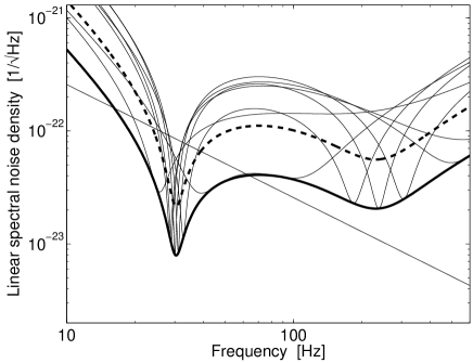
Note that here is a real matrix with an overall phase factor in front (cf. Eq. (3)). Fig. 3 shows an array consisting of 7 curves (thin lines) where the quadrature angle is constant and the frequency independent squeezing angle is varied. In all cases the squeezing parameter has been set to unity. Interestingly a variation of the frequency-independent squeezing angle causes a frequency shift of both resonances. For comparison, the standard quantum limit (straight line) and the spectral noise density in the quadrature at without squeezed input is also given (dashed line). As we can see, each individual frequency-independent value for can be advantageous to the case without squeezing only in a certain frequency band. Obviously, the envelope of the minima of the squeezed input array, as also drawn in the graph (lower bold line), is physically meaningful since it can in principle be realized by applying squeezed light with a squeezing angle optimized for each side-band frequency. Such light is called frequency-dependent squeezed light and yields a broad-band improvement in the quantum noise limited sensitivity. In the final paragraphs of this section we now derive an analytical expression for the optimized spectral noise density. Suppose now the squeezing angle can be an arbitrary function of frequency, and is always positive, then as we can tell from Eq. (14), the optimal should make
| (15) |
or
| (16) |
yielding an optimal noise spectrum of
| (17) |
This expression turns out to be identical to the noise spectral density without squeezing in Eq. (7) being suppressed by a factor of . This result can be understood intuitively as follows. The input quadrature field is going to be rotated (and possibly ponderomotively squeezed) by the matrix before being detected. The minimal noise quadrature of the squeezed state should therefore be rotated conversely before being injected into the interferometer, such that the detector always “sees” the minimal noise.
Squeezed vacuum can be generated with a variable but frequency-independent squeezing angle (see for example BISM98 ). A frequency-dependent squeezing angle can be obtained subsequently by filtering the initial squeezed light through detuned Fabry-Pérot (FP) cavities, as proposed by Kimble et al. KLMTV01 , which can rotate the quadratures in a frequency dependent way. For small frequencies (), a detuned FP cavity of length rotates the reflected quadrature in the following way:
| (18) |
with
| (19) |
and
| (20) |
where is defined by the resonant frequency and by which is the half-linewidth of the cavity: . As further shown by Purdue and Chen in Appendix A of Ref. PCh02 , several such Fabry-Pérot filter cavities can be combined to give a broad category of frequency dependent rotation angles. Adopting their formulas [cf. Eqs. (A.8)—(A.14)] into our context, we found that, in order to realize an additional squeezing angle with the form of
| (21) |
we first need to obtain an initial frequency independent squeezed state with
| (22) |
and then filter this squeezed light with filters whose complex resonant frequencies differ from by , , with being the roots of the characteristic equation:
| (23) |
[Note that are the roots with the appropriate sign of imaginary part, in our case negative.]
Suppose the readout quadrature is frequency independent, from the ideal input-output relation of GEO 600, we see that the desired from Eq. (16) is indeed of the form of Eq. (21) when is expanded to the leading order 111Note that, one has to take in order to get a meaningful expansion.. Two filter cavities are necessary for the generic case. However, as we look at the low-power limit, only one such filter is necessary. In this case, the input-output relation rotates the input quadratures into the output quadratures following the same law as a detuned cavity. Naturally, as we go through Eqs. (22) and (23), we find that the required initial additional squeezing angle is
| (24) |
which puts the minor axis of the noise ellipse onto the quadrature, while the required cavity has resonant frequency
| (25) |
which is just “opposite” to the signal-recycling resonant frequency,
| (26) |
and cancels the rotation induced by signal-recycling. For full-power GEO 600 interferometers, the initial additional squeezing angle is still given by Eq. (24), while the frequency-dependent part requires two cavities determined by the following characteristic equation:
| (27) |
It is straightforward to solve for the four roots (in two pairs) of the characteristic equations. The corresponding transmissivity of the input mirror and the detuning of the filter cavity can be derived from these roots by virtue of Eq. (25).
IV Signal recycling, squeezed light input and variational output
As shown by Kimble et al. KLMTV01 , the quantum noise spectral density of a conventional interferometer without signal-recycling can benefit simultaneously from both, frequency-dependent squeezed light input and frequency-dependent homodyne read-out. In this section we investigate the optical-spring signal-recycled interferometer with corresponding additional input and output optics. We start from the result of the previous section and vary the angle of homodyne detection.
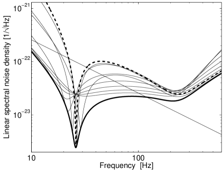
Fig. 4 shows an array of noise spectral densities of the output quadrature with varying detection angle which is here still frequency independent. The input vacuum at the dark port is optimally squeezed with squeezing parameter . Obviously, the array is bounded from below. This boundary corresponds to the optimized quantum noise spectral density of the signal-recycled interferometer. One member of the array is highlighted by a bold dashed line. Comparing the dashed curve with the optimized noise spectral density, one can see that the variational output provides a further improvement of the interferometer’s performance which is mainly an increased bandwidth of the sub-SQL sensitivity. At some frequencies the noise is reduced by a factor of 10. We emphasize that the optimized noise spectrum presented can not be further improved for this interferometer topology without increasing the squeezing parameter of the input vacuum. Obviously, our results are also significant without any squeezing of the input vacuum. The plots in Fig. 4 are not altered except for a shift upwards by a factor of .
In the final part of this section we give an analytical expression of the lower boundary starting from Eq. (17). has to be minimized with respect to the detection angle . One method to find the minimum noise is to determine analytically the minimum of the function . Then, a lengthy but straightforward calculation leads to a conditional equation for the optimized detection angle of the following form 222A similar analytic expression has also been obtained independently by Buonanno and Chen, but remained unpublished.:
| (28) |
Representing a general SR interferometer, the coefficients of the symmetric quadric are complex (and complex-valued) functions of the interferometers’ parameters () which determine the input-output relation Eq. (2). It is more convenient to express them in terms of the elements of the two symmetrized matrices , :
| (29) |
In general, Eq. (28) has two solutions corresponding to a local minimum and a local maximum of the noise density:
| (30) |
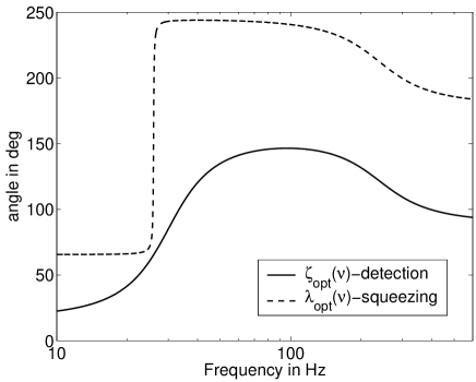
The minimum of the noise spectral density is given by inserting into Eq. (17). The optimized detection angle is shown in Fig. 5 together with the optimized squeezing angle of the input field which depends on according to Eq. (16). The form of both curves suggests that the filtering of the input and output light is accomplishable. Due to the frequency dependence of the squeezing and detection angle, one has to investigate first if an expansion in the form of Eq. (21) yields an expression which represents a manageable number of filter cavities. Furthermore, both spectra in Fig. 5 are sensitive to small changes of the parameters. Therefore, we do not propose a specific number of filter cavities needed to realize the frequency dependence.
V Conclusion
We have shown that the quantum-noise limited sensitivity of signal-recycled interferometers, like GEO 600 or LIGO II, can be improved by additional input and output optics. Although an optical-spring signal-recycled interferometer can already beat the standard quantum limit and ponderomotively generates squeezed light our results show that squeezed light input is compatible leading to a quantum noise reduction by the squeezing factor (in power). Variational output optics was proven to provide an additional benefit to the quantum noise limited sensitivity of signal-recycled interferometers. Our work augments the results by Buonanno and Chen BCh01a ; BCh01b ; BCh02a ; BCh03a and by Kimble et al. KLMTV01 and synthesizes their investigations.
We have provided fully optimized homodyning and squeezing angles, expressible in analytical formulas, although they are probably not easily achievable using the technique proposed by Kimble et al., which uses detuned FP cavities as optical filters.
However, in the special (sub-optimal) case with frequency-independent homodyning angle but frequency-dependent input squeezing angle, we found the optimal (frequency-dependent) input squeezing angle to be achievable by applying two subsequent filters on a frequency-independent squeezed light.
We did not analyze the effect of optical losses, but as pointed out by Kimble et al., the frequency-dependent input squeezing technique is less susceptible to optical losses than the variational readout and squeezed-variational schemes. A thorough study of optical losses will be published in a separate paper Harms03b .
We acknowledge A. Freise, H. Lück, G. Heinzel and B. Willke for many discussions providing us with valuable insight into signal-recycled interferometers. The research of YC is supported by the National Science Foundation grant PHY-0099568 and by the David and Barbara Groce fund at the San Diego Foundation. The author thanks the Albert-Einstein-Institut in Hannover for support during his visit. The author also thanks Alessandra Buonanno for collaboration in numerous earlier works, from which his contributions to this paper benefit.
References
- (1) K.S. Thorne, in 300 Years of Gravitation, edited by S.W. Hawking and W. Isreal (Cambridge University Press, Cambridge, England, 1987), pp. 330–458.
- (2) B. Willke et al., Class. Quantum Grav. 19, 1377 (2002).
- (3) A. Abramovici et al., Science 256, 325 (1992).
- (4) M. Ando et al., Phys. Rev. Lett. 86, 3950 (2001).
- (5) B. Caron et al., Class. Quantum Grav. 14 1461 (1997).
- (6) R. W. P. Drever et al. in Quantum Optics, Experimental Gravitationa, and Measurement Theory, edited by P. Meystre and M. O. Scully (Plenum, New York, 1983), p. 503–514.
- (7) B. J. Meers, Phys. Rev. D 38, 2317 (1988).
- (8) A. Buonanno and Y. Chen, Class. Quantum Grav. 18, L95 (2001).
- (9) A. Buonanno and Y. Chen, Phys. Rev. D 64, 042006 (2001).
- (10) K. A. Strain and B. J. Meers, Phys. Rev. Lett. 66, 1391 (1991).
- (11) E. Gustafson, D. Shoemaker, K. Strain and R. Weiss, LSC White paper on Detector Research and Development, LIGO Document Number T990080-00-D (Caltech/MIT, 11 September 1999). See also www.ligo.caltech.edu/ligo2/. Please note that this reference did not take into account the correct quantum-noise calculations that were later done by Buonanno and Chen.
- (12) A. Buonanno and Y. Chen, Phys. Rev. D 65, 042001 (2002).
- (13) A. Buonanno and Y. Chen, submitted (2002), arXiv:gr-qc/0208048,
- (14) H. J. Kimble, Y. Levin, A. B. Matsko, K. S. Thorne and S. P. Vyatchanin, Phys. Rev. D 65, 022002 (2001).
- (15) C. M. Caves, Phys. Rev. D 23, 1693 (1981).
- (16) W. G. Unruh, in Quantum Optics, Experimental Gravitationa, and Measurement Theory, edited by P. Meystre and M. O. Scully (Plenum, New York, 1982), p. 647.
- (17) J. Geabanacloche and G. Leuchs, J. Mod. Opt. , 34, 793 (1987).
- (18) M. T. Jaekel and S. Reynaud, Europhys. Lett. 13, 301 (1990).
- (19) A. F. Pace, M. J. Collett and D. F. Walls, Phys. Rev. A 47, 3173 (1993).
- (20) S. P. Vyatchanin and A. B. Matsko, JETP 77, 218 (1993).
- (21) S. P. Vyatchanin and A. B. Matsko, Phys. Lett. A 203, 269 (1995),
- (22) S. P. Vyatchanin and A. B. Matsko, JETP 82, 1007 (1996).
- (23) S. P. Vyatchanin and A. B. Matsko, JETP 83, 690 (1996).
- (24) S. P. Vyatchanin, Phys. Lett. A 239, 201 (1998).
- (25) C. M. Caves and B. L. Schumaker, Phys. Rev. A, 31, 3068 (1985); B. L. Schumaker and C. M. Caves, Phys. Rev. A 31, 3093 (1985).
- (26) J. Mizuno, K. A Strain, P. G. Nelson, J. M. Chen, R. Schilling, A. Rüdiger, W. Winkler und K. Danzmann, Phys. Lett. A 175, 273 (1993).
- (27) J. Mizuno, Comparison of optical configurations for laser-interferometric gravitational-wave detectors, Ph.D. thesis, Universität Hannover and Max-Planck-Institut für Quantenoptik, Garching, 1995, also available as MPQ report 203.
- (28) G. Heinzel, Advanced optical techniques for laser-interferometric gravitational-wave detectors, Ph.D. thesis, Universität Hannover and Max-Planck-Institut für Quantenoptik, Garching, 1999, also available as MPQ report 243.
- (29) G. Heinzel, J. Mizuno, R. Schilling, A. Rüdiger, W. Winkler und K. Danzmann, Phys. Lett. A 217, 305 (1996).
- (30) G. Heinzel, K. A Strain, J. Mizuno, K. D. Skeldon, B. Willke, W. Winkler, R. Schilling, A. Rüdiger, and K. Danzmann, Phys. Rev. Lett. 81, 5493 (1998).
- (31) A. Freise, G. Heinzel, K. A Strain, J. Mizuno, K. D. Skeldon, H. Lück, B. Willke, R. Schilling, A. Rüdiger, W. Winkler und K. Danzmann, Phys. Lett. A 277, 135 (2000).
- (32) J. Harms, Quantum Noise in the Laser-Interferometer Gravitational-Wave Detector GEO 600, Diploma thesis, Universität Hannover, 2002, available at http://www.geo600.uni-hannover.de/personal/harms.html.
- (33) V. B. Braginsky and A. B. Manukin, Zh. Eksp. Teor. Fiz. 52, 987 (1967) [Sov. Phys. JETP 25, 653 (1967)].
- (34) J. Harms et al., in preparation.
- (35) V. B. Braginsky, M. L. Gorodetsky, F. Ya. Khalili, A. B. Matsko, K. S. Thorne, S. P. Vyatchanin, submitted (2002), arXiv:gr-qc/0109003.
- (36) V. Chickarmane and S. V. Dhurandhar, Phys. Rev. A 54, 786 (1996).
- (37) V. Chickarmane, S. V. Dhurandhar, T. C. Ralph, M. Gray, H.-A.. Bachor, and D. E. McClelland, Phys. Rev. A 57, 3898 (1998).
- (38) D. F. Walls and G. J. Milburn, Quantum Optics, (Springer, Berlin, 1995).
- (39) G. Breitenbach, F. Illuminati, S. Schiller, and J. Mlynek, Europhys. Lett, 44, 192 (1998)
- (40) P. Purdue and Y. Chen, Phys. Rev. D 66 122004 (2002).
- (41) K. McKenzie, D. A. Shaddock, D. E. McClelland, B. C. Buchler, and P. K. Lam, Phys. Rev. Lett. 88, 231102 (2002).
-
(42)
If one does not make use of the two approximations that the arm cavities are short compared to the wavelength assigned to the modulation frequency and that the transmissivity of the cavity’s internal mirror is small, the coupling constant for the Advanced LIGO configuration assumes a form which highlights the distinguishing properties as well as the similarities even more clearly:
.