Quantum locking of mirrors in interferometers
Abstract
We show that quantum noise in very sensitive interferometric measurements such as gravitational-waves detectors can be drastically modified by quantum feedback. We present a new scheme based on active control to lock the motion of a mirror to a reference mirror at the quantum level. This simple technique allows one to reduce quantum effects of radiation pressure and to greatly enhance the sensitivity of the detection.
pacs:
42.50.Lc, 03.65.Ta, 04.80.NnQuantum noise of light plays an important role in the sensitivity limits of optical measurements such as gravitational-wave interferometers. A gravitational wave is detected as a phase difference between the two optical arms of a Michelson interferometerBradaschia90 ; Abramovici92 . The detection is limited by two fundamental noises, the phase noise of the laser beam which leads to an error in the measurement of the arm’s length, and the intensity noise which induces displacements of the mirrors via radiation pressure. Both noises are conjugate and the sensitivity at a given frequency can be optimized by choosing the light intensity so that phase and radiation-pressure noises are equalCaves81 ; Braginsky92 .
Since the mechanical response of a mirror depends on frequency, its sensitivity to radiation pressure is also frequency dependent. For a suspended mirror the mechanical response decreases with frequency and radiation-pressure noise is dominant at low frequency, whereas phase noise is dominant at high frequency. Optimization of both noises is then obtained at only one frequency. This behavior can be changed by using non classical states of lightBraginsky92 ; Jaekel90 ; McKenzie02 at the expense of a larger complexity of the system in order to generate and to adapt squeezed states to the interferometerKimble02 .
We present in this paper a new technique to increase the sensitivity in interferometers, based on a reduction of radiation-pressure noise by active control of the mirror motion. This alternative approach does not rely on the use of non classical state of light and has little impact on the system complexity.
Active control can indeed efficiently reduce classical noise, as, for example, thermal fluctuations in cold-damped mechanical systems Milatz53 ; Grassia00 , but also the quantum back-action noise of a measurementWiseman95 . A cold-damping technique has been implemented in optomechanical systems to reduce the thermal motion of a mirrorMancini98 ; Cohadon99 ; Pinard00 , and it can in principle be used in a quantum regime to cool the mirror temperature down to zeroCourty01 .
We show that a feedback control can lock a mirror with respect to the position of a less noisy reference mirror, thus reducing the radiation-pressure noise in the interferometer. This quantum locking increases the sensitivity bandwidth at low frequency without degrading performances at high frequency where phase noise is dominant.
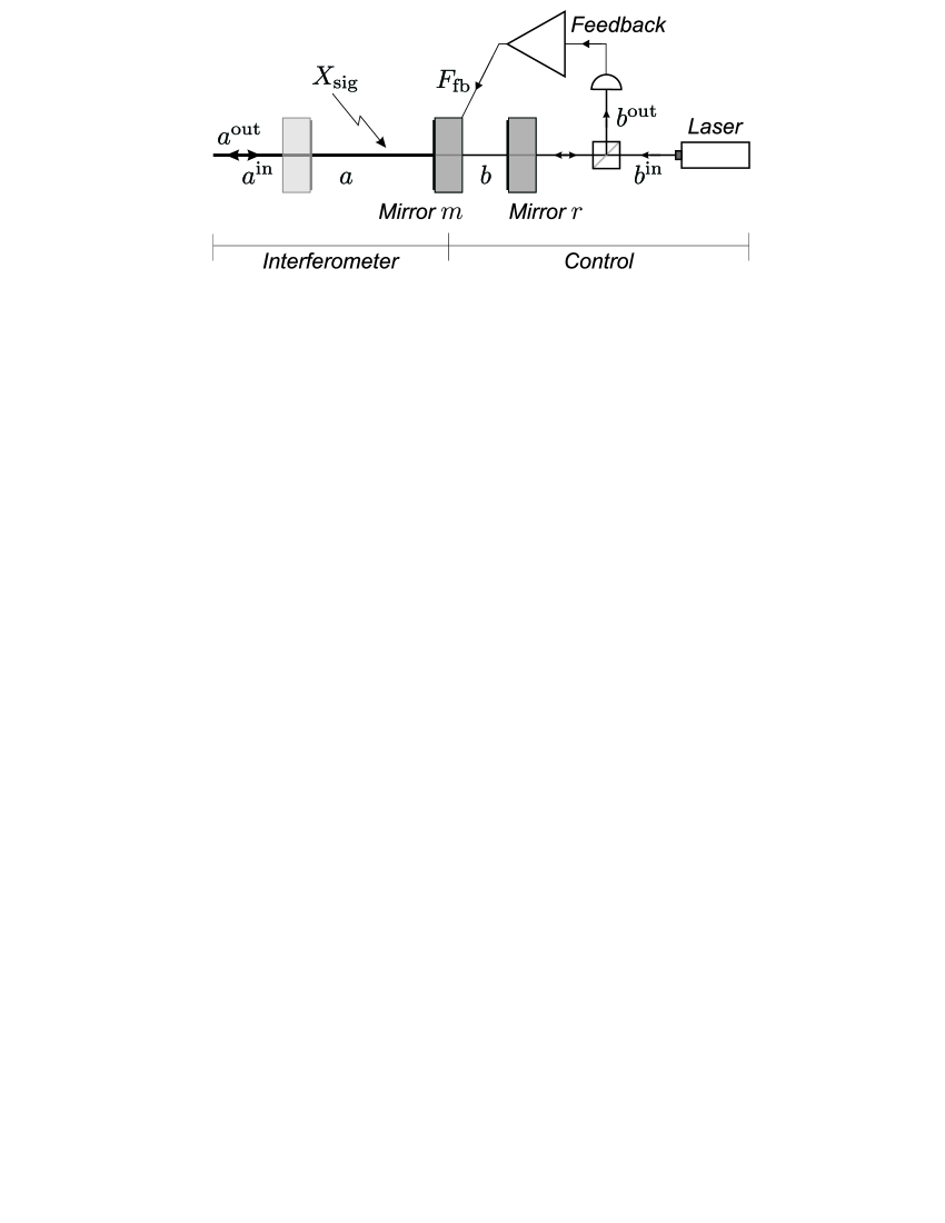
The basic setup is shown in Fig. 1. The interferometric measurement is made by a single Fabry-Perot cavity which can be considered as one arm of a gravitational-wave detector. The signal induces a variation of the cavity length which is detected by sending a light field in the cavity. We focus on the active control of a single mirror of the cavity, namely, the end mirror in Fig. 1. The mirror motion is measured by a second light beam interacting with a short cavity made of the mirror and a reference mirror The result of the measurement is used to apply a correcting force on the mirror.
The ultimate sensitivity of a gravitational-wave interferometer is determined only by quantum noise of light. Classical noises such as seismic or thermal noises can in principle be eliminated and will not be considered in the following. Quantum fluctuations of field at frequency are described by the quantum annihilation operator , whereas the mean field is given by a complex amplitude normalized in such a way that corresponds to a photon flux Reynaud92 . For a lossless single-ended cavity resonant with the laser field, the incident, intracavity, and output mean field amplitudes can be taken as real. It is then convenient to describe quantum fluctuations by the amplitude and phase quadratures and corresponding to the real and imaginary parts of the operator ,
| (1) | |||||
| (2) |
Noise spectra of incident quadratures and for an incident coherent state are
| (3) |
where is defined as the quantum average of the symmetrized product of operators and ,
| (4) |
For frequency smaller than the cavity bandwidth, the amplitude quadrature is left unchanged by the cavity (), whereas the input-output phase shift is proportional to the variation of the cavity length ( is the displacement of mirror )Courty01 ,
| (5) |
The optomechanical coupling parameter is related to the intracavity mean field amplitude , to the cavity finesse and to the wavevector of the light,
| (6) |
The interferometric measurement provides an estimator of the signal obtained by a normalization of the output phase as a displacement [eq. (5)]. is the sum of the signal and extra noise terms,
| (7) |
The first noise term is related to the incident phase noise , and the second corresponds to unwanted variations of the cavity length through the motion of mirror .
The determination of the interferometer sensitivity thus requires one to know the motion of mirror . For a free interferometer (no control cavity and no feedback) the evolution of the velocity is governed by the radiation pressure of the intracavity field whose fluctuations can be expressed in terms of the incident amplitude quadrature ,
| (8) |
where is the mechanical impedance of mirror . In the frequency band relevant for a gravitational-wave interferometer, the suspended mirror can be considered as a free mass with a mechanical impedance related to the mirror mass by
| (9) |
The sensitivity of the measurement is described as an equivalent input noise equal to the spectrum of noises added in the estimator [eq. (7)]. For a coherent input light one gets
| (10) |
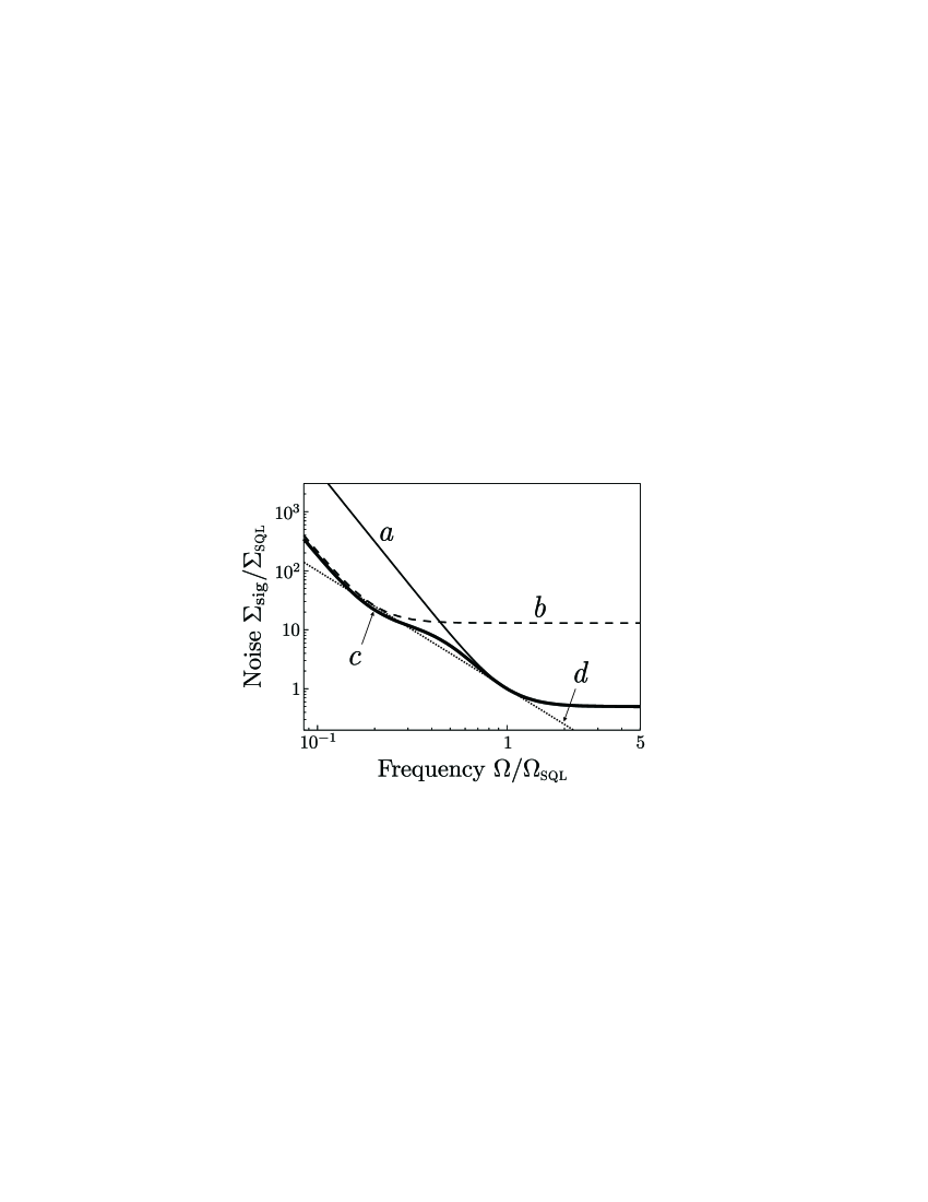
The first term is a measurement error due to phase noise, and the second term corresponds to the mirror motion induced by radiation pressure. As shown in curve a of Fig. 2, phase noise is dominant at high frequency with a flat frequency dependence, whereas radiation pressure is dominant at low frequency with a dependence. To reach a good sensitivity at high frequency one has to choose a large optomechanical parameter , but the analysis bandwidth is reduced at low frequency by the increase of radiation pressure.
For a given optomechanical coupling the sensitivity is optimized only at a frequency where contributions of both noises are equal. This optimization leads to the so-called standard quantum limit (sql) given by
| (11) | |||||
| (12) |
corresponds to the minimum noise reachable at a given frequency by a proper choice of the optomechanical coupling (curve d of Fig. 2).
The addition of a feedback loop allows one to suppress radiation-pressure effects by freezing the motion of mirror . The measurement with the control cavity, of course, has its own quantum limit which has to be taken into account in a quantum analysis of the controlled interferometer, as well as the motion of the reference mirror induced by the radiation pressure of beam . The control cavity indeed measures the position of mirror with respect to the position of the reference mirror . The phase shift at the output of cavity is given by
| (13) |
with an optomechanical parameter for cavity defined in the same way as [eq. (6)].
The measurement of the output phase provides an estimator for the motion of mirror , proportional to the output quadrature and normalized as a velocity. We choose a feedback force applied on mirror proportional to this estimatorCourty01 ,
| (14) |
where is the transfer function of the feedback loop.
The motion of mirror now depends on radiation pressures from both cavities and on the feedback force, whereas the motion of mirror depends only on the radiation pressure of field ,
| (15) | |||||
| (16) |
where is the mechanical impedance of mirror . The resulting motion of mirror is obtained from Eqs. (13) to (15),
| (17) | |||||
Combined with Eqs. (7) and (16) one gets the estimator for the interferometric measurement with feedback,
| (18) | |||||
The first effect of the control is to change the dynamics of mirror by adding a feedback-induced impedance to the free mechanical impedance [compare left parts of eqs. (8) and (17)]. The influence of radiation-pressure effects due to the interferometer is modified both for the mirror velocity and the signal estimator. The associated noise [term proportional to quadrature in eq. (18)] is reduced for a large feedback gain, without changing the phase noise (term proportional to quadrature ).
The second effect of the control is to add fluctuating forces to mirror . The second term in Eq. (17) corresponds to the radiation pressure of beam acting on mirror . The last terms are associated with the presence of the feedback loop and correspond to noises in the control measurement, due to either the phase noise of beam (term proportional to ) or the motion of the reference mirror . As a consequence, the estimator exhibits additional fluctuations related to the incident quadratures and of beam .
We show now that it is possible to adapt both the optomechanical coupling of the control cavity and the feedback gain in order to obtain a large increase of the interferometer sensitivity. The optimization relies on a complete elimination of the radiation-pressure noise due to the interferometer.
The underlying mechanism can be understood in the limit of a very large feedback gain () in which case the error signal of the feedback loop is reduced to zero. Apart from the phase noise of beam , the mirror is then locked on the reference mirror [see eq. (13)] and its residual motion no longer depends on radiation pressure in the interferometer. It is related only to error noises in the measurement by the control cavity.
The equivalent input noise of the interferometric measurement is obtained from Eq. (18),
| (19) |
It only exhibits the phase noises of both beams and radiation-pressure effects on the reference mirror . The locking of mirror leads to a transfer of quantum noise from the control measurement to the interferometric one. The two last terms in Eq. (19) indeed correspond to the equivalent input noise for the measurement by the control cavity [compare to eq. (10) with replaced by and by ].
This quantum transfer is shown in curve b of Fig. 2, obtained with a reference mirror of same mass as the mirror () and with an optomechanical parameter equal to . At low frequency where radiation-pressure noise is dominant, the mirror reproduces the motion of the reference mirror induced by radiation pressure of beam . Since the control measurement is less sensitive (), radiation-pressure effects of beam are smaller than the ones of beam and the transfer of quantum noise leads to a clear reduction of noise. As compared to the free interferometer case (curve a), the equivalent input noise is reduced at low frequency by a factor equal to in Fig. 2 and which can be freely adjusted by changing the intensity of beam .
For an infinite feedback gain this behavior is offset by the phase noise at high frequency which is increased by the reverse factor. The frequency dependence of the noise is thus similar to the free interferometer case except that it is displaced along the standard quantum limit.
The loss of sensitivity at high frequency can easily be avoided by using a frequency dependent feedback gain. For a finite gain the equivalent input noise is given by
| (20) | |||||
The feedback gain can be adapted in such a way that the control is active at low frequency, whereas it plays no significant role at high frequency. It is then possible to have an important reduction of radiation-pressure effects by quantum transfer without losing the high sensitivity of the interferometric measurement at frequencies where it is limited by phase noise. Focusing on the case of two mirrors of equal masses (), one can derive the optimum feedback gain which gives the minimum noise at every frequency,
| (21) | |||||
| (22) |
is large at low frequency and quickly decreases for frequencies larger than . Apart from a factor , this cutoff frequency corresponds to the sql frequency of the control cavity [eq. (11) with replaced by ].
The resulting noise is shown in curve c of Fig. 2. It exhibits a very clear reduction of radiation pressure effects while the limitation by phase noise is identical to the case of a free interferometer. The controlled interferometer is actually equivalent to a free interferometer with a frequency dependent optomechanical coupling equal to at high frequency and to the much smaller value at low frequency. It also compares with a free interferometer whose mirror mass is increased by a factor that is times the weight in the case of Fig. 2.
In the intermediate frequency range between the sql frequencies of the control cavity and of the interferometer, the noise stays near the standard quantum limit and even goes down below. In contrast with the free interferometer for which the standard quantum limit is reached at only one frequency, the sensitivity of the controlled interferometer is very close to the optimum in a large frequency domain between the two sql frequencies.
Finally, note that for a complete interferometer this local control has to be applied to each sensitive mirror of the interferometer, namely, the four mirrors of the Fabry-Perot cavities. The control, however, requires a less sensitive measurement than the interferometer itself, and its implementation seems easy to achieve with currently available technologyRempe92 ; Cohadon99 . Taking, for example, the parameters of the Virgo interferometer ( light power in each Fabry-Perot arms with a global finesse of )Bradaschia90 , the optomechanical parameter of Fig. 2 would correspond to a control cavity of finesse with an incident light power of only.
In a practical implementation the optimum feedback gain has also to be approximated by an electronic transfer function. Although one can use the powerful methods already developed for servo controls in gravitational-wave interferometers, this approximation is not to be stringent since a simple first-order low-pass filter is sufficient to observe the reduction of radiation-pressure noise.
In conclusion, a local control of mirror motion by an optomechanical sensor and a feedback loop allows one to efficiently reduce the radiation-pressure effects in an interferometric measurement. The low frequency sensitivity is improved without alteration in the high frequency domain, thus increasing the interferometer bandwidth. This result shows that active control is a powerful technique to reduce quantum noise. As compared to other methods, an essential characteristic of this control is to be decoupled from other optimizations of the interferometer. Its local implementation does not induce any additional constraint on the interferometer parameters.
References
- (1) C. Bradaschia et al., Nucl. Instrum. Methods Phys. Res. A 289, 518 (1990)
- (2) A. Abramovici et al., Science 256, 325 (1992)
- (3) C.M. Caves, Phys. Rev. D 23, 1693 (1981)
- (4) V.B. Braginsky and F.Ya. Khalili, Quantum Measurement (Cambridge, University Press, 1992)
- (5) M.T. Jaekel and S. Reynaud, Europhys. Lett. 13, 301 (1990)
- (6) K. McKenzie et al., Phys. Rev. Lett 88, 231102 (2002)
- (7) H.J. Kimble et al., Phys.Rev. D 65, 022002 (2002)
- (8) J.M.W. Milatz and J.J. Van Zolingen, Physica XIX, 181 (1953); J.M.W. Milatz, J.J. Van Zolingen and B.B. Van Iperen, Physica XIX, 195 (1953)
- (9) F. Grassia, J.M. Courty, S. Reynaud and P. Touboul, Eur. Phys. J. D 8, 101 (2000)
- (10) H.M. Wiseman, Phys. Rev. A 51, 2459 (1995)
- (11) S. Mancini, D. Vitali and P. Tombesi, Phys. Rev. Lett. 80, 688 (1998)
- (12) P.F. Cohadon, A. Heidmann and M. Pinard, Phys. Rev. Lett. 83, 3174 (1999)
- (13) M. Pinard, P.F. Cohadon, T. Briant and A. Heidmann, Phys. Rev. A 63, 013808 (2000)
- (14) J.M. Courty, A. Heidmann and M. Pinard, Eur. Phys. J. D 17, 399 (2001)
- (15) S. Reynaud, A. Heidmann, E. Giacobino and C. Fabre, in Progress in Optics XXX, ed. by E. Wolf (North-Holland, Amsterdam, 1992), p. 1
- (16) G. Rempe, R.J. Thompson, H.J. Kimble, L. Lalezari, Opt. Lett. 17, 363 (1992)