Optical noise correlations and beating the standard quantum limit in advanced gravitational-wave detectors
Abstract
The uncertainty principle, applied naively to the test masses of a laser-interferometer gravitational-wave detector, produces a standard quantum limit (SQL) on the interferometer’s sensitivity. It has long been thought that beating this SQL would require a radical redesign of interferometers. However, we show that LIGO-II interferometers, currently planned for 2006, can beat the SQL by as much as a factor two over a bandwidth , if their thermal noise can be pushed low enough. This is due to dynamical correlations between photon shot noise and radiation-pressure noise, produced by the LIGO-II signal-recycling mirror.
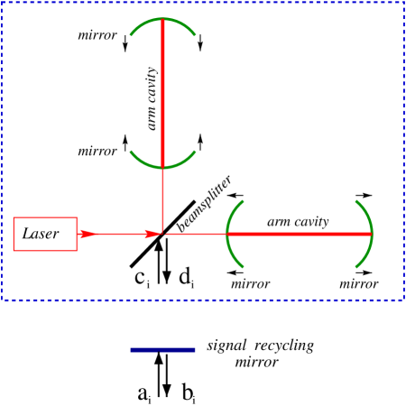
A laser-interferometer gravitational-wave detector (“interferometer” for short) consists mainly of an L-shaped assemblage of four mirror-endowed test masses, suspended from seismic-isolation stacks (see Fig. 1). Laser interferometry is used to monitor changes in the relative positions of the test masses produced by gravitational waves.
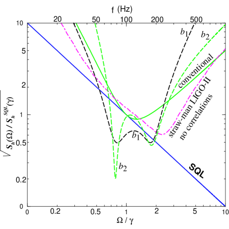
The uncertainty principle states that, if the relative positions are measured with high precision, then the test-mass momenta will thereby be perturbed. As time passes, the momentum perturbations will produce position uncertainties, thereby possibly masking the tiny displacements produced by gravitational waves. A detailed analysis of this process gives rise to the standard quantum limit (SQL) for interferometers: a limiting (single-sided) noise spectral density for the dimensionless gravitational-wave (GW) signal [1]. Here is the mass of each identical test mass, is the length of the interferometer’s arms, is the time evolving difference in the arm lengths, is the GW angular frequency, and is Planck’s constant. This SQL is shown in Fig. 2 for the parameters of LIGO-II [2] [the second generation interferometers in Laser Interferometer Gravitational Observatory (LIGO), planned to operate in –2009]: kg, km. The “straw-man” design for LIGO-II [3], assuming (naively) no correlations between photon shot noise and radiation-pressure noise, is capable of going very close and parallel to the SQL over a wide frequency band: Hz to Hz (see Fig. 2).
Braginsky, who formulated the concept of SQL’s for high-precision measurements [4], also demonstrated that it is possible to circumvent SQL’s by changing the designs of one’s instruments [4], [5]. Since the 1970s, it has been thought that for GW interferometers the redesign must be major — e.g., injecting squeezed vacuum into an interferometer’s dark port [6] and/or introducing 4km-long filter cavities into the interferometer’s output port, as has recently been proposed for LIGO-III [7] to implement frequency-dependent homodyne detection [8]. Yuen and Ozawa have also conceived ways to beat the SQL by taking advantage of the so-called contractive states [9], but it is not yet clear how to implement their ideas in real GW interferometers.
In this paper we show that although major redesigns could not ba avoided if we want to beat the SQL significantly, however LIGO-II interferometers with their currently planned design, can beat the SQL by modest amounts (see, e.g., noise curves and in Fig. 2), if all sources of thermal noise can also be pushed below the SQL. For current LIGO-II designs, estimates place the dominant, thermoelastic component at about the SQL [10].
As is well known, there are two aspects of the uncertainty principle: (i) the quantum mechanics of the test-mass wave function, and (ii) the Heisenberg-microscope-like influence of the laser light used to measure the position. Braginsky and colleagues [5, 11] have shown that the test-mass wave-function aspect of the uncertainty principle is irrelevant to the operation of a GW interferometer. Indeed, the interferometer does not measure relative test-mass positions; it only monitors classical-force-induced changes in the relative positions, and those changes, in the LIGO frequency band, are not contaminated by the details of the test-mass wave functions. As a result, the light is the only enforcer of the SQL.
Braginsky and Khalili have also shown that [5] as long as there are no correlations between the light’s shot noise and its radiation-pressure-fluctuation noise, the light firmly enforces the SQL. This is the case for “conventional interferometers”, i.e. for interferometers that have no signal-recycling mirror on the output port and a simple (frequency independent) homodyne detection is performed (the type of interferometer used, e.g., in LIGO-I/Virgo). However, the signal-recycling mirror [2] (which is being planned for LIGO-II as a tool to reshape the noise curves ***A power-recycling mirror is also used in real interferometers to increase the light power at the beamsplitter, but it will not affect the quantum noise in the dark-port output. For this reason we do not take it into account.), sends back into the arm cavities the signal coming out from the dark port and thereby produces shot-noise / back-action-noise correlations, which break the light’s ability to enforce the SQL. These dynamical correlations arise naturally from the nontrivial coupling between the antisymmetric mode of motion of the four arm-cavity mirrors and the signal recycled optical fields [12]. This coupling invalidates the naive picture, according to which the arm cavity mirrors behave like free test masses subject only to Poissonian quantum-vacuum fluctuations. As we show below, the interferometer as a whole responds to a GW signal as an “optical spring” and this oscillatory behaviour is responsible for the resonant amplification of the GW signal and the beating of the SQL. Braginsky, Gorodetsky and Khalili [14], in designing the “optical bar” GW detectors, were the first to suggest that this phenomenon could be used to reach sensitivities beyond the free-mass SQL. The resonant dips in Fig. 2 correspond to the resonant frequencies of the two dimensional dynamical system formed by the arm-cavity mirrors and the signal-recycled optical field. Hence, the SR interferometer’s dynamics cannot be described by a successive sequence of independent measurements of the test-mass displacements, for which the SQL was originally derived [4] and further discussed [9]. On the contrary, the SQL for a free test mass is no longer relevant for SR interferometers. Its only remaining role is as a reminder of the regime where back-action noise is comparable to the shot noise. The remainder of this paper is devoted to explaining these claims. The full details will be published elsewhere [12, 13].
Kimble, Levin, Matsko, Thorne and Vyatchanin have recently derived the input-output relations for a conventional interferometer [7] using the Caves-Schumaker two-photon formalism [15]. The full electric field, in the Heisenberg picture, at the output (dark) port, i.e. soon after the beamsplitter (see Fig. 1), reads:
| (2) | |||||
where and are the two output quadratures (see Fig. 1), is the carrier angular frequency, is the effective cross sectional area of the laser beam and is the speed of light. Indicating by and the two input quadratures at the dark port, the input-output relations, at side-band (gravity-wave) angular frequency , are [7]:
| (3) |
where is the net phase gained by the field at sideband frequency while in the arm cavity, is the half bandwidth of the arm cavity ( is the power transmissivity of the input mirrors); is the Fourier transform of the GW field, and is the SQL for GW detection. The quantity in Eq. (2) is the effective coupling constant which relates the motion of the test mass to the output signal. Finally, is the input light power at the beamsplitter, while is the power needed by a conventional interferometer to reach the SQL. We indicate by the length of the SR cavity and limit our analysis to a SR cavity much shorter than the arm cavities, e.g., . We introduce , the phase gained by the carrier while traveling one way in the SR cavity.
Propagating the electric field (2) down to the SR mirror and introducing the input and output quadratures and () for the entire SR interferometer (Fig. 1), we obtain the final input-output relations [12]: ††† Here we face a delicacy of the Fourier-based formalism due to possible unstable modes of the system. We cured the problem by introducing an appropriate control system which leaves the expression of the noise spectral density unchanged [12, 13].
| (4) |
where, to ease the notation, we have defined:
| (5) | |||
| (6) | |||
| (7) | |||
| (8) |
In the above equations and are the amplitude reflectivity and transmissivity of the SR mirror, respectively. For a lossless SR mirror: . Because in Eq. (4) represent a free field, they satisfy the usual commutation relations for quadratures with [15].
We assume a frequency-independent quadrature is measured via homodyne detection, and the noise is calculated as follows [7]. We define , where is the noise part of , and then the (single-sided) spectral density of , with , can be computed by the formula: . Assuming that the input is in its vacuum state, we find [12] that the noise spectral density can be written in the simple form (note that ):
| (9) | |||
| (10) |
Fig. 2 shows this for the two quadratures (i.e. ) and (), with (for definiteness) , and . Also shown for comparison are the SQL, and for a straw-man LIGO-II design when the shot-noise/radiation-pressure correlations are (naively) ignored [3], and for a conventional interferometer with . The sensitivity curves for the two quadratures go substantially below the SQL and show an interesting resonance structure. To explain the resonant frequencies in the case of a highly-reflecting SR mirror, we have found it convenient to investigate the free oscillation modes of the entire interferometer. By free we mean no GW signals [] and perfect reflectivity for the SR mirror (). The free-oscillation frequencies satisfy the relation [12, 13]: , which can be solved to give , which agrees quite accurately with the frequencies of the valleys in the dashed noise curves () of Fig. 2. For very low light power () the resonant frequencies decouple into: , i.e. the eigenfrequency of a free mass and , i.e. the optical resonances of a SR interferometer with fixed arm-cavity mirrors [2]. By increasing the light power up to , the test masses and the optical field get more and more coupled, and the resonant frequencies of the entire system become a “mixture” of the two decoupled resonances. It is easy to show [12, 13] that the low-frequency resonant dip in Fig. 2 originates from the free-mass eigenfrequency , modified by the dependence of the radiation-pressure force on the test-mass motion’s history; while the higher-frequency resonant valley is largely due to the optical field resonances . Hence, the SR mirror feeds back the signal into the arm cavities and makes the SR interferometer behave as an “optical spring” detector. The GW device gains sensitivity near the resonant frequencies.
To give a first rough idea of the performances that a SR interferometer with homodyne detection can reach if thermal noise can be made negligible, we have estimated the signal-to-noise ratio [1] for gravitational waves from binary systems made of black holes and/or neutron stars. Using the Newtonian, quadrupole approximation for which the waveform’s Fourier transform is , and introducing in the above integral a lower cutoff due to seismic noise at (), we get for the parameters used in Fig. 2: and . These numbers refer to the first and second quadratures, respectively. Here is the signal to noise ratio given by a conventional interferometer with the same light-power input at the beamsplitter, which is SQL-bounded.
We now briefly discuss how optical losses affect the noise in a SR interferometer. We have computed [12] the influence of losses using (i) the lossy input-output relations [analog of Eq. (3)] for a conventional interferometer [boxed part of Fig. 1] as derived in [7], and (ii) an analogous treatment of losses in the SR cavity. We find that for loss levels expected in LIGO-II [3], the optical losses have only a moderate influence on the noise curves of Fig. 2; primarily, they just smooth out the deep resonant valleys. More specifically, for (i) the physical parameters used in Fig. 2, (ii) a net fractional photon loss of 1% in the arm cavities and 2% in each round trip in the SR cavity, and (iii) a photodetector efficiency of 90%, we find a fractional loss in for inspiraling binaries of and , for the first and second quadratures, respectively.
In the last part of this letter we discuss the role played by the shot-noise / radiation-pressure correlations, present in LIGO-II’s noise spectral density (9), in beating the SQL. Our analysis is based on the general formulation of linear quantum measurement theory developed by Braginsky and Khalili in [5]. Quite generically [5, 13], we can rewrite the output of the whole optical system as: . Here by output we mean one of the two quadratures , or a combination of them, e.g., (modulo a normalization factor). in the above equation is the susceptibility of the antisymmetric mode of motion of the four mirrors [5], given by ; is the effective‡‡‡ We refer to and as effective because we have shown [13] that for a SR interferometer the real force acting on the test masses is a combination of these effective fields. When the shot noise and radiation-pressure-noise are correlated, the real force does not commute with itself at different times [13], which makes the analysis in terms of real quantities more complicated than in terms of the effective ones. output noise field and is the effective back-action force, both of these operators do not depend on the mirror mass . The noise spectral density reads [5]:
| (11) |
where the (one-sided) cross correlation of two operators is defined by . Due to their dependence on the terms containing , and in Eq. (11) should be identified as the spectral densities of the effective shot noise, back-action noise and a term proportional to the effective correlation between the two noises [5]. From the definition of spectral density, one can derive [5, 12] the following uncertainty relation for the (one-sided) spectral densities and cross correlations of and : . It turns out that this equation does not impose in general a lower bound on the noise spectral density (11). However, in a very important type of interferometer it does, namely for interferometers with uncorrelated shot noise and back-action noise, e.g., a LIGO-I/Virgo type conventional interferometer. In this case [7] and inserting the vanishing correlations into Eq. (11) and into the uncertainty relation, one easily finds that . From this it follows that to beat the SQL one must build up correlations between shot noise and back-action noise. In a SR interferometer the arm-cavity light containing the GW signal and the quantum-vacuum fluctuations enters the SR cavity through the dark port (see Fig. 1). Part of this light leaks out through the SR mirror and contributes to the shot noise, but another portion, which is correlated to it, is fed back into the arm cavities and contributes to the radiation-pressure noise at some later time. This mechanism not only originates the nontrivial coupling between the antisymmetric mode of motion of the four arm-cavity mirrors and the signal-recycled optical field, which we discussed above, but also builds up dynamical correlations between the shot-noise and the radiation-pressure noise. Indeed, we obtain: (see Ref. [12] for their explicit expressions).
In conclusion, our analysis has demonstrated the importance of using fully quantum techniques to analyze SR interferometers with LIGO-II parameters, where the correlations between the shot and radiation-pressure noises are significant. It also revealed the crucial role of the coupled optical-mechanical dynamics in producing such correlations. It is now important to identify the best SR configuration, i.e. the choice of the physical parameters , , , , and the readout scheme (homodyne or modulation/demodulation) that optimizes the for various astrophysical GW sources.
The authors thank K.S. Thorne for having introduced us to QND theory, for his constant encouragement and for very fruitful discussions and comments, and V.B. Braginsky, F. Ya. Khalili, Y. Levin and K.A. Strain for very helpful discussions and comments. This research was supported in part by NSF grant PHY-9900776 and for AB also by the Richard C. Tolman Fellowship.
REFERENCES
- [1] K.S. Thorne, in Three Hundred Years of Gravitation, eds. S.W. Hawking and W. Israel, (Cambridge, 1987), p. 330.
- [2] R. Drever, in Gravitational Radiation, ed. N. Deruelle and T. Piran (North-Holland, Amsterdam, 1983), pp. 321-338; B.J. Meers, Phys. Rev. D 38 (1988) 2317; J.Y. Vinet, B. Meers, C.N. Man and Brillet, Phys. Rev. D 38 (1988) 433; J. Mizuno, K.A. Strain, P.G. Nelson, J.M. Chen, R. Schilling, A. Rüdiger, W. Winkler and K. Danzmann, Phys. Lett. A 175 (1993) 273; J. Mizuno, PhD thesis (1995).
- [3] E. Gustafson, D. Shoemaker, K. Strain and R. Weiss, LIGO Document Number T990080-00-D.
- [4] V.B. Braginsky, Sov. Phys. JETP 26 (1968) 831; V.B. Braginsky and Yu.I. Vorontsov, Sov. Phys. Uspekhi 17 (1975) 644; V.B. Braginsky, Yu.I. Vorontsov and F.Ya. Kahili, Sov. Phys. JETP 46 (1977) 705.
- [5] V.B. Braginsky and F.Ya. Khalili, Quantum measurement, ed. K.S. Thorne (Cambridge, 1992).
- [6] C.M. Caves, Phys. Rev. D 23 (1981) 1693; W. G. Unruh, in Quantum Optics, Experimental Gravitation, and Measurement Theory, eds. P. Meystre and M.O. Scully (Plenum, 1982), p. 647; M. T. Jaekel and S. Reynaud, Europhys. Lett. 13 (1990) 301.
- [7] H.J. Kimble, Y. Levin, A.B. Matsko, K.S. Thorne and S.P. Vyatchanin, [gr-qc/0008026].
- [8] S.P. Vyatchanin and A.B. Matsko, JETP 77 (1993) 218; S.P. Vyatchanin and E.A. Zubova, Phys. Lett. A 203 (1995) 269; S.P. Vyatchanin and A.B. Matsko, JETP 82 (1996) 1007; ibid. JETP 83 (1996) 690; S.P. Vyatchanin, Phys. Lett. A 239 (1998) 201.
- [9] H.P. Yuen, Phys. Rev. Lett. 51 (1983) 719; C. M. Caves, Phys. Rev. Lett. 54 (1985) 2465; M. Ozawa, Phys. Rev. Lett. 60 (1988) 385; Phys. Rev. A 41 (1990) 1735; J. Maddox, Nature 331 (1988) 559.
- [10] V.B. Braginsky, M.L. Gorodetsky and S.P. Vyatchanin, Phys. Lett. A 264 (1999) 1; Y.T. Liu and K.S. Thorne, Phys. Rev. D 62 (2000) 122002.
- [11] V.B. Braginsky, M.L. Gorodetsky, F.Ya. Khalili, A.B. Matsko, K.S. Thorne, S.P. Vyatchanin, in preparation.
- [12] A. Buonanno and Y. Chen, Quantum noise in second generation, signal-recycled laser interferometric gravitational-wave detectors, GRP/00/553, accepted for publication in Phys. Rev. D [gr-qc/0102012].
- [13] A. Buonanno and Y. Chen, Signal recycled laser-interferometer gravitational-wave detectors as optical springs, GRP/00/554, submitted to Phys. Rev. D, [gr-qc/0107021].
- [14] V.B. Braginsky, M.L. Gorodetsky and F.Ya. Khalili, Phys. Lett. A 232 (1997) 340; V.B. Braginsky and F.Ya. Khalili, Phys. Lett. A 257 (1999) 241.
- [15] C.M. Caves and B.L. Schumaker, Phys. Rev. A 31 (1985) 3068; B.L. Schumaker and C.M. Caves, Phys. Rev. A 31 (1985) 3093.