Demonstration of detuned dual recycling at the Garching 30 m laser interferometer
Abstract
Dual recycling is an advanced optical technique to enhance the signal-to-noise ratio of laser interferometric gravitational wave detectors in a limited bandwidth. To optimise the center of this band with respect to Fourier frequencies of expected gravitational wave signals, detuned dual recycling has to be implemented. We have demonstrated detuned dual recycling on a fully suspended 30 m prototype interferometer. A control scheme that allows the detector to be tuned to different frequencies will be outlined. Good agreement between the experimental results and numerical simulations has been achieved.
keywords:
Dual recycling \sepMichelson interferometer \sepGravitational wave detector \PACS04.80.Nn \sep07.60.Ly \sep42.25.Hz \sep95.55.Ym1 Introduction
Several long-baseline laser interferometers are currently under construction worldwide, aimed at the direct detection of gravitational waves [1, 2, 3, 4, 5]. These instruments are basically Michelson interferometers optimised to measure tiny differential phase modulations of the light in the two arms, which would be the main effect of a passing gravitational wave. In order to reduce the effect of the photon shot-noise, which is one of the main noise sources in these detectors, the established technique of power recycling is used to maximise the light power circulating in the arms. The sensitivity can be further improved by optimising the signal storage time, i.e. the average time for which the phase modulation sidebands induced by the gravitational wave are stored in the interferometer. For this purpose the advanced techniques of signal recycling and resonant sideband extraction have been proposed and demonstrated on prototypes [6, 7].
One of the proposed features of signal recycling is the possibility to detune the detector in a way that allows the frequency of the sensitivity maximum to be set to an arbitrary non-zero value. This is useful in order to optimise the sensitivity for the detection of signals at a predetermined frequency. To use a technique like detuned signal recycling in a gravitational wave detector a control scheme has to be developed. A method is required (combining optical and electronical techniques) to produce error signals for the microscopic position (within a small fraction of a wavelength) of each mirror, which can be used in feedback loops to set and maintain the desired operating point of the interferometer. For best versatility the control scheme should include the broadband state (see below) as well as the full intended detuning range. It should provide an easy way to change the detuning, so that an electronic servo can be used to adjust the amount of detuning (and hence the frequency of the sensitivity maximum) during operation of the detector. This paper describes a control scheme that offers these advantages for the dual recycling system which will be used in GEO 600. For a more general description of the 30 m prototype with dual recycling see [6] and [8].
2 Recycling techniques
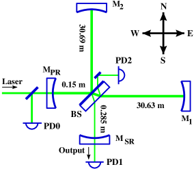
The Michelson interferometer (consisting of , and ) is operated at the dark fringe in which case the light of the carrier frequency is reflected back towards the West (we labelled the different ports of the Michelson interferometer North, South, East, and West, see Fig. 1) and ideally never reaches the South port. A passing gravitational wave (or a differential motion of the end mirrors and ) will modulate the phase of the light in the interferometer arms and thus create ‘signal sidebands’, which are not directed to the West but to the South port. The signal can then be detected in the light intensity in the South port. This is the main interferometer output signal.
Both signal recycling and resonant sideband extraction employ an additional mirror at this Michelson interferometer output port (see Fig. 1). For the signal sidebands a cavity (the signal recycling cavity) is formed by and the Michelson interferometer. Note that in the dark fringe condition the Michelson interferometer behaves like a mirror if seen from both the West and South ports. In the nominal operating point the bandwidth of the interferometer with signal recycling is determined by the reflectivity of , when all losses inside the interferometer are smaller than the transmission of . There are three possible modes of operation of the signal recycling cavity, which are distinguished by the microscopic position of . We describe that position by the ‘detuning’ , defined by
| (1) |
where is the average distance between and the two end mirrors , (see Eq. 3 and Fig. 3) and refers to the carrier wavelength. The three modes of operation are:
-
1.
In broadband signal recycling, is tuned such that the carrier frequency is resonant in the signal recycling cavity (). The sensitivity is enhanced for low Fourier frequencies, at the expense of reducing the bandwidth to the range from DC to , where is the FWHM bandwidth of the signal recycling cavity.
-
2.
In resonant sideband extraction, the signal recycling cavity is tuned to anti-resonance for the carrier frequency (), which results in a wider bandwidth than that of the instrument without . This scheme is useful only for detectors with Fabry-Perot cavities in the arms and when the arm cavity bandwidth is made as narrow as technically possible in order to maximise the energy stored in the arms.
-
3.
Both signal recycling and resonant sideband extraction have, apart from their standard mode of operation described above, a so-called detuned mode that has a sensitivity maximum at a selectable non-zero Fourier frequency. Those modes are characterised by . The width of the sensitivity peak is given by . Detuned recycling thus creates the possibility of tuning the detector to the exact frequency of an expected periodic signal or even of tracking a changing periodic signal (chirp). Figure 2 shows several computed transfer functions (gravitational wave signal detector output) for detuned and broadband dual recycling.

Signal recycling in combination with power recycling was proposed by Meers [9] and is called dual recycling. The first experimental demonstration was performed on a table-top setup by Strain et al. [10]. Further table-top experiments have investigated various control schemes [11, 12]. Dual recycling will be used from the beginning in the British-German project GEO 600 whilst also being considered for implementation in the further stages of various other gravitational wave detectors. Recently the first experimental demonstration of dual recycling on a fully suspended interferometer at the 30 m prototype in Garching has been reported [6]. Subsequently, we have operated the 30 m prototype in a detuned dual recycling mode. That will be the subject of this paper, and special emphasis will be given to the control scheme, which can be extended for use in the gravitational wave detectors currently being built.
Although some features of the dual recycled interferometer can be predicted by simple models, the general properties of such a system are very complex. Therefore a computer model has been developed [14, 15] which allows the computation of transfer functions and error signals of a complex optical system like a dual recycled interferometer. The interferometer is simulated by solving a set of time independent linear equations that represents the quasistatic light fields inside the interferometer in the ray optics formalism. The simulation has been used to model error signals and transfer functions and is also used to choose suitable operating points of a dual recycled interferometer.
3 Control signals
The dual recycled interferometer consists of 4 mirrors and the beam splitter. The three degrees of freedom that have to be controlled by electronic control systems to keep the interferometer at its operating point are (see Fig. 3):
-
1.
the length of the power recycling cavity
(2) -
2.
the length of the signal recycling cavity
(3) -
3.
the differential arm length of the Michelson interferometer
(4)
The length of the power recycling cavity can be controlled using a standard Pound-Drever-Hall method [16]. The control of the Michelson interferometer and the signal recycling cavity length is more complicated and depends on whether the system should be set to the detuned mode or the broadband mode. The control scheme described here makes use of a modulation technique that was originally proposed by Schnupp [13]: an RF phase modulation is applied to the light before it enters the interferometer, and a macroscopic arm length difference causes some fraction of the modulation sidebands to appear at the dark fringe (South) port where they act as local oscillator for the detection of the gravitational wave signal. To distinguish these RF phase modulation sidebands used for controlling the interferometer from the sidebands induced by a gravitational wave, the former will be called Schnupp sidebands in the following.
The state of the Michelson interferometer can be expressed by the differential microscopic detuning of the arm length difference, defined by:
| (5) |
In our case corresponds to the dark fringe condition, the nominal operating point of all experiments discussed here. Similarly, refers to the state of the signal recycling cavity when the carrier light is on resonance in this cavity (broadband signal recycling mode).
Broadband recycling control signals can be understood with an intuitive model in which the interferometer contains two coupled cavities (the signal recycling and power recycling cavity) resonant for the carrier frequency. In the dark fringe condition, ideally the carrier light only is present in the power recycling cavity and never reaches the signal recycling mirror, whereas the signal sidebands are circulating only in the signal recycling cavity. With broadband recycling the resonance of the signal recycling cavity is centered on the carrier frequency, and for signal frequencies within the SR cavity bandwidth both signal sidebands are resonantly enhanced.
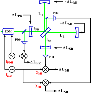
Simulations show that suitable error signals for the length control system of the Michelson interferometer and the signal recycling cavity can be obtained from the light in the South port and light split off from one of the interferometer arms respectively (e.g. using the demodulated photocurrent of PD1 and PD2 in Fig. 3). If the Michelson fluctuates around its operating point , some carrier light leaves the interferometer at the South port. Beating this light with the Schnupp modulation sidebands thus generates an error signal at PD1 after demodulation. Similarly, sidebands induced by a gravitational wave are directed to the South port and generate a detectable signal. The South port is then the main output of the interferometer, and PD1 provides the gravitational wave signal as well as the error signal for the Michelson control.
When the tuning of the signal recycling mirror changes, the Schnupp modulation sidebands experience a phase shift, which can only be detected by beating with the carrier light which is not present in the South port but in the rest of the interferometer. This beat signal supplies an error signal that can be detected either in the West, East, or North port (it was detected by PD2 in our experiment).

The macroscopic arm length difference of the Michelson interferometer determines the amplitude of the Schnupp sidebands transferred from the power recycling cavity into the signal recycling cavity. Ideally the shot noise limited sensitivity of the Michelson interferometer to gravitational wave signals is independent of the amplitude of the Schnupp sidebands reaching the South port. In real systems it is necessary that the modulation sidebands dominate the light in the interferometer output, i.e. the light power of the sidebands must be larger than the light power of higher transverse modes leaving the interferometer due to imperfections of the beam splitter and mirrors.
Detuned recycling demands a different resonance condition in the signal recycling cavity. Often only one signal sideband is resonantly enhanced, whereas the gain for the other sideband can be very low. Hence for greater detunings one signal sideband can be neglected, and the maximum sensitivity of the detuned interferometer is half the sensitivity of the interferometer in the broadband case at DC (assuming the same reflectivity for ). Since the resonance frequency of the signal recycling cavity now differs from that of the power recycling cavity, the Schnupp modulation sideband throughput is more complex; thus the simple two-cavity model is no longer valid. Therefore the computer model was used to find control signals for the operating point of the Michelson and the new operating point for the signal recycling mirror, preferably by using only one Schnupp modulation frequency.

The basic idea is to use the same photo detectors (i.e. PD1 and PD2) but to shift the Schnupp modulation frequency by an offset of approximately (the frequency of the sensitivity maximum) compared with the broadband case (see Fig. 4). For example, if the Schnupp modulation frequency in the broadband case was , the new Schnupp modulation frequency for an expected signal frequency of 100 kHz would be . (With the free spectral range of the signal recycling cavity of the detuning to corresponds to an operating point of ). Figure 5 shows the computed error signals for such a setup. This modulation frequency gives the steepest slope and widest locking range for the signal recycling control but results in a narrow locking range for the Michelson. Reducing the frequency shift improves the Michelson locking range with a slightly lower discriminator slope for the signal recycling mirror.

One feature of the discussed control scheme is that the operating point of the signal recycling cavity is determined by both the Schnupp modulation frequency and the demodulation phase that is used to generate the signal recycling error signal. Figure 6 shows the dependence of the signal recycling error signal on . By varying by rad the zero crossings move between 0.0594 rad and 0.0722 rad, which corresponds to sensitivity peaks between 92 kHz and 111 kHz. Thus the rough tuning is determined by the shift of the modulation frequency, while fine tuning is possible by changing the demodulation phase . Furthermore, the operating point of the interferometer can be continously shifted from broadband mode to any desired detuning by simultaneous adjustments of , and . This feature was used in our experiment.
4 Experimental demonstration of detuned dual recycling
In our experiment, the control signal needed to keep the power recycling cavity resonant to the laser frequency was obtained independently with the standard Pound-Drever-Hall method [16]. An additional reference cavity was used for pre-stabilising the laser frequency (see [8] for a detailed description of the experiment). To keep the setup as simple as possible it is desirable to use only one Schnupp modulation frequency to generate both remaining longitudinal control signals for the Michelson interferometer and the signal recycling mirror. By demodulating the photocurrent of the South port photodetector PD1 with the Schnupp modulation frequency an output signal for controlling the Michelson interferometer is obtained (see Fig. 3).
Using the same Schnupp frequency but the photocurrent from PD2, which detects a weak beam picked off from one interferometer arm, a control signal for the signal recycling mirror is obtained. The mixers used for demodulation are driven by a local oscillator at the Schnupp modulation frequency with the phases and . For the 30 m prototype a Schnupp modulation frequency of was used.
To demonstrate detuned dual recycling the 30 m interferometer was first locked in broadband dual recycling condition. The demodulation phases of the local oscillators and were adjusted for maximum response of the Michelson interferometer error signal at PD1 to a differential arm length test signal.
A transfer function was measured using coil-magnet actuators at the East end mirror to introduce a test signal of known amplitude in the Michelson error signal (measured at photodetector PD1). The ratio between the Michelson error signal and the current through the actuator coils will be called the gain of the interferometer. Then the same actuators were used to apply a test signal of 69 kHz, the next Fourier frequency at which the detuned dual recycling was to be optimised. In order to shift the operating point from broadband to detuned the Schnupp modulation frequency and the demodulation phases were slowly and carefully adjusted for maximum gain, i.e. such that the test signal appeared with maximal amplitude in the error signal of the Michelson interferometer. The best modulation frequency found was . In this state the transfer function of the interferometer was measured. The difference in gain between the two measurements (i.e. the ratio of the two transfer functions) was expected to show the effect of the detuning while cancelling other effects like mechanical mirror resonances. Figure 7 shows the first results obtained. The transfer function shows the expected additional gain of about 5 dB at around 69 kHz. This means that after changing from broadband operation to detuned dual recycling the (test) signal at 69 kHz was detected in the main interferometer output with a 5 dB higher amplitude.

The theoretical curve shown in Fig. 7 was obtained by calculating two transfer functions separately for the conditions of the respective measurements. In the simulation the Schnupp modulation frequency was changed from to , the detuning of the signal recycling mirror () from 0.0 to 0.042 rad, and the demodulation phase of the Michelson () from -0.47 to -0.165 rad. The values for and had been determined beforehand using a non-linear least square optimisation in which the transfer function had been optimised for maximum gain at 69 kHz by only varying and . This computation reflects the experimental procedure.
The good prediction of the measured additional gain around 69 kHz and especially the good agreement of the phase shift shows that the model is correct and that the interferometer was indeed locked in a detuned state.
The locking range for the Michelson can be improved by changing the Schnupp modulation frequency or the Michelson demodulation phase from its optimum value at the expense of having a reduced Michelson interferometer discriminator slope at . Such readjustments can be used to increase the locking range during lock acquisition. Then the demodulation phases can be slowly tuned back to their optimal values with respect to the gain (or discriminator slope) during operation. In principle optimum values for locking range and gain can be achieved simultaneously by applying separate modulation frequencies for the two control systems.
While the additional gain due to the detuning would be much larger in GEO 600, the ratio between detuning and bandwidth is very similar in GEO 600 and our experiment. The bandwidth of the 30 m prototype interferometer, which is defined by the bandwidth of the signal recycling cavity, was about 30 kHz. A typical operation of the GEO 600 detector would use a bandwidth of e.g. 200 Hz and a detuning of around 500 Hz (with a total detuning range of 0 to 1.5 kHz), so that the ratio between the bandwidth and detuning will be very similar to the one used here.
The detuned system behaved similar to the broadband case [6]; given a good initial alignment the lock acquisition happened by itself and the autoalignment system worked as well as before. We also again observed the mode healing effect, which increases the contrast of the Michelson interferometer by a factor of ten.
More measurements were carried out to test different operating points. Using a fixed Schnupp modulation frequency of 9.740 MHz, the detuning was changed from 0.044 to 0.057 rad, corresponding to a shift of the sensitivity peak by 20 kHz. Note that for locking the interferometer to different detuned states only the signal recycling demodulation phase had to be re-adjusted. This might also be done by an electronic servo, which would allow the adjustment of the sensitivity peak of the detector automatically.
The experiment described is the first demonstration of detuned dual recycling with a fully suspended interferometer. The results are in good agreement with numerical simulations. Detuned dual recycling showed the same operational advantages as broadband dual recycling. With the developed control scheme which is fully compatible with the control of the broadband setup, an automated tracking and stabilising of the peak sensitivity of GEO 600 seems possible.
KAS and KDS would like to acknowledge support by PPARC and the University of Glasgow. KDS is also supported by a BP/RSE fellowship. The authors are grateful for help and assistance from the GEO 600 team.
References
- [1] A. Abramovici et al., Science 256 (1992) 325–333.
- [2] C. Bradaschia et al., Nuclear Instruments and Methods in Physics Research A 289 (1990) 518–525.
- [3] K. Danzmann et al., in First Edoardo Amaldi Conference on Gravitational Wave Experiments, Frascati 1994, (World Scientific, Singapore, 1995) 100–111.
- [4] K. Tsubono et al., in ‘Gravitational Wave Detection’, Proc. TAMA Workshop, Saitama, Japan, 1996; ed. by K. Tsubono et al., (Universal Academy Press Tokyo, 1997), 183–191.
- [5] D. Blair et al., in ‘Gravitational Wave Detection’, Proc. TAMA Workshop, Saitama, Japan, 1996; ed. by K. Tsubono et al., (Universal Academy Press Tokyo, 1997).
- [6] G. Heinzel et al., Phys. Rev. Lett. 81 (1998) 5493–5496.
- [7] G. Heinzel et al., Phys. Lett. A 217 (1996) 305–314.
- [8] G. Heinzel: Advanced optical techniques for laser-interferometric gravitational-wave detectors, Ph.D. Thesis, University of Hannover (1999), also available as MPQ report 243.
- [9] B.J. Meers, Phys. Rev. D 38 (1988) 2317–2326.
- [10] K.A. Strain, B.J. Meers, Phys. Rev. Lett. 66 (1991) 1391–1394.
- [11] M.B. Gray et al., Appl. Opt. 37(25) (1998) 5886–5893.
- [12] Three Diploma-theses at University of Hannover: by D. Maass (1995), A. Barthel (1997), A. Freise (1998).
- [13] L. Schnupp, talk at European Collaboration Meeting on Interferometric Detection of Gravitational Waves (Sorrento, 1988).
- [14] J. Mizuno et al., J. Opt. Soc. Am. A 16 7 (1999) 1730–1739.
-
[15]
A. Freise: FINESSE, a frequency domain interferometer simulation (2000)
http://www.mpq.mpg.de/~adf . - [16] D. Schnier et al., Phys. Lett. A 225 (1997) 210–216.