ODP channel objects that provide services transparently for distributing processing systems
Abstract
This paper describes an architecture for a distributing processing system that would allow remote procedure calls to invoke other services as messages are passed between clients and servers. It proposes that an additional class of data processing objects be located in the software communications channel. The objects in this channel would then be used to enforce protocols on client–server applications without any additional effort by the application programmers. For example, services such as key–management, time–stamping, sequencing and encryption can be implemented at different levels of the software communications stack to provide a complete authentication service. A distributing processing environment could be used to control broadband network data delivery. Architectures and invocation semantics are discussed, Example classes and interfaces for channel objects are given in the Java programming language.
1 Distributed Processing Platforms
1.1 RPCs and Connections
A distributed processing platform provides a method of making a Remote Procedure Call, an RPC, almost transparent to the application developer—see, for example, Tivoli[TVL99] and Orbix [ORB99]—the relatively mature industry standard for both of which is the Common Object Request Broker Architecture, CORBA, from the Object Management Group[OMG98], OMG; this defines an Object Request Broker, ORB, which is an infrastructure for RPCs.
Recently Sun Microsystems [SUN98d] have enhanced the Remote Method Invocation package, java.rmi, for Java [SUN98c] as part of the Java Development Kit, JDK, 1.2. It now allows connections to be created between a client and a server which can have a different data transfer representation [SUN98a]. As pointed out in the documentation for this feature, this is particularly suitable for implementing the Secure Socket Layer, SSL, [FKK95] and could also be used to implement the proposed successor to SSL Transport Level Security, [DA97].
Open Distributed Processing Architecture
A suitable architecture to exploit this new functionality in java.rmi and in other distributed processing platforms has been proposed in the Open Distributed Processing standards, ISO–ODP, [ODP97].
Bindings and Channels
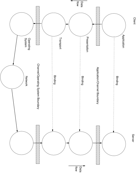
The prescriptive model, [ODP95], generalizes the concept of connection between client and server to be a logical binding which is realized by both client and server using a channel, see also [Otw95]. Figure 1 illustrates the concepts of bindings and channels. Application objects have bound with one another probably using a naming service; they have negotiated a channel configuration that requires two objects: a data presentation conversion object and a data transport object. The channel configuration is fixed by bindings. The client sends data; the server receives. The data is passed from the application object to the channel which carries out the conversion and the transport to the server.
- Binding
-
A binding is a contract between the client and the server stating the parameters by which they will communicate. A binding between two transport objects would usually specify:
-
•
Transport layer protocol to be used, e.g. UDP/IP or TCP/IP or Pipe/Unix.
-
•
Transport layer parameters
-
•
Network addresses for chosen transport layer protocol
The presentation layer object would convert from the the local data representation to a network representation. The only specification needed here is the source and target representations. In this case, the binding is implicit in the implementation of the objects, they need not be initialized with parameters.
More sophisticated systems will have higher demands and will insist that other services be used as well, for example:
-
•
Data security
-
•
Transaction management
-
•
Call billing
-
•
Data compression
-
•
Relocation manager
These would all require that configuration parameters be specified and may also demand that they are operate together.
-
•
There is no need for channels to be symmetric, the server could implement a call–logging object in its channel without having an object of the same type in the client’s channel.
Bindings do need to be current. A transport object might close a connection, in which case, it would no longer be current, but if it were to leave enough information to allow a re–connection, then it is, in effect, still current.
Tri–partite Bindings
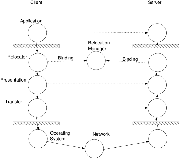
Bindings need not be bi–partite. An application service that would require a tri–partite binding is relocation management, illustrated in figure 2. The idea of which is that should the server choose to relocate, it would notify a relocation manager of its new addresses and move there. When the client calls the server at its old address and fails to reach it, the relocator object in the client’s channel would call the third party and ask for the new address of the server, establish a new set of bindings with it, i.e. construct a new channel and destroy the old, and send the message again. This would all be transparent to the application object.
The relocation object in the channel would need to call the relocation manager for the new addresses and would thus become an application object; it would need to establish its own channel with the relocation manager.
1.2 Inflexible System Designs
Although the ISO–ODP defines a flexible architecture, most implementors of distributed processing platforms provide application programmers with inflexible systems: the channel can only contain a presentation and a transport object.
Presentation: Stubs and Skeletons
Both CORBA ORBs and the RMI defined in Java make use of “stubs” and “skeletons” and a stub–compiler. The term infrastructure will be used for the engineering that realizes an ORB or RMI.
- Stubs
-
These are used by a client when invoking a method on a remote server. The client does not have a local implementation for the service the remote server has, but it will have a definition of its interface which can be used as if it were the implementation of the service. It can present the interface definition to a stub–compiler which will generate code to invoke each method on the remote server. The stub acts as a proxy for the remote server in the client’s address space. The stub for each method needs to do the following things:
-
1.
Construct a request
A request object is a container entity that carries the invocation to the server; it contains:
-
•
The address of the remote server
-
•
The name of the method being invoked, possibly with version control information for the interface.
-
•
The parameters for the method
-
•
The return address
The stubs can also contain the code to marshall111The verb is to marshal, but this is so often mis-spelt that to marshall has become acceptable. the parameters into a universal transfer presentation. In this form, the stubs also comprise the presentation object.
-
•
-
2.
Invoke the request
The request, now just a sequence of bytes with an associated address for the server and a return address for the sender, is passed to the infrastructrure which sends it to the network socket for the server.
-
3.
Get the reply
The server will return a reply in another container type.
-
4.
Re–construct the reply
The reply is then re–constructed or, rather, its contents are un–marshalled and returned to the client. Again, this may be part of the code in the stubs.
-
1.
- Infrastructure
-
It might be best now to explain how the infrastructure manages to provide the RPC service.
-
1.
At the server on creation
An application programmer defines an interface and produces an implementation for it. A program that effectively acts as a loader issues instructions to the infrastructure to create a socket to receive requests for that server and will associate the remote server implementation with that socket.
-
2.
At the naming service
The application programmer will ensure that the address of his newly–created remote server is put into a well–known naming service. The client will then collect the address from the naming service.
-
3.
At the client on invocation
The address collected at the naming service will contain enough information to allow the client’s infrastructure to send the request container as a stream of bytes to the socket that the server’s infrastructure has associated with the remote server’s implementation.
-
4.
At the server on invocation
The network socket will be activated by the client’s infrastructure (a connect and a data send) and the server’s infrastructure will collect the data at the socket and, because it has recorded the object responsible for that socket, it can activate the server skeleton.
-
1.
- Skeletons
-
These are invoked by the server’s infrastructure when the network socket for a server is activated and the data comprising a call has been collected. It invokes the implementation of the method the client wants to use at the server. A skeleton can consist of one method that unmarshalls enough of the request container to be able to look up the method to invoke—this is known as dispatching.
This partial unmarshalling has to be done in this way, because each method will unmarshall the remainder of the request container differently to obtain the parameters to pass to the server’s method implementation.
After the invocation is made the results will be marshalled into a reply container which is then sent back to the client.
The stubs and the skeleton effectively form the presentation channel object. Stubs have to be produced by a stub–compiler, but skeletons can be made generic, if the underlying infrastructure supports a reflective invocation mechanism, see java.lang.reflect or the CORBA Dynamic Invocation Interface.
Some stubs generated by the Java rmic, Remote Method Interface Compiler, are given in appendix A. These demonstrate the use of reflective language features.
Transport
When the request containers are passed to the infrastructure the transport object is eventually invoked. Most ORBs only provide one transport mechanism which sends data through TCP/IP sockets to its destination. Although some systems do allow different protocols: UDP/IP or Pipe/Unix.
Limitations
The problem with this is that if one wants to implement any useful application services—encryption, billing and so forth—the infrastructure does not help. For example, to encrypt and decrypt data sent as part of a remote procedure call, one would have to implement one’s own stubs and skeletons, see figure 3.
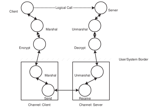
The application programmer has to construct a call, marshall the data, encrypt it, send it using a generic method, which will marshall it again. At the server, the data would be delivered to the generic method, and the application programmer would then have to decrypt it, unmarshall the decrypted data, reconstruct the call and dispatch it. After dispatching, collect the results, marshall, encrypt and return the reply.
1.3 More flexible: Java RMI Custom Socket Factories
A more flexible implementation has been provided by Sun in Java . It allows a different type of socket to be used as the transport object.
Method
The custom socket factories have to implemented in the following way:
-
1.
Derive and implement classes for the new socket type’s datastream from java.io.FilterOutputStream and java.io.FilterInputStream, call them MyOutputStream and MyInputStream.
-
2.
Derive and implement classes for the new socket types java.net.Socket and java.net.ServerSocket that use the new streams MyOutputStream and MyInputStream.
Then create socket factory implementations that can be used by RMI.
-
1.
A client-side socket factory that implements RMIClientSocketFactory and implement the RMIClientSocketFactory.createSocket() method.
-
2.
A server-side socket factory that implements RMIServerSocketFactory and implement the RMIServerSocketFactory.createServerSocket() method.
Then one has to ensure that the constructor for the remote server is told to use the new socket factories. The infrastructure creates the new type of socket when demanded and invokes the create socket methods.
The RMISecurityManager at the client will then determine that a particular type of socket has to be used and will load the custom socket factory implementations.
Possibilities: Implementing SSL
Using custom socket factories, it is possible to implement a Secure Socket Layer. The RMIClientSocketFactory.createSocket() would be used to perform the key exchange with the server and the custom input and output streams would apply the session key to encrypt on send and decrypt on receive.
Limitations
Unfortunately, using custom socket factories only increases the variety of the transport objects that can be employed, it does not allow different kinds of objects to be placed in the channel.
2 Channel Objects
What is needed is a means of placing objects in the channel before and after the presentation object. These objects should have a simpler instantiation and invocation procedure than using the custom socket method in Java .
2.1 Some Requirements
-
1.
Different interests System Configurable
The objects placed in the channel between client and server are the result of a negotiated agreement between the client, its server and their respective environments. It is well–known that security requirements for messages depend on the workstation that the client is using [Ash99], which may be connected to a secure local area network on which both the the client and server reside and so, for example, no security measures need be taken; or, the client could be accessing the server remotely from the Internet through a modem in which the server might require that the client use encryption.
It would be desirable if the client and the server could both specify their requirements and some negotiation take place that could create a mutually acceptable protocol stack in the software communications channel.
-
2.
Different Methods for Different Actions
A request and reply actually require that four different channels be traversed by messages, see figure 4:
-
(a)
Request this channel is created by the infrastructure for the client and sends a message over the network.
-
(b)
Indication this channel is used to receive from the network and is created by the infrastructure for the server.
-
(c)
Response created by the infrastructure for the server to return the results of the client’s request message.
-
(d)
Confirmation receives from the network and is created by the infrastructure for the client.
Should an error occur at the server it is returned via the response and confirmation messages.
The stubs are responsible for managing the thread of execution of the application object: once a message is put onto the request channel, the application object’s thread can be suspended whilst it waits for the reply to arrive on the confirmation confirmation channel.
If the message is a cast of some kind (broadcast, multi–cast or one–cast) there will be no response or confirmation.
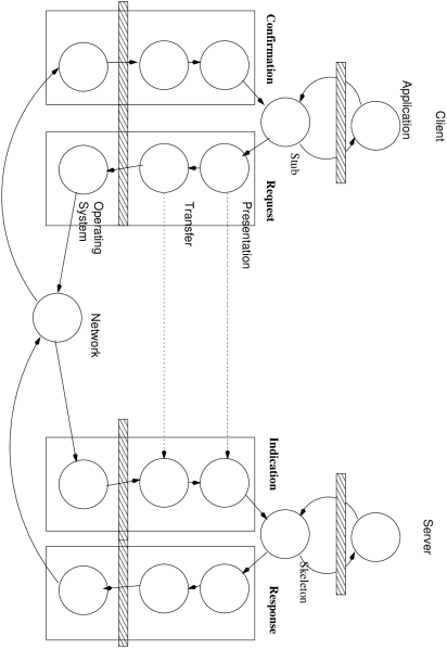
Figure 4: Four channels are used in a request and response -
(a)
-
3.
Different Implementations
Most channel objects are derived from the same source and will have the same implementation. Java allows classes implementing different objects to be loaded over the network, so it would be possible for the client and server to agree upon and load the same class implementation, which they would be able to do with the custom socket factories method. This may not always be the case, some channel objects may be optimized to make use of a different operating system, but provide the same functionality. Audio and video data streaming are good examples of this need: some micro–processors now have support for stream data.
-
4.
Transparency
-
(a)
Management
It would be desirable if the additional services provided by the channel objects did not need to be initialized or managed by either the client or the server application programs but they were activated by their respective infrastructures.
-
(b)
Exception handling
One of the difficulties of developing applications in enterprise environments is that as messaging becomes more sophisticated—supporting for example, confidentiality, authorization, call–billing—the number of possible errors increases because each of these sub–systems introduces new ones. It must be possible for channel objects to clear down their own errors, so that errors returned to application objects only involve the application.
-
(c)
Using Possession rather than Inheritance for Coupling
It would also be desirable if the classes for the channel objects did not extend the existing class hierachies of the message transmission sub–system, in the way that custom socket and socket factories do. Extending class hierachies is not as flexible as specifying an order of invocation.
-
(d)
Interface Definitions Suitable for Reflection.
It would also be desirable if the infrastructures could load channel objects’ classes remotely and have a simple enough invocation syntax so that reflection mechanisms could be used to invoke the channel objects without requiring a stub compiler. Java already does this with its version 1.2 stubs, using package java.lang.reflect, and CORBA has a Dynamic Invocation Interface which can achieve the same goal.
-
(a)
-
5.
Efficiency
It would also be desirable if the channel objects did not create a large stack of calls; primarily because some target environments for remote procedure call platforms will be embedded systems on SmartCards [SMT99].
2.2 Some Nomenclature
With the aid of figure 4, it is possible to be more precise with the terms used:
-
•
Initiator: starts a four–phase call sequence; may also be called the requestor.
-
•
Acceptor: accepts the call made upon it; may also be called the responder, because it generates the response.
Both an initiator and an acceptor will send and receive as part of four–phase call sequence. Ordinarily, the client will be the initiator of all calls, but some remote procedure call systems permit call–backs, in which case the server is the initiator and the client the acceptor.
3 Architectures for Channel Objects
There are basically two types of architecture that could support channel objects.
3.1 Stream–oriented Architecture
The custom socket factory architecture is stream–oriented. It acts upon the data being sent between client and server as a stream applying a data transformation to the data when it is sent and undoing this transformation at the other end.
The data is treated as opaque and can be delivered in packets as small as one byte. The implementor of the stream handler does not know whether the data has just started or is about to finish.
One of the attractions of this approach is that many of the operations that data networks perform on data can be implemented in software: segmenting, and its converse re–assembling, can be implemented easily and this would allow remote procedure call systems to make use of packet–oriented transmission, such as UDP/IP. Segmenting and re–assembly could be implemented as channel objects and data would be segmented and then sent as packets on a UDP socket for re–assembly by another channel object at the server.
Streams can be chained—the output of one providing the input for the next. Most operating systems support pipes to do this: Java supports the java.io.PipedInputStream, and output, classes.
Multi–casting could be easily achieved with pipes: simply have a pipe that sends on a socket and echoes its input; then connect a series of these together.
A stream–oriented architecture is better for real–time data delivery. All of the processing in the stream–handler is applied to the data—it is not expected to communicate with relocation or transaction managers and incur indeterminate time penalties. Consequently, the emphasis in the design of stream–handlers should be to ensure they introduce a constant latency in transmission and reception.
3.2 Call–oriented Architecture
This architecture implicitly appreciates that the data being delivered is a call.
Call–handlers usually add parameters to a remote procedure call. They do not form part of the message sent by the application object, but set its context. For example:
-
•
Timestamps logging when messages are sent and received by adding an “time–sent” parameter to the remote procedure call.
-
•
Accounting adding an account identifier to a remote procedure call so that the server can log charges for calls to a particular account.
-
•
Transactions a transaction might consist of a number of calls to different servers, they could all be identified with a transaction identifier, to synchronize committing and aborting transactions as a whole.
-
•
Authorization a Privilege Certificate could be attached to the call so that the server could check what rights and privileges the caller is allowed to exercise within the server’s work–space.
A call–oriented architecture should be implemented so that it has access to the parameters passed as part of the request. If this is the case, then as well as being able to add parameters, it would be possible to perform data transformations on parameter values that are part of the call. For example:
-
1.
Representation conversions
-
(a)
Wholly
The presentation objects implemented in remote procedure call systems change the data representation of the parameters of a call so that they can be transmitted over the network as a sequence of bytes, with the receiver being responsible for converting the byte–sequence to its local representation. It may be more efficient to convert to the receiver’s format before the data is sent so that the server can use conversion methods available from its native operating system.
-
(b)
Partly
It might be the case that a server has a different data context for a particular data type: internationalization of text strings and currency formats could be converted prior to transmission.
-
(a)
-
2.
Pseudo–Objects
Pseudo–objects are usually legacy systems that can be directly controlled by the client’s remote procedure call infrastructure, but for the sake of uniformity, and to simplify re–engineering and relocation of services, they are provided with the same interface as remote servers. The operating system used by a distributed processing platform is itself a legacy system.
An example of a pseudo–object that application programmers use is the database driver provided in the Java DataBase Connectivity package, java.sql. This pseudo–object implementation establishes and drives a connection with the database. Other examples of services that could be implemented as pseudo–objects are directory and naming services that are available through native operating systems.
-
3.
Stream
A call–oriented architecture could also be used to transform data in the same way that a stream–oriented architecture could. Encryption, compression and checksum insertion could all be performed by marshalling the parameters using a data representation object to produce a sequence of bytes and then applying the stream operation to it. The output would be opaque and would replace the parameters.
A call–oriented architecture is better suited to recovering from errors, since it is possible to determine which channel object is at fault and it can take measures to recover from the error.
3.3 Both architectures are needed
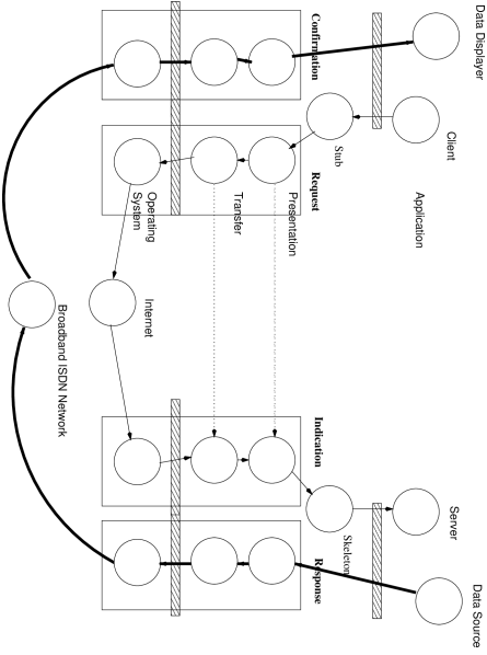
The stream–oriented architecture is ideal for delivering data at high speed with a determinate latency, the call–oriented architecture is ideal for communicating control information. This is a similar design problem that faced the developers of telephone networks and it was resolved, in the Integrated Services Digital Network, ISDN [IEE90], by having a control channel manage the use of two bearer channels. Figure 5 illustrates a request made to the server on a control channel and a reply being received on a broadband data channel. This sort of architecture could be used for controlling the delivery of “pay–per–view” television, where the RPC mechanism is used by an application to make a payment over a control network and the data is delivered on differently constructed channels over a broadband network possibly to different hardware.
Essentially the differences between the two architectures, with regard to the activation of the channel objects, are:
-
•
synchronizing with the call, and
-
•
the opacity of the call’s contents
A stream–oriented architecture need not transmit data to the server in a contiguous block that represents the marshalled bytes of a message. A call–oriented architecture would have each channel object invoked with each call sent.
A stream–oriented architecture only has access to the marshalled bytes that represent a message. A call–oriented structure sees the method that is invoked and the parameters for it.
The most flexible architecture is the call–oriented one. But for implementing the transport objects, a stream–oriented architecture should be preferred. This means that the two architectures fall above and below the marshalling channel object, see figure 6.
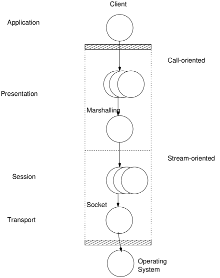
This figure attempts to place the channel objects in an Open Systems Interconnection model, [ITU94]. Objects in the call–oriented architecture provide presentation layer services and, after the marshalling object, which reduces a call to a sequence of bytes, the session objects and finally the network transport object, a socket driver, can operate upon the data as a stream. The session layer objects would also perform stream–oriented encryption, but a presentation layer object would negotiate keys.
Channel objects that are call–oriented will be called call–handlers and those that are stream–oriented will be called stream–handlers.
The marshalling object is a call–handler and, if need be, it could invoked a number of time to render the data as a sequence of bytes. This would be useful for data security, since it may be necessary to encrypt the data and make it unintelligible to other call–handlers.
4 Stream–Oriented Architecture: Design
Sun with Java and the socket factory technique have implemented what is described later as a simplex system, §5.2 : each stream has two channel objects, one for sending—the output stream—and one for receiving—the input stream. There are two kinds of pairs: the client’s, or, more precisely, the initiator’s, pair and the server’s, or acceptor’s, pair.
Although there is no explicit code to synchronize the two streams so that only one may be used at a time, it is not expected that an application can simultaneously send and receive. This limitation could be removed by a suitably designed channel object which could specify a different return address.
5 Call–Oriented Architecture: Design
As pointed out above, a message passed between a sender and receiver would negotiate four different channels:
-
1.
Request
-
2.
Indication
-
3.
Response
-
4.
Confirmation
but if the call is a cast of some kind, it need only have two:
-
1.
Request
-
2.
Indication
And some parts may not do anything, for example a request handler could log all calls made by the client, but the server need not record all the calls that are made upon it.
When an application programmer makes use of a remote procedure call the infrastructure sends the message to the server and blocks the thread pending the arrival of the confirmation. One could also implement the channel objects in this way. This leads to two different architectures:
-
•
Either: one channel object for each of request, indication, response and confirmation Simplex.
-
•
Or: two channel objects: one that requests and blocks pending the arrival of a confirmation; one that receives indications, invokes the service (and blocks waiting for it) and then sends the response Duplex.
The latter will be discussed first.
5.1 Duplex: One Pair of Objects
One channel object for the initiator performs request and confirmation, another channel object performs indication and response for the acceptor. This means that every channel object has a bi–directional data–flow with the channel object below it, rather like the application object has with the distinct channels in figure 4. This has the attraction that should the initiator’s channel objects for the request and the confirmation need to share state, then this is achieved implicitly because they are the same object.
This has a problem with broadcasts, (or one–casts). The initiator’s channel object (request and confirmation) needs to determine if it is to block or not and that would require this information be made available to the channel object, perhaps best supplied as a parameter to the method invocation. This information is required in CORBA, the Interface Definition Language allows methods on interfaces to be marked as one way, but is not part of the Java specification; although it could be inferred if the definition of the remote method returns no result, in which case, the method can be invoked as a one–cast. However, if exceptions are returned by the remote server then the method is a call: the exception, whether raised or not, is a response.
5.2 Simplex: Two Pairs of Objects
If a channel object is implemented for each stage of the communication, then there are, at most, two pairs of objects: a request and confirmation pair at the initiator; an indication and response pair at the acceptor. Figure 4 illustrates the engineering of this.
Because the objects are distinct they will need to bind with one another should they need to share state: an example of the difficulties this might lead to can be seen when communicating and attempting to correct errors.
The infrastructure would block the application programmer’s thread of control pending the arrival of the confirmation message from the server containing the results of the call. Ordinarily, the confirmation channel objects will unravel the message returned by the server, instantiate the result for the application programmer’s thread and unblock it.
If there is an error in any of the channel objects, then it should be possible for the channel objects to attempt to clear the error and resend the message if need be. The problem then is that the channel objects in the request channel need to be synchronized with the error results received in the confirmation channel. If there is a failure in one of the channel objects in the indication channel, then they must be propagated via the response and confirmation channels. This is a difficult issue and is discussed later at greater length, §6.4 .
The important difference between the duplex and simplex methods is the relationship to the state of the call. With the duplex model the request channel retains the state of the call awaiting an acknowledgement from the confirmation channel. What makes the duplex model retain state is that the channel objects invoke one another and form a stack of calls which can be associated with a thread.
This can be emulated in the engineering of a simplex model without requiring the use of the stack, by passing a call identifier. This would only be of use if the channel objects were also to retain their internal state when they release control.
Example: A Secured Message Delivery Service
As an example, an encryption and decryption service would require:
-
1.
Request encrypt
-
2.
Indication decrypt
-
3.
Response encrypt
-
4.
Confirmation decrypt
There are only two functions—encrypt and decrypt—but performed at four locations. It should be possible to provide just one pair of implementations—an Encryptor and a Decryptor—located differently.
-
1.
Encryptor
-
•
Request channel object initiator
-
•
Response channel object acceptor
-
•
-
2.
Decryptor
-
•
Indication channel object acceptor
-
•
Confirmation channel object initiator
-
•
Encryptor and Decryptor would both be implemented as stream–handler channel objects.
Encryption is subject to replays of old messages unless the messages are time–stamped and sequenced. Usually, time–stamping and sequencing are implemented as part of the encryption and decryption objects, but with channel objects they can be provided separately. Time–stamping has two functions:
-
1.
Request timestamp issue
-
2.
Indication timestamp check
-
3.
Response timestamp issue
-
4.
Confirmation timestamp check
Two functions: StampIssuer, StampChecker; four locations:
-
1.
StampIssuer
-
•
Request channel object initiator
-
•
Response channel object acceptor
-
•
-
2.
StampChecker
-
•
Indication channel object acceptor
-
•
Confirmation channel object initiator
-
•
Similarly for a sequence number generator and checker.
StampIssuer and StampChecker would both be implemented as call–handler channel objects.
Because it is difficult to synchronize clocks in a distributed networks, some secure message delivery systems allow some skew on the clocks and use checksums to detect replayed messages. Only the acceptor’s indication channel and the initiator’s confirmation need deploy a ReplayDetector object. It would be implemented as a call–handler generating a checksum from the marshalled data incoming as an indication or as a confirmation.
5.3 Simplex or Duplex
There is a greater similarity in the simplex architecture to the engineering underlying the messaging system than in the duplex architecture, but the duplex architecture has some attractive state–retention properties which should be emulated in a simplex architectureq. The rest of this discussion will concern itself with a simplex architecture that attempts to retain state across all four phases of a call.
The other great attraction of the simplex architecture is that if the channel objects reside in different channels, then it is easier to relocate the channel. This would be especially useful when a call uses two different media as the example system in figure 5 illustrated.
6 Service Invocation Semantics
From what has been said above, the Java RPC mechanism has a stream–oriented architecture and what follows is a proposed call–oriented architecture for it. It should serve as an example of how channel objects could be deployed in other CORBA RPC systems.
The distributed processing infrastructure will have to determine the order in which the channel objects will be invoked. There are now two ways in which the methods of the channel objects can be invoked and how they should bind with one another.
-
•
Either: have the request object invoke a method on the indication object and block waiting for the response: Peer–to–Peer invocation.
-
•
Or: have the request object perform its work and return a modified call object and return immediately: Service invocation.
The peer–to–peer option requires the duplex architecture which has been dismissed, so only the service method of invocation is left. Peer–to–peer is very attractive, it would allow channel objects to be client–server pairs and thus be able to use the stub–compiler. Unfortunately, it would demand too much memory to stack all of the calls required to navigate complicated protocol stacks.
The approach taken by Sun in their own implementation of java.rmi.server.RemoteRef, shipped as sun.rmi.server.UnicastRef as part of the Java Runtime Environment, is suitable for the simplex architecture proposed. Referring to the the code fragment given in the appendix §A.2 , the key method is java.rmi.server.RemoteRef.invoke(). It is implemented along the lines given in the next code fragment: note the two comments indicating when the two types of channel objects should be invoked.
package sun.rmi.server;

public class UnicastRef implements RemoteRef {

  public Object invoke(Remote r, reflect.Method m,
                       Object[] p, long l) throws Exception
    {
      // *Request channel objects should be invoked now*

      // Establish a connection using information in Remote r

      // Get the streams associated with the connection
      // Marshall data onto the stream
      // Execute the call

      // *Confirmation channel objects should be invoked now*

      // Unmarshall
      // Release the connection
      // Return the result
    }
}
6.1 Wrappers: Request and Response Channels
The channel objects would be invoked serially and would be passed the same parameters as invoke(), collectively call these a Message object. The request channel objects would return a Message object, but these would usually have the original message as one of its parameters. This is a simple encapsulation procedure and is illustrated in figure 7, where a time–stamping channel object has been passed the application object’s message. The application object wants to invoke method query(), the channel object passes this message as a parameter of its own message. That message invokes method stampedAt(). The two message objects might duplicate target and return addresses, it should be possible to remove this redundancy, but it should still be possible to specify a different target address and a different return address if need be.

6.2 Unwrappers: Indication and Confirmation Channels
The objects located in the indication and confirmation channels would need a skeleton rather like that described above, §1.2 , either a dispatcher or use a reflective invocation on the channel object’s service implementation. After the service has completed processing, it would return its results to the skeleton which would then return the message object to the infrastructure.
6.3 Counterparts and Associates
Some channel objects will have counterparts in the remote channel, for example, a time–stamping request channel object should have a time–stamp checking indication channel object, but some may not, for example a request logging channel object placed in a server’s indication channel. If a channel object sends then its counterpart receives and vice–versa.
A channel object can have an associate in a local channel. A request channel object could have an associate in the confirmation channel. If a channel objects sends then its associate receives and vice–versa.
Figure 8 should help to clarify this.
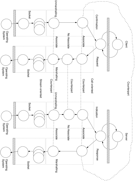
-
1.
Marshalling and Unmarshalling
Looking at the marshalling and unmarshalling objects: the marshalling object in the client’s request channel has a counterpart in the server’s indication channel and an associate in the client’s confirmation channel.
-
2.
Timing
The top layer of channel objects are used for timing: time–stamping and time–checking, they comprise a full complement, where each channel object has an associate and a complement.
-
3.
Usage
The second layer of channel objects is used to record usage statistics and only logs requests and responses, so they have no associates but a counterpart.
Clearly, this might prove to be cumbersome, it might be simpler to insist that all channel objects have a counterpart and an associate and have a default implementation which just copies the message over.
6.4 Exception Handling
Any of the channel objects can raise an exception, but part of the function of channel objects is to attempt to clear exceptions, for example:
-
•
relocation objects would obtain new addresses for servers,
-
•
key management objects would obtain new keys in the event of expiry.
-
•
authorization managers could obtain new privileges.
The channel objects have to retain some state that would allow them to act upon exceptions. This would require that they place state in a common object that associated channel objects can access. The state would need to be stored with an identifier unique to the call.
-
1.
Exception Handling in One Channel
-
(a)
Clear
When one channel object raises an exception, the infrastructure signals the other channel objects in the same channel, in the reverse order in which they were invoked, asking them to attempt to clear the exception.
-
(b)
Uncleared: Undo
If the exception cannot be cleared then the channel objects should be signalled to undo their previous actions.
-
(c)
Cleared: Undo and Redo
If the exception can be cleared then the channel objects may need to undo their previous actions and be allowed to redo them.
Redo is a distinct operation, because it may allow the implementation to be optimized for error recovery.
Co–ordinating this is a little difficult. There are two sequences:
-
(a)
Attempt to clear then undo and then redo
Each object in turn in ascending order (i.e. reverse order to invocation) attempts to clear the exception, if any one succeeds then the undo operation is invoked in ascending order to the top of the channel. Then the redo operation is invoked in descending order.
-
(b)
Attempt to clear and undo and then redo
Each object in turn in ascending order (i.e. reverse order to invocation) attempts to clear the exception and performs an undo. If any one succeeds then the undo is invoked on the remaining objects in ascending order and then the redo operation is invoked in descending order.
The former might prove more efficient if errors are expected to be cleared, the latter if not. The idea is communicated in figure 9, but the details of invocation are not.
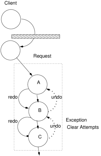
Figure 9: Exception handling in one channel If the latter scheme (Attempt to Clear and Undo Simultaneously) is used: channel object raises an exception, it undoes its action, passes back the original message it received to object which also undoes its action and returns the original message it received to . clears the exception and redoes its action and passes the message on to which also redoes its action and thence to .
-
(a)
-
2.
Exception Handling Across Channels
If a receiving counterpart raises an exception, it should be signalled to the sender: this would be achieved by the receiving counterpart sending a message to its sending associate to raise an exception with its receiving counterpart. Java already has a proven mechanism for this, objects of class Exception can be contained in objects of class RemoteException.
-
(a)
Exception raised in the Indication Channel
As an example, see figure 10, a request channel object sends a message which raises an exception in the indication channel, the channel object in the indication channel raises an alert with its associate in the response channel, which sends an exception to its counterpart in the confirmation channel.
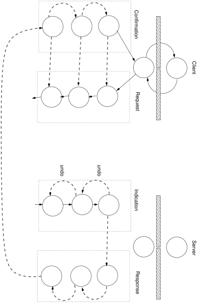
Figure 10: Exception handling across channels Points to note in figure 10 are:
-
i.
The indication channel is cleared down
-
ii.
The server receives no message
-
iii.
The response channel propagates the exception
-
iv.
The objects in the confirmation channel can signal their associates in the request channel.
It might be possible for the request channel objects to invoke the same procedure as portrayed in figure 9, clear the exception and re–send the message, this would require that they have access to the message as issued by the client.
-
i.
-
(b)
Exception raised in the Confirmation Channel
If a response channel object sends a message which raises an exception in the confirmation channel, then the confirmation channel object would signal its associate in the request channel, which may, if it has retained state, i.e. the message it sent, be able to clear the exception and re–send without intervention by the client application object.
-
(a)
6.5 Interfaces and Classes
6.5.1 A Message Class
A simple message class is needed to contain the parameters passed to the invoke() method and to all the channel objects.
package java.lang.rmi.channel;

import java.rmi.*;
import java.lang.reflect.*;

public class Message {
  Remote remote;
  Method method;
  Object[] parms;
  long hash;

  public Message(Remote r, Method m, Object[] p, long h) {
    remote = r;
    method = m;
    parms = p;
    hash = h;
  }
}
6.5.2 Channel Objects
Basic Interface
Channel objects then all have the same interface and it is their location which determines their function, i.e. whether they wrap or unwrap.
package java.lang.rmi.channel;

public interface Handler {
  public Message clear(Message m, Exception e) throws Exception;
  public Message todo(Message m) throws Exception;
  public Message undo(Message m, Exception e) throws ClearedException;
  public Message redo(Message m) throws Exception;
}
Both methods of clearing exceptions are covered in this interface because there is a separate clear() method.
Exceptions
The undo() method throws an exception to indicate it has cleared the exception it was passed.
package java.lang.rmi.channel;

public class ClearedException extends Exception {

    public ClearedException(String s) {
      super(s);
    }

    public ClearedException(String s, Exception ex) {
      super(s, ex);
    }

}
Other exceptions which might make processing more decisive:
-
1.
Unclearable
It might also prove useful to have clear() raise an exception that the exception cannot be cleared and this would allow the infrastructure to request a re–send decision from the application object.
-
2.
Rebind
It might also prove useful if the channel objects can demand a rebind and force the destruction of their channel. This would be useful for a relocation channel object.
Handler Specification
The next is an abstract class that provides a container to hold the channel objects which would be loaded by the infrastructue. It might be wise, for security reasons, to implement the class more fully and make the getHandler() method final. The class also provides a means of obtaining associates and counterparts.
package java.lang.rmi.channel;

import java.rmi.*;

public abstract class Handlers
{
  public static final int REQUEST = 1;
  public static final int INDICATION = 2;
  public static final int RESPONSE = 3;
  public static final int CONFIRMATION = 4;

  public Handlers() {
    ;
  }

  Handler getHandler(int identity) {
    return null;
  }

  Remote getCounterPart(int identity) {
    return null;
  }

  Object getAssociate(int identity) {
    return null;
  }
}
Channels
Channels themselves would be simple containers probably implemented with a vector object which can be easily iterated in the invoke() operation.
package java.lang.rmi.channel;

import java.rmi.*;

public abstract class Channel
{
  private int identity = -1;
  private Handlers handlers;

  public Channel(int id, Channels h) {
    identity = id;
    handlers = h;
  }
}
6.5.3 Channel Objects: Binding and Invoking Methods
Binding
Channel objects would need to bind with one another, so that they can exchange parameters. The channel object methods are defined on one interface, they can therefore suppport other methods on another service interface.
Invocation
When a channel object is passed a message object, it will need to invoke a method on its counterpart. The easiest way for it to do this is to use the same stub and skeleton mechanism for dispatching a call as remote procedure calls use. As can be seen in figure 7, where one channel object adds enough parameters to the message so that when it is received by its counterpart, it can use a local invoke() method to pass the parameters and obtain the resulting message object from a local service interface.
If channel objects have to invoke methods upon one another they can either send them with the message or they can go “out–of–band” and communicate them directly if they support the java.rmi.Remote interface using their own channel.
7 Summary
7.1 Previous Work
Java certainly has the functionality to implement channel objects. The author has already implemented a similar scheme (using a duplex, peer–to–peer architecture) for a variant of the ANSAware, [APM98], known as DAIS, the distributed processing platform produced by ICL, [ICL98], which was CORBA compliant. That implementation, written wholly in C, [KR78], was able to support a Kerberos, [NT94], authentication and confidentiality service invisibly to the application programmer, the channels were constructed according to a template specified by an environment variable.
The author has developed a prototype application which can support the Transport Level Security protocol. (A fairly rigorous treatment of both it and the Kerberos protocol is given in [Eav99].) A simple channel object is put in place that negotiates the keys, whilst a custom socket is used to perform the encryption.
ANSAWare evolved to a product known as Reflective Java, [WS97], which supported channel objects, but was designed to provide support to application objects—presentation of data and so forth—and not to provide system services.
7.2 Difficulties of Binding
The principal difficulty faced in these prototypes is that there is no simple or well–defined mechanism for expressing how two parties should bind with one another. ANSAware had a well–developed binding model, [Otw95], but its final implementation had a limited number of quality of service parameters.
Java now has a very well–developed security architecture, [SUN98b], but currently seems to have no means of specifying the degree of security required, it seems to be principally oriented towards setting permissions. (Of course, a permission one does not have is a requirement.) The SecurityManager would appear to be the best–placed component of the Java security architecture to negotiate and configure channels. It will be difficult for any distributed processing platform to achieve any degreee of acceptance in an enterprise–wide data processing environment if it is not possible to implement many of the logging services that have long been available in mainframe systems. The most pertinent example of which is CICS [Wip87], the Customer Information Control System, which was originally a messaging system, but was extended to become a transaction monitor that could manage database enquiries.
Hopefully, with channel objects in place, remote procedure calls could do the same across the World–Wide Web.
Appendix A Stubs for the RMI of Java
The Remote Method Invocation package of Java needs to use a stub–compiler to generate stubs. It no longer needs to generate skeletons for servers.
There is, of course, no need to distribute the stubs, the client can collect them from the server.
A.1 Interface and Implementation
Interface
This very simply returns a string, given a string.
package rmi.demo;

public interface Answerer extends java.rmi.Remote {
  String answer(String mesg) throws java.rmi.RemoteException;
}
Implementation
This is the implementation of the interface. Most of the code involves posting the server’s reference to the Naming service.
package rmi.demo;

import java.rmi.*;
import java.rmi.server.UnicastRemoteObject;

public class AnswererImpl
  extends UnicastRemoteObject
  implements Answerer
{
  private String name;

  public AnswererImpl(String s) throws RemoteException {
    super();
    name = s;
  }

  // Begin
  // Remotely accessible methods
  // Parameters have to be implementations of Serializable

  public String answer(String message) throws RemoteException {
    System.out.println("Received:" + message);
    return new String("You said:" + message);
  }

  // End

  public static void main(String args[])
  {
    // Create and install a security manager
    System.setSecurityManager(new RMISecurityManager());
    // Without it no new classes can be loaded

    try {
      System.out.println("Construct");
      AnswererImpl obj = new AnswererImpl("AnswererServer");
      System.out.println("Bind");
      Naming.rebind("AnswererServer", obj);
      System.out.println("Bound");
    } catch (Exception e) {
      System.out.println("AnswererImpl err: " + e.getMessage());
      e.printStackTrace();
    }
  }
}
A.2 Stub
This is the version 1.2 stub for the rmi.demo.Answerer service interface.
-
1.
Reflective Language Features
The most important feature of these stubs is that they make use of the capabilities provided by java.lang.reflect. When the class is loaded by the client, and it is designed to be loaded from a remote location, the initialization code instantiates the java.lang.reflect.method attribute for the stub $ method_answer_0 using the getMethod() method of java.lang.Class.
-
2.
Instantiating objects that implement rmi.demo.Answerer
Because the client has to use the naming service to locate an object that implements the rmi.demo.Answerer, the naming service loads the stub class and calls the constructor in it rmi.demo.AnswererImpl_Stub(). The client casts the object the naming service returns to be rmi.demo.Answerer.
-
3.
Invoking methods
The stub compiler generates proxy implementations of the methods that are declared in rmi.demo.Answerer. They use the reflective method variable $method_answer_0 and the java.rmi.server.RemoteRef.invoke() method.
// Stub class generated by rmic, do not edit.
// Contents subject to change without notice.

package rmi.demo;

public final class AnswererImpl_Stub
  extends java.rmi.server.RemoteStub
  implements rmi.demo.Answerer, java.rmi.Remote
{
  private static final long serialVersionUID = 2;

  private static java.lang.reflect.Method $method_answer_0;

  static {
    try {
      $method_answer_0 =
        rmi.demo.Answerer.class.getMethod("answer",
                                          new java.lang.Class[]
                                          {java.lang.String.class});
    } catch (java.lang.NoSuchMethodException e) {
      throw new
        java.lang.NoSuchMethodError("stub class initialization failed");
    }
  }

  // constructors
  public AnswererImpl_Stub(java.rmi.server.RemoteRef ref) {
    super(ref);
  }

  // methods from remote interfaces

  // implementation of answer(String)
  public java.lang.String answer(java.lang.String $param_String_1)
    throws java.rmi.RemoteException
    {
      try {
        Object $result =
          ref.invoke(this, $method_answer_0,
                     new java.lang.Object[] {$param_String_1},
                     -8351992698817289230L);
        return ((java.lang.String) $result);
      } catch (java.lang.RuntimeException e) {
        throw e;
      } catch (java.rmi.RemoteException e) {
        throw e;
      } catch (java.lang.Exception e) {
        throw new
          java.rmi.UnexpectedException("undeclared checked exception",
                                       e);
      }
    }
}
Appendix B Funding and Author Details
Research was funded by the Engineering and Physical Sciences Research Council of the United Kingdom. Thanks to Malcolm Clarke, Russell–Wynn Jones and Robert Thurlby.
Walter Eaves
Department of Electrical Engineering,
Brunel University
Uxbridge,
Middlesex UB8 3PH,
United Kingdom
References
- [APM98] ANSA consortium. World-Wide Web, August 1998. http://www.ansa.co.uk.
- [Ash99] Paul Ashley. Practical Intranet Security: Overview of the State of the Art and Available Technologies. Kluwer Academic Publishers, Boston, January 1999.
- [DA97] Tim Dierks and Christopher Allen. The TLS protocol: Version 1.0. In Postel [Pos98], November 1997. ftp://ietf.nri.reston.va.us/internet-drafts/draft-ietf-tls-protocol-05.txt.Z, Expires May 12, 1998.
- [Eav99] Walter D Eaves. Transport Level Security: a proof using the Gong-Needham-Yahalom logic. Technical report, e–print archives, April 1999, http://xxx.lanl.gov/abs/cs.CR/9904005.
- [FKK95] Alan O. Freier, Philip Karlton, and Paul C. Kocher. The SSL protocol: Version 3.0. In Postel [Pos98], November 1995. http://www.netscape.com/eng/ssl3/draft302.txt, Expired.
- [ICL98] ICL. World-Wide Web, August 1998. http://www.icl.co.uk.
- [IEE90] IEEE. ISDN. IEEE Commun. Magazine, 28, 4, 1990.
- [ITU94] ITU. Basic reference model: the basic model. In J Day, editor, Information technology - Open Systems Interconnection, number 200 in Series X Recommendations X.200 to X.900. International Telecommunication Union, International Telecommunication Union (ITU), Place des Nations, CH-1211 Geneva 20, Switzerland, 1994. http://info.itu.ch/itudoc/itu-t/rec/x/x200up.html.
- [KR78] Brian W. Kernighan and Dennis M. Ritchie. The C Programming Language. 1978.
- [NT94] B. Clifford Neuman and Theodore Ts’o. Kerberos: An authentication service for computer networks. IEEE Communications, 32(9):33–38, September 1994.
- [ODP95] Reference model: Architecture (10). In Herbert [ODP97], number 903 in Series X Recommendations X.900 to X.1000, 1995. http://info.itu.ch/itudoc/itu-t/rec/x/x500up.html.
- [ODP97] Information technology - Open distributed processing. Series X Recommendations X.900 to X.1000. International Telecommunication Union, International Telecommunication Union (ITU), Place des Nations, CH-1211 Geneva 20, Switzerland, 1997. http://info.itu.ch/itudoc/itu-t/rec/x/x500up.html.
- [OMG98] Object Management Group. World-Wide Web, August 1998. http://www.omg.org.
- [ORB99] Iona Systems, Orbix. World–Wide Web, Mar 1999. http://www.iona.com.
- [Otw95] Dave Otway. The ANSA binding model. Technical Report AR1392.01, Architectural Projects Management, Poseidon Park, Cambridge, UK, January 1995. ftp://ftp.ansa.co.uk/phase3-doc-root/APM.1392.01.ps.gz.
- [Pos98] Jon Postel, editor. Internet Requests for Comment Drafts. Internet Executive Task-Force, August 1998. http://www.ietf.org.
- [SMT99] Smartcard club. World Wide Web, February 1999. http://www.smartcardclub.co.uk/.
- [SUN98a] Creating a custom rmi socket factory. World–Wide Web, 1998. http://java.sun.com/products/jdk/1.2/docs/guide/rmi/rmisocketfactory.doc.html.
- [SUN98b] Java security. World–Wide Web, 1998. http://java.sun.com/products/jdk/1.2/docs/guide/security/.
- [SUN98c] Java technology home page. World-Wide Web, August 1998. http://www.javasoft.com.
- [SUN98d] Sun microsystems. World-Wide Web, August 1998. http://www.sun.com.
- [TVL99] Tivoli. World–Wide Web, Mar 1999. http://www.tivoli.com.
- [Wip87] Arlene J. Wipfler. CICS: Application Development and Programming. Macmillan Publishing, (New York, NY), .; ACM CR 8804-0241, 1987.
- [WS97] Zhixue Wu and Scarlet Schwiderski. Reflective java: Making java even more flexible. Technical Report AR1936.02, Architectural Projects Management, Poseidon Park, Cambridge, UK, January 1997. ftp://ftp.ansa.co.uk/phase3-doc-root/APM.1936.02.ps.gz.