18, Allée Jean Rostand, F-91025 ÉVRY Cedex, France
11email: {blazy, gervais, laleau}@iie.cnam.fr
Reuse of Specification Patterns
with the B Method
Abstract
This paper describes an approach for reusing specification patterns. Specification patterns are design patterns that are expressed in a formal specification language. Reusing a specification pattern means instantiating it or composing it with other specification patterns. Three levels of composition are defined: juxtaposition, composition with inter-patterns links and unification. This paper shows through examples how to define specification patterns in B, how to reuse them directly in B, and also how to reuse the proofs associated with specification patterns.
Keywords: Design pattern, specification pattern, reuse, B.
1 Introduction
Component-based development is a technology that has been widely used for many years during the implementation phase of the software life cycle. This technology has also been adapted to the design phase. Design patterns expressed in UML are frequently reused in order to simplify the design of new applications. The most famous design patterns are called the Gang of Four (or GoF) patterns [7]. During the development of a new application, most designers refer to the GoF patterns, even if there is no precise definition of these patterns. This lack of a formal definition allows designers to adapt freely the GoF patterns to their needs and has contributed to the success of the GoF patterns.
As formal specifications are now well-known in industry, the reuse of formal specifications based on design patterns becomes a challenging issue. Reusing a formal specification means firstly to formally define components of formal specifications (or specification patterns). Secondly, it means to define how to combine components together in order to build a new application. Other problems such as the definition of a library for storing the components must also be solved. A few works address the problem of defining specification patterns. Each of these works define also a specific way to combine specification patterns together but there is no consensus on the definition of a specification pattern or on the combination of patterns.
We use the B language to formally specify the notion of specification pattern, and several ways to combine specification patterns together. Our approach aims at helping the designer to firstly formally specify a new application that reuses design patterns and secondly to assist him with a tool. We have chosen the B language for the following reasons:
-
•
Where B is already being used, then there is no need to learn a new formalism to define and reuse specification patterns.
-
•
B is supported by tools that validate the specification. We will use them to validate the definition of specification patterns and the different reuse mechanisms. A designer will thus reuse not only pieces of formal specifications but also proofs concerning these pieces of formal specifications.
This paper describes our approach through examples and is organised as follows. The next section is an introduction to patterns. Section 3 deals with a state of the art about the reuse of specification patterns with formal methods. Section 4 is a discussion of the notion of reuse in B: our approach is presented and illustrated by an example. Finally, we conclude this work in Sect. 5 with the perspectives and the limits of this approach.
2 About Patterns
The aim of this section is to present in an informal way how to specify an application with UML patterns. This section identifies also several ways to reuse the patterns.
2.1 Examples of Patterns
Two examples of design patterns are presented in this section. They will be used in the remainder of the paper.
Figure 1 presents with the UML notation the class diagram of the Composite design pattern [7]. This pattern is a solution to describe the tree structure of a composite, which is an object composed of several other objects. Two classes are defined to represent composite objects (Composite class) and basic objects (Leaf class). An abstract class called Component represents both composite and basic objects. An association is defined between Composite and Component classes with the father and children roles. A Composite can have several Component children which can be Leaf or Composite objects.
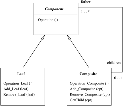
Operations (methods) are defined in the different classes. The set of components of a composite object is given by the GetChild method. Operation is a generic operation and deals with both leaf and composite objects. This operation is redefined in the Composite and Leaf classes by Operation_Composite and Operation_Leaf.
Figure 2 presents the class diagram of the Resource Allocation pattern described in [5]. Four classes are defined. The Resource class represents a resource to allocate. A resource provides facilities, represented in this pattern by the ResourceFacility class. A resource is allocated to job occurrences represented by the JobOccurrence class. Finally, JobCategory, which stands for the job categories, is linked to the last two classes. The requirements of the resource facilities are supported only by specific job categories. A job is represented by an association between JobOccurrence and JobCategory.

2.2 Design by Reuse
To motivate the need for reuse of specification patterns, we use the simple example of designing in UML the allocation of directories to secretaries. A directory is composed of files and other directories. Figure 3 gives a solution obtained by “instantiating” both patterns Composite and Resource Allocation. In the first pattern, a directory is considered as a Composite object and a file as a Leaf object. The Component class is renamed as Element (note that we could have kept the name Component). In the pattern Resource Allocation, an element is considered as a Resource object and a secretary as a JobCategory object.
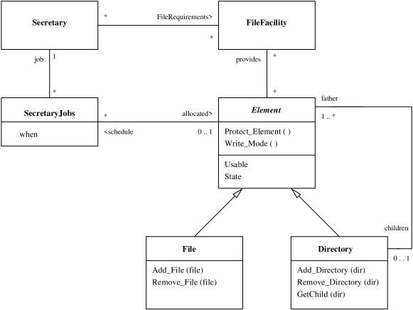
Compared to both original patterns, some operations are renamed. For instance, Add_Composite becomes Add_Directory in Fig. 3. Other operations such as Protect_Element and Write_Mode are created once the patterns have been instantiated. New variables called State and Usable are introduced to describe the protection mode of a file or a directory which is declared as usable.
2.3 Main Operations on Patterns
Two kinds of operations can be distinguished: pattern definition and mechanisms for reusing patterns.
Pattern Definition.
Two ways exist to define a new pattern. The pattern can either be defined “ex nihilo” or it can be deduced from existing patterns: this kind of reuse is aiming to create new patterns. In this case, mechanisms are defined at the pattern level in order to link and compare several patterns.
Reuse Mechanisms.
Three basic mechanisms exist for reusing patterns in order to design an application: instantiation, composition and extension [16]. They allow patterns to be adapted to the design in progress.
-
•
The instantiation, also called imitation, is a mechanism which allows different elements of a pattern to be renamed.
-
•
The composition mechanism, also called integration mechanism, associates two or more patterns. Different kinds of association may be defined.
-
•
The last reuse mechanism, called extension, allows new elements to be added to existing patterns or existing elements to be removed or modified.
Formal specification languages are very well adapted to define all these mechanisms. In the following sections, we present different existing propositions, before describing our solution.
3 State of the Art of Pattern Reuse with Formal Methods
Up to now, our research works deal with the use of formal methods in order to verify functional properties of systems (especially information systems [9]). Taking into account dynamic properties is a work in progress [6]. Therefore, in this paper, we do not consider event or temporal logic based formal methods such as [10, 14].
We have chosen to present four examples of formal methods that have been used to formalise design patterns and their reuse. For each of them, the following criteria are studied: presentation of the approach, pattern definition, available reuse mechanisms and their definition, existence of tools, usability of the approach, in particular the required mathematical background and the level of abstraction patterns that are defined and reused. More details can be found in [8].
3.1 UML-B Patterns Reuse
Pattern Definition.
Patterns are defined in two ways. In [12], patterns are defined “ex nihilo”. The UML diagram of a GoF pattern is translated from UML to B using a set of rules. Thus the B specification can be proved, using a B tool. In [13], a pattern can be defined as a refinement (also called specialisation) of a more generic pattern, thanks to the refinement mechanism of the B method.
Reuse Mechanisms.
The instantiation of a pattern is defined on the UML description of a pattern. The resulting diagram is again translated to B with the set of rules. This process has not been formalised, so the resulting B specification must be proved again.
Tools.
A tool based on the B and UML environments has been developed. No specific tools are defined to implement the reuse.
Usability.
This approach requires knowledge of UML and B. Pattern reuse is defined on the UML representation. Consequently, reuse mechanisms cannot be formally defined. Proofs associated with a pattern cannot be directly reused to achieve the proofs of its instantiation. However the definition of patterns by refinement of other patterns is quite interesting and original.
3.2 Frameworks in Catalysis
Catalysis [11] is a component-based specification method. Framework is the name used for pattern in Catalysis. The idea is to formally specify the frameworks by adapting the existing Catalysis features.
Pattern Definition.
A specification framework is defined with algebraic specifications using many-sorted first order logic. Axioms concerning the framework are specified in Catalysis with first order logic predicates. Rather than considering the initial model traditionally used in algebraic specifications as the referring model for the framework semantics, the theory is here represented by an isoinitial model which is very interesting, especially for proving formulas using negation, because it preserves the negation property contrary to the initial model111In an initial theory, the falsity of a ground atom corresponds to the non-provability of , while in an isoinitial theory, it corresponds to the provability of .. Nevertheless, the existence of the isoinitial model cannot be always guaranteed and axioms must be added to ensure its existence.
Reuse Mechanisms.
The instantiation is implemented by parameterisation. A parameter is a sort or a relation between sorts. Additional axioms involving parameters are defined. The axioms must be satisfied by the instantiation of parameters.
The frameworks composition is likewise. A parameterised framework may be composed with a parameterised framework if the involved axioms are satisfied. Firstly, a renaming map is defined from to . The aim is to link each element of the signature to one element of the signature. Then the framework resulting from the composition of and is characterised as follows : its signature is the renamed signature of and its axioms are the union of the axioms of and . Note that this composition is associative but not commutative.
Tools.
No other tools than those existing in the Catalysis approach are used.
Usability.
This approach formally defines the notions of framework specification, instantiation and composition. The choice of adapting an existing approach (Catalysis) is interesting because it avoids the introduction of new languages or tools. The isoinitial theory chosen for the framework semantics simplifies the soundness proof. However, additional axioms must be defined in order to ensure that an isoinitial model exists. Furthermore, it requires knowledge about algebraic specification and about isoinitial theories.
3.3 Pattern Specification with RSL
The idea of this approach is to formalise with RSL (RAISE Specification Language) [4] design patterns described by UML diagrams. RSL is based on VDM and an algebraic specification language.
Pattern Definition.
A formal model of pattern is defined. It represents a pattern as a head, a structure and a list of collaborations. The head section describes the name, purpose and scope of the pattern. The pattern structure specifies the classes and associations in RSL. In the last section, the list of collaborations specifies constraints on the order of operation calls.
Reuse Mechanisms.
The instantiation mechanism is implemented by a renaming map. However, a pattern can be instantiated only once. The resulting RSL specification can then be extended by new elements. The composition mechanism is only illustrated through examples.
Tools.
To our knowledge, no tool has been implemented.
Usability.
Patterns for oriented-object programming have been studied extensively in this approach. That is why a lot of oriented-object programming features have been specified, thus giving specifications described at a low level of abstraction.
3.4 LePUS, a Language for Patterns Specification
The idea in this approach is the definition of a new formal language, LePUS (LanguagE for Patterns Uniform Specification) [3], dedicated to the specification of patterns. This language is based on higher order monadic logic (HOML).
Pattern Definition.
The aim is to formalise the GoF patterns. The main properties of these patterns are expressed by higher order predicates built on higher order sets of classes and methods. A pattern is then represented by a conjunction of predicates. New patterns can be defined from existing ones by projection of the higher order sets. Roughly speaking, a projection consists in reducing the order of a set. Thus, these patterns are more concrete than the original ones.
Reuse Mechanisms.
The instantiation of a pattern consists in instantiating the sets involved in the pattern predicate.
Tools.
To our knowledge, no tool has been implemented.
Usability.
This approach needs a strong background in mathematics. Moreover, this very formal method is difficult to apply, because the user must exhibit classes, methods and higher order sets in order to define an instance of a pattern. Defining a higher order set means defining all the sets with a lower order level and so on up to classes and methods.
3.5 State of the Art: Conclusion
Table 1 is a comparison between the four above-mentioned approaches and our approach, presented in the next section.
| Approach | UML-B | Framework | RSL | LePUS | Ours |
| Section | 3.1 | 3.2 | 3.3 | 3.4 | 4 |
| Specification | UML and | algebraic | VDM | HOML | B |
| models: | B machines | specification | |||
| Direct | UML to B | isoinitial | RSL | conjunction | B machine |
| Definition | translation | theory | formal | of predicates | |
| of Pattern: | model | ||||
| Pattern | refinement | no | no | projection | no |
| Definition | |||||
| by Reuse: | |||||
| Instantiation: | UML | parameters | map | parameters | inclusion |
| and renaming | |||||
| Composition: | UML | not | no | no | inclusion and |
| commutative | new invariant | ||||
| Extension: | UML | no | yes | no | inclusion and |
| refinement | |||||
| Tools: | UML and | Catalysis | no | no | B tools |
| B tools | |||||
| Usability |
The LePUS approach is the most advanced specification method for defining and instantiating design patterns, but it is also the most difficult to apply. The instantiation notion is defined in all the approaches: by the UML instantiation mechanism for UML-B, by parameterised frameworks for Catalysis, by a renaming map for RSL and by an instantiation of parameters for LePUS. The composition mechanism seems to be more difficult to define, since only a non commutative operation is defined for frameworks. The extension is only treated by RSL and UML-B. Even if the UML-B approach seems to be close to our work, it differs significantly since the reuse mechanisms are not formally defined.
4 An Approach for Reusing Patterns in B
The aim of this section is to investigate the ability of B to specify patterns and the different reuse mechanisms. We have chosen to consider the B language as it is. This means that we want to define the reuse mechanisms only with the different B mechanisms such as refinement, inclusion, and so on. Thus, the proofs generated during the reuse process are only those generated by the corresponding B mechanisms.
For each mechanism, we present an implementation in B and its limits. We refer to the example presented in Sect. 2.2. The B specification is introduced step by step, the complete specification is given in [1].
The last subsection presents a summary of the proof activity generated by the approach.
4.1 Definition of Patterns
The way a pattern is defined is strongly dependent on how the reuse mechanisms are defined. Ideally, a pattern should be specified by several machines (for instance, one machine for each class of the UML diagram), all included in a machine which stands for an interface of the pattern (see UML-B approach in Sect. 3.1 and [15]).
For technical reasons, some B mechanisms such as refinement require the use of a single abstract machine. Consequently, a pattern is specified by a single abstract machine. This is a first limit of our approach, and perhaps the more annoying one.
In order to implement the composition mechanism (see Sect. 4.3), the given sets of the pattern must be specified as parameters of the machine. For instance, the Composite pattern is specified with the following Composite_Pattern machine:
- MACHINE
-
Composite_Pattern(COMPONENT)
- VARIABLES
-
Component, Composite, Leaf, Father
- INVARIANT
-
-
Component COMPONENT
-
Composite Component
-
Leaf Component
-
Father Component Composite
-
Leaf Composite Component
-
Leaf Composite
-
-
…
- OPERATIONS
-
children GetChild(father) …
-
cpt New_Composite(comp) …
-
Add_Composite(cpt,comp) …
-
leaf New_Leaf …
-
Add_Leaf(leaf) …
-
Remove_Composite(cpt) …
-
Remove_Leaf(leaf)
-
pre
leaf Leaf
leaf dom(Father) -
then
… -
end
-
Operation(cpt) …
The variables Component, Composite and Leaf represent three classes, while the variable Father stands for the association link between the UML classes Component and Composite (see Sect. 2.1). The types of the classes and associations are formally specified in the B invariants. In the same way, the Resource Allocation pattern is specified in B.
- MACHINE
-
Resource_Allocation(JOBS, CATEGORY,
FACILITY, RESOURCE) - SETS
-
DATE
- VARIABLES
-
-
JobOccurrence, When, JobCategory, Resource, ResourceFacility,
-
Job, Requirements, Provides, Allocated
-
- INVARIANT
-
-
JobOccurrence JOBS
-
When JobOccurence DATE
-
…
-
- OPERATIONS
-
Add_Resource(res) …
-
Remove_Resource(res)
-
pre
res RESOURCE -
then
Resource Resource res
Provides res Provides
Allocated Allocated res -
end
-
…
4.2 Instantiation Mechanism
The instantiation mechanism is implemented in B by the inclusion of machines. The machine corresponding to the pattern is included in the machine corresponding to the instantiation of the pattern.
In the example, the machine Directory_Renaming includes the machine of the Composite pattern. The given sets, defined as parameters of the machine, can be renamed by instantiation of the parameters. In our example, COMPONENT is renamed by ELEMENT:
- MACHINE
-
Directory_Renaming
- SETS
-
ELEMENT
- INCLUDES
-
Composite_Pattern(ELEMENT)
-
…
The DEFINITIONS clause allows us to rename variables from the included machine. Composite and Leaf are respectively renamed by Directory and File.
- DEFINITIONS
-
-
Directory Composite
-
File Leaf
-
Renaming operations is not so straightforward. There are two cases. Firstly, if an operation is directly reused without renaming we use the PROMOTES clause. Secondly, a renamed operation is specified in the OPERATIONS clause. It consists of a call statement to the corresponding pattern operation. In our example, the Remove_Leaf operation is renamed by Remove_File:
- OPERATIONS
-
Remove_File(file)
-
pre
file File
file dom(Father) -
then
Remove_Leaf(file) / operation defined in Composition_Pattern / -
end
The preconditions must be the same as those of the called operation, except that the variables and sets are the renamed ones.
4.3 Composition Mechanism
A first step is to precisely define the composition mechanism. We distinguish three levels of composition according to whether or not there exist links between the composed patterns. In the three cases, composition is achieved by the inclusion mechanism of B: all the machines representing the composed patterns are included in the machine representing the composition, called the composition machine.
Juxtaposition.
Patterns are composed without defining any link between them. This composition is only a juxtaposition of each pattern. We use the EXTENDS mechanism which allows all the operations of the two composed patterns to be considered as genuine operations of the composition machine:
- MACHINE
-
Composition_By_Juxtaposition
- SETS
-
COMPONENT; JOBS; CATEGORY; FACILITY; RESOURCE
- EXTENDS
-
-
Composite_Pattern(COMPONENT),
-
Resource_Allocation(JOBS, CATEGORY, FACILITY, RESOURCE)
-
-
…
Composition with Inter-Patterns Links.
New relations between variables of the composed patterns can be added. For instance, a bijection called CompRes may be defined between Component (from Composite_Pattern) and Resource (from Resource_Allocation).
- MACHINE
-
Composition_By_InterPatterns_Links
- SETS
-
COMPONENT; JOBS; CATEGORY; FACILITY; RESOURCE
- INCLUDES
-
-
Composite_Pattern(COMPONENT),
-
Resource_Allocation(JOBS, CATEGORY, FACILITY, RESOURCE)
-
- VARIABLES
-
CompRes
- INVARIANT
-
CompRes Component Resource
According to the type of the new variables, the operations of the composed patterns involving the linked variables must be modified. For instance, the operation Remove_Leaf from Composite_Pattern removes a leaf from Component. This operation cannot be only renamed in the machine Composition_By_InterPatterns_Links. It must be composed with the operation Remove_Resource from Resource_Allocation and with a substitution on the variable CompRes in order to preserve the new invariant. The resulting operation is Remove_Thing_1:
-
Remove_Thing_1(thing)
-
pre
thing Leaf
thing dom(Father) -
then
Remove_Leaf(thing)
Remove_Resource(CompRes(thing))
CompRes thing CompRes -
end
A composition mechanism between operations must be defined. It could be automated provided that each composed pattern specifies the elementary operations to be composed on each variable.
Other operations of the composed patterns can be promoted to become genuine operations of the composition machine.
Unification.
This composition allows some variables of the composed patterns to be merged. Up to now, only variables corresponding to classes or associations in the patterns may be unified. This property is specified in the INVARIANT clause of the composition machine. Two variables may be unified only if they have the same type, that is why we need to define the given sets as parameters of a pattern machine (see Sect. 4.1). For example, we can compose the two patterns Composite_Pattern and Resource_Allocation by unifying the variables Component and Resource. This yields the following machine:
- MACHINE
-
Composition_By_Unification
- SETS
-
ELEMENT; JOBS; CATEGORY; FACILITY
- INCLUDES
-
-
Composite_Pattern(ELEMENT),
-
Resource_Allocation(JOBS, CATEGORY, FACILITY, ELEMENT)
-
- INVARIANT
-
Component Resource
Let us note that the parameters COMPONENT and RESOURCE are now replaced by the same set called ELEMENT.
As in the composition by inter-patterns links, operations of the composed patterns involving the unified variables must be redefined. The operation Remove_Leaf involves the variable Component which is now unified with Resource. Then the operation resulting from the composition is:
-
Remove_Thing_2(thing)
-
pre
thing Leaf
thing dom(Father) -
then
Remove_Leaf(thing)
Remove_Resource(thing) -
end
From a methodological point of view, an instantiation and a composition can be achieved in one step, before applying the extension mechanism. For the next subsection, we assume that firstly we have composed the two patterns Composite_Pattern and Resource_Allocation by unifying the variables Component and Resource and secondly instantiated them by renaming elements with the names used in the class diagram of Fig. 3. The resulting B machine is called Comp_By_Unif_Inst:
- MACHINE
-
Comp_By_Unif_Inst
- SETS
-
ELEMENT; JOBS; CATEGORY; FACILITY
- INCLUDES
-
-
Composite_Pattern(ELEMENT),
-
Resource_Allocation(JOBS, CATEGORY, FACILITY, ELEMENT)
-
- DEFINITIONS
-
-
Directory Composite;
-
File Leaf;
-
SecretaryJobs JobOccurrence;
-
Secretary JobCategory;
-
FileFacility ResourceFacility;
-
FileRequirements Requirements;
-
Element Resource
-
- INVARIANT
-
Component Resource
-
…
- PROMOTES
-
GetChild
- OPERATIONS
-
dir Add_Directory(files) …
-
file Add_File …
-
Remove_Directory(dir) …
-
Remove_File(file) …
-
…
In this machine, the above-mentioned operation Remove_Thing_2 is renamed by Remove_File.
4.4 Extension
Most often an extension consists in defining new variables, modifying existing operations to take into account these new variables and adding new operations, in the result of a composition and/or an instantiation, specified in a B machine called the before-extension machine. Two solutions exist to implement this mechanism in B, with arguments on both sides. The first solution consists in including the before-extension machine into a new machine. The main drawback is that we cannot modify an included operation. Then, if we want to modify an operation of the before-extension machine, we need to rename it. We prefer using the refinement mechanism with the idea of adding more details to a specification. We will see later the limits of the refinement mechanism.
Let us take our example: the machine Comp_By_Unif_Inst which is the before-extension machine is refined by the machine Extension.
- REFINEMENT
-
Extension
- REFINES
-
Comp_By_Unif_Inst
- SETS
-
ELEMENT; JOBS; SECRETARY; FILEFACILITY;
STATE write,protected - INCLUDES
-
-
Composite_Pattern(ELEMENT),
-
Resource_Allocation(JOBS, SECRETARY, FILEFACILITY,
ELEMENT)
-
- VARIABLES
-
State, Usable
- INVARIANT
-
-
Usable Element
-
State Usable STATE
-
- INITIALISATION
-
Usable, State ,
-
…
Existing operations may be extended in only one way: new substitutions using the new variables can be specified. For instance, Remove_File is refined by:
-
Remove_File(file)
-
pre
file File
file dom(Father) -
then
Remove_Leaf(file) Remove_Resource(file)
Usable Usable file State file State -
end
New operations cannot be added during the refinement process. Thus, in order to define a new operation, two solutions are possible. Either the before-extension machine is extended with the EXTENDS clause, to add new operations, specified as “skip”. Or the before-extension machine is modified by adding these new operations also specified as “skip”. For the sake of concision, we present the second option. Then, in both cases, each new operation is refined with new substitutions involving only new variables that are not related to variables in the gluing invariant and with calls to operations of the included machines. The refinement is then correct.
In our example, the new operation Protect_Element sets the state of an element to protected. This operation is defined in the Comp_By_Unif_Inst machine by:
-
Protect_Element(el)
-
pre
el Element -
then
skip -
end
The operation is then refined in the machine Extension by:
-
Protect_Element(el)
-
pre
el Element -
then
State(el) protected Usable Usable el -
end
4.5 Summary and Analysis of the Proof Activity
The machines corresponding to the different patterns (Composite_Pattern and Resource_Allocation) have been proved with the Atelier B [2] (see Tab. 2). We will now present a summary of the proofs generated by the reuse mechanisms.
The instantiation mechanism does not generate new proof obligations since nothing new has been specified. By construction, operations are automatically proved. Thus the proofs of the machine corresponding to an instantiation are obvious: they have already been proved in the included machine.
The composition by juxtaposition of different machines gives a machine which is automatically proved, since nothing new has been specified. The compositions with inter-patterns links and by unification generate proof obligations which are to be automatically discharged if the composition of operations has been correctly elaborated.
For the extension mechanism, the new proof obligations concern, on one hand, the invariants and operations which have been added and, on the other hand, the refinement of the modified operations.
Table 2 summarises the proofs of the example described in Sect. 4.4. nObv is the number of obvious proofs generated and trivially discharged by the Atelier B. nPO represents the number of proof obligations (PO) to discharge. nAut represents the number of POs automatically discharged and nInt the number of POs interactively discharged. All the interactive proofs have been discharged.
| Machines | nObv | nPO | nAut | nInt |
| Composite_Pattern | 32 | 59 | 47 | 12 |
| Resource_Allocation | 42 | 16 | 15 | 1 |
| Comp_By_Unif_Inst | 43 | 10 | 10 | 0 |
| Extension_Machine | 284 | 33 | 23 | 10 |
For Extension_Machine, only ten proofs have been interactively proved. Six proof obligations are linked to the preservation of the following invariant:
-
State Usable STATE
These proof obligations depend on the new specifications introduced in the refinement: they are linked to the extension mechanism.
Four proof obligations concern the refinement of operations. These four proof obligations have been proved in the same way: their goal is false because one of their hypotheses is false. Whatever the extension is, this kind of proof obligations is always generated: the proof obligations do not depend on the new specifications, but on the refinement mechanism. Once they have been proved, we can use the same strategy in order to prove them again in another extension.
In comparison with our approach, we have specified the same example (see Fig. 3) directly in B without using patterns. The resulting machine, called Direct_Example, has been proved with the Atelier B (see Tab. 3 for the proofs result). The complete specification can be found in [1].
| Machines | nObv | nPO | nAut | nInt |
|---|---|---|---|---|
| Direct_Example | 167 | 87 | 67 | 20 |
For the same example, the Direct_Example machine obviously requires less proof activity than with our pattern reuse method, since only one abstract specification is used compared to the two specification patterns, the before-extension machine and the refinement used in our approach. However, if we assume that the two specification patterns are previously specified and proved, our approach requires only forty-three POs () which have to be compared to the eighty-seven for the direct specification. Moreover, once POs have been automatically discharged, only ten POs () must be interactively proved in our approach by pattern reuse, compared to the twenty POs that must be interactively discharged for the Direct_Example machine.
In conclusion, since four POs are “reusable” in our approach, the reuse of specification patterns to specify the example described in Sect. 2.2 allows us to save fourteen POs to interactively discharge, provided that the two specification patterns Composite_Pattern and Resource_Allocation are previously specified and proved. Let us note that the Direct_Example machine is inspired by the result of the specification by pattern reuse described in Fig. 3. One would have undoubtedly specified the same example differently and consequently the generated proofs could be different.
5 Conclusion, Limits and Perspectives
In this paper, we have presented an approach for reusing patterns with the B method. We have implemented the different mechanisms linked to the reuse of patterns by using only the B mechanisms. It is interesting because the mechanisms are formally defined and we can benefit from the advantages of the B method, especially the “reuse” of proofs and the tool. There are two major drawbacks. The first one is that a pattern is defined in one machine, which can produce a big machine, difficult to read and maintain. The second one is the obligation of defining the new operations of an extension before actually applying the extension mechanism.
Concerning the pattern reuse mechanisms, the composition of several instances of the same pattern has not been studied. We also have to precisely define the mechanism of operations composition. The following necessary step will be the development of a tool to assist the designer during the specification of an application by pattern reuse. The example presented in this paper is rather simple. However, the used patterns are those described in [7], which are patterns largely tested in real designs. A more complex example just involves more patterns but the method presented in the paper is still applicable, provided that a tool is available.
In this paper, we have introduced the notion of reuse of proofs. The aim is to define the notion of proof linked to a machine and to specify the reuse of proofs with the B method. This perspective is new, since the reuse of proofs is not possible with a formal method like B. However, such a possibility requires several works on new examples in order to analyse the consequences on the proof obligations.
References
- [1] Blazy, S., Gervais, F., Laleau, R.: Un exemple de réutilisation de patterns de spécification avec la méthode B. Techn. rep. 395, CEDRIC Laboratory, Évry, France, 2002. Available at http://cedric.cnam.fr/PUBLIS/RC395.ps.gz
- [2] Clearsy: http://www.atelierb-societe.com
- [3] Eden, A., Hirshfeld, Y., Yehudai, A.: LePUS - a declarative pattern specification language. Techn. rep. 326/98, Department of Computer Science, Tel Aviv University, 1998.
- [4] Flores, A., Reynoso, L., Moore, R.: A formal model of object-oriented design and GoF design patterns. Techn. rep. 200, UNU/IIST, Macau, 2000. Available at http://www.iist.unu.edu/
- [5] Fowler, M.: Analysis patterns: reusable object models. Addison-Wesley, 1997.
- [6] Frappier, M., Laleau, R.: Proving Event Ordering Properties for Information Systems. Proc. ZB2003, LNCS, Springer-Verlag, Turku, Finland, June 4-6, 2003.
- [7] Gamma, E., Helm, R., Johnson, R., Vlissides, J.: Design patterns: elements of reusable object-oriented software. Addison-Wesley, 1995.
- [8] Gervais, F.: Réutilisation de composants de spécification en B. Master’s thesis, DEA IIE(CNAM)-University of Évry-INT, Évry, France, July 2002. Available at http://cedric.cnam.fr/PUBLIS/RC394.ps.gz
- [9] Laleau, R., Mammar, A.: An overview of a method and its support tool for generating B specifications from UML notations. Proc. ASE: 15th IEEE Conference on Automated Software Engineering, IEEE Computer Society Press, Grenoble, France, September 2000.
- [10] Lano, K., Bicarregui, J., Goldsack, S.: Formalising Design Patterns. Proc. BCS-FACS Northern Formal Methods Workshop, Springer-Verlag, 1997, Ilkley, United Kingdom, September 3-4, 1996.
- [11] Lau, K., Ornaghi, M.: OOD frameworks in component-based software development in computational logic. Proc. LOPSTR’98, LNCS 1559, pages 101–123, Springer-Verlag, 1999, Manchester, United Kingdom, June 15-19, 1998.
- [12] Marcano, R., Meyer, E., Levy, N., Souquieres, J.: Utilisation de patterns dans la construction de spécifications en UML et B. Proc. AFADL’2000: Approches formelles dans l’assistance au développement de logiciels, Tech. rep. A00-R-009, LSR Laboratory, Grenoble, France, January 26-28, 2000.
- [13] Marcano-Kamenoff, R., Levy, N., Losavio, F.: Spécification et spécialisation de patterns en UML et B. Proc. LMO’2000: Langages et modèles à objets, Hermès Science Publications, Mont Saint-Hilaire, Québec, Canada, January 25-27, 2000.
- [14] Mikkonen, T.: Formalizing design patterns. Proc. of the 20th International Conference on Software Engineering, IEEE Computer Society, pages 115–124, Kyoto, Japan, April 19-25, 1998.
- [15] Nguyen, H.P.: Dérivation de spécifications formelles B à partir de spécifications semi-formelles. Ph.D. Thesis, CEDRIC Laboratory, CNAM, Évry, France, 1998. Available at http://www.iie.cnam.fr/~laleau/
- [16] Prieto-Diaz, R., Freeman, P.: Classifying software for reusability. IEEE Software, 4(1), pages 6–16, January 1987.