A Locating-First Approach for Scalable Overlay Multicast
Abstract
Recent proposals in multicast overlay construction have demonstrated the importance of exploiting underlying network topology. However, these topology-aware proposals often rely on incremental and periodic refinements to improve the system performance. These approaches are therefore neither scalable, as they induce high communication cost due to refinement overhead, nor efficient because long convergence time is necessary to obtain a stabilized structure. In this paper, we propose a highly scalable locating algorithm that gradually directs newcomers to their a set of their closest nodes without inducing high overhead. On the basis of this locating process, we build a robust and scalable topology-aware clustered hierarchical overlay scheme, called LCC. We conducted both simulations and PlanetLab experiments to evaluate the performance of LCC. Results show that the locating process entails modest resources in terms of time and bandwidth. Moreover, LCC demonstrates promising performance to support large scale multicast applications.
I Introduction
A key factor to “overlay networking” success is that an overlay service can be quickly constructed and easily deployed and upgraded. In particular, several overlays support multicast-style data dissemination service without requiring the widespread deployment of IP multicast. However, such application-level multicast may suffer from poor performance, scale and cost problems when the delivery tree construction process ignores the topology and link characteristics of the underlying network. If an overlay is built in this way, nearby nodes in the overlay network may actually be distant from each others in the underlying network. Recent proposals in multicast overlay construction [1-10] demonstrate the importance of exploiting underlying network topology. However, we claim that there are barriers for quality of service aspects, namely scalability and efficiency in existing topology-aware overlay multicast protocols:
-
1.
Although decentralized protocols have been designed to be scalable, by not relying on global knowledge, they often rely on periodic and incremental refinement processes, which induce high overhead. In these protocols such as [1] [2] [3] [4], nodes maintain their relative positions to the root of the delivery tree. Periodically, each node tries to improve its on-tree position by finding a better parent, i.e. a non-descendant node that provides a lower delay to the root. Therefore, these protocols are generally not scalable to support large multicast groups. Additional overhead is incurred in case of dynamicity of either the overlay membership or the underlying network conditions. In fact, during overlay growth or membership changes, heavy control overhead is incurred due to periodical structure quality maintenance and partition repairs operations. On the other hand, higher frequency control messages is required to map the overlay to varying network characteristics.
-
2.
Users attending a video conferencing session or an event broadcast expect an acceptable quality as soon as they join the multicast session. Since a multicast overlay delivery tree is typically studied to minimize the average incurred delay observed by the receivers, we consider that a delivery tree is “efficient” if the average incurred delay is less than a threshold value. However, one would expect that incremental refinements-based approaches incur a long delay before the overlay delivery tree converges to an efficient structure.
In this paper, we provide a practical solution for large-scale and efficient multicast support. First, we propose a simple and accurate location-aware process for connecting new members to the overlay network. The basic idea is to use the nodes in the already constructed overlay to suggest candidate neighbors that are close to a newcomer. The latter gradually requests the suggested nodes to refine its localization in the underlying network. This locating process does not use virtual coordinates system embedding nor fixed landmarks measurements, and aims to be accurate and scalable.
Second, we build a robust and scalable topology-aware clustered hierarchical overlay on the basis of the locating process. We propose proactive mechanisms to react to cluster leaders failures, and to smoothly manage overlay topology changes caused by crash scenarios or underlying network changes. Scalability is achieved by drastically reducing the bandwidth requirements for overlay maintenance. Robustness is obtained by mitigating the effect of dynamic environment as most changes are quickly recovered and not seen beyond clustered set of nodes. The proposed overlay multicast construction scheme, called Locate, Cluster and Conquer (LCC), has been designed to address the aforementioned quality of service issues. Intuitively, running the locating process before that the node joins the overlay, and then clustering nearby nodes should allow to perform fast convergence to an efficient multicast delivery tree. Furthermore, it would reduce management overhead and delivery tree changes imposed due to periodical refinements. However, these enhancements could be mitigated by the overhead of the locating process.
Taking into account these considerations, we evaluated the LCC scheme using two complementary evaluation methods: simulations and experimentations over the PlanetLab testbed. Results show that LCC has low overhead upon the locating process and during the session. Compared to other initially-randomly and topology-aware approaches, LCC achieves lower convergence time and performs less link adjustments rate. At the same time, it performs well in terms of data distribution efficiency even in large overlays.
The remainder of this paper is structured as follows. Section 2 presents the related work. Section 3 provides an overview of the LCC scheme. The locating process is detailed in Section 4. Then the clustering mechanism and its different components are presented in Section 5. Experiments and simulations are discussed in Section 6 and a comparison with various previous approaches is provided. Finally, Section 7 concludes the paper.
II Related Work
There has been tremendous interest in the construction of overlays to provide application-level multicast. Basically, the contributions can be categorized in two classes: overlay-router approach and P2P approach.
In the overlay-router approach such as OMNI [5] and TOMA [6], reliable servers are installed across the network to act as application-level multicast routers. The content is transmitted from the source to a set of receivers on a multicast tree consisting of the overlay servers. This approach is designed to be scalable since the receivers get the content from the application-level routers, thus alleviating bandwidth demand at the source. However, it needs dedicated infrastructure deployment and costly servers.
The P2P approach requires no extra resources. Several proposals have been designed to handle small groups. Narada [1], MeshTree [4], and Hostcast [3] are examples of distributed “mesh-first” algorithms where nodes arrange themselves into well-connected mesh on top of which a routing protocol is run to derive a delivery tree. These protocols rely on incremental improvements over time by adding and removing mesh links based on an utility function. Although these protocols offer robustness properties (thanks to the mesh structure), they do not scale to large population, due to excessive overhead resulting from the improvement process. The objective of LCC is to locate the newcomer prior to joining the overlay and hence process only a few number of refinements during the multicast session.
Other “tree-first” protocols like ZigZag [7] and NICE [8], are topology-aware clustering-based protocols which are designed to support wide-area size multicast for low bandwidth application. However, they do not consider individual node fan-out capability. Rather, they bound the overlay fan-out using a (global) cluster-size parameter. In particular, since both protocols only consider latency for cluster leader selection, they may experience problems if the cluster leader has insufficient fan-out. Other proposals exploit the AS-level [9] or the router-level [10] underlying network topology information to build efficient overlay networks. However, these approaches assume some assistance from the IP layer (routers sending ICMP messages, or BGP information access), which may be problematic. LCC does not require any extra assistance from entities that do not belong to the overlay.
Landmark clustering is a general concept to construct topology-aware overlays. Ratnasamy et al. [11] use such an approach to build a multicast topology-aware CAN overlay network. Prior to joining the overlay network, a newcomer has to measure its distance to each landmark. The node then orders the landmarks according to its distance measurements. The main intuition is that nodes with the same landmark ordering, are also quite likely to be close to each other topologically. An immediate issue with such a landmark-based approach is that it can be rather coarse-grained depending on the number of landmarks used and their distribution. Furthermore, requiring a fixed set of landmarks known by all participating nodes renders this approach unsuitable for dynamic networks.
III Overview of LCC
We have designed a two-level clustered overlay multicast architecture (LCC) to provide scalable, efficient and robust multicast distribution service to end users. Basically, the LCC overlay construction is divided into two processes: Locating and Clustering.
The locating process aims to direct newcomers to the “nearest” cluster before they receive data on the delivery tree. A newcomer initiates the locating process by sending a “Localization_Request” to a randomly selected cluster leader (denoted by boot node). According to its location-information knowledge, the boot node selects a few cluster leaders (that we will denote the queried nodes) that it considers to be close to the newcomer. It asks them to probe the newcomer, and gets each queried node’s answer. Then, it suggests to the newcomer the possible closest nodes. By iteratively sending “Localization_Request” messages to the closest nodes (called the requested nodes in the rest of the paper), the newcomer is able to gradually locate nodes that are close by. Each requested node uses a selection criterion to limit the number of nodes probing the newcomer, hence minimizing the locating overhead. The locating process ends by proposing one or more nearby cluster leaders.
By grouping together nodes that are close to a cluster leader, members are expected to be close to each other, which leads to low overhead of intra-cluster control messages. The clustering process is initiated by every node once the locating process terminates. On the basis of their locating result, nodes are partitioned into clusters of nodes. A maximum distance, , defines the interval in which other nodes are considered “nearby”. This interval is called the cluster leader’s scope, and defines the clustering criterion. During the clustering process, a node decides at which level it will join the overlay. If it creates its own cluster, it joins the “top-level” topology and starts an inter-cluster mesh construction. Otherwise, it becomes a cluster member and joins an intra-cluster mesh in order to derive its delivery tree.
Since a node could be in more than one cluster leader’s scope, it could be member of more than one cluster. Such nodes are called edge nodes. We exploit edge nodes to improve the overlay efficiency. In fact, the cluster leader is the primary responsible of connecting its cluster to the top-level overlay. Nevertheless, edge nodes are also allowed to join the inter-cluster mesh at the top level. The main role of edge nodes is to allow (if fan-out constraints are not violated) the clusters members to derive their delivery tree considering the edge node as an alternative nearby source connected to the top-level topology. Moreover, these nodes may contribute in the overlay robustness in case of cluster leaders failures. Although edge nodes are attached to several meshes of different clusters, they do not receive the data several times. In fact, as each edge node derives a unique delivery tree from one of the existing intra-cluster mesh, it is then a child in this particular delivery tree. On the other hand, it could be a parent in several derived delivery trees in other clusters. A high level picture of LCC is illustrated in Fig. 1.
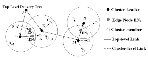
Note that LCC does not specify a new tree construction protocol; any existing protocol may be used on top of LCC. In this paper, we choose to construct the LCC overlay by running the MeshTree protocol [4] at both the top-level and the intra-cluster level. MeshTree embeds the delivery tree in a degree-bounded mesh containing many low-cost links. The constructed mesh consists then of two main components: (i) a backbone structure, composed of a low-cost tree and connecting nodes that are topologically close together, and (ii) additional links to improve the delay properties. The delivery tree is then derived from the mesh using a path-vector routing protocol. The “Flat” MeshTree first constructs a randomly connected overlay and relies on periodical adding/deleting links using a set of local rules. Unlike this approach, the LCC scheme, initially constructs location-aware overlay based on the locating and clustering processes. Top-level nodes then act as particular MeshTree nodes, where other clusters represent neighbors in the derived delivery tree (see Fig. 1).
In order to construct an overlay spanning tree rooted at the source node , we need to consider the degree constraints. Assuming that the media playback rate is and the outgoing access link capacity of any particular node , is , the total number of streams that the node can handle is = []. The fan-out value of node represents the maximum number of connections that this node can establish with other nodes. We assume that each node can estimate its connection type (eg ADSL, 802.11, etc.), relying on system and user specifications. Moreover, LCC can use a history of maximum throughput of the most recent downloads, as an indication of its effective connection speed. These fan-out estimation techniques are used in order to avoid each node to measure its available bandwidth, which may involve high overhead. We also define the cluster overall capacity as , where is the number of members in the clusters. Next, we detail both the locating and the clustering LCC processes.
IV The Locating Process
LCC adopts a nodes’ positioning strategy similar to meridian [12] to organize nodes into levels according to a distance metric. Typically, the distance between two nodes is the round trip network delay. Each LCC node keeps track of a fixed number of other nodes in its locating system. A locating system is a set of non overlapping and exponentially increasing levels, represented by intervals , where for and (see Fig. 2).
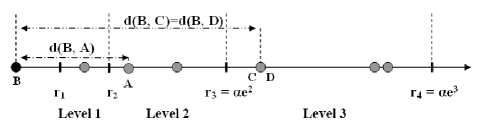
Nodes measure the distances to the set of nodes they are aware of, and assign each node a position in the correspondent level of their locating system. For example if the measured distance satisfies , the node is positioned in the level. All considered nodes in the locating system are cluster leaders. In the following, we describe the locating process operations.
IV-A Bootstrap and locating request
Initially, a newcomer, say node , has to contact a global well-known Rendezvous Point111or any equivalent mechanism. to obtain the identity of a randomly selected boot node, . Node measures the distance from itself to , and assigns a level in its locating system, say level . If is in ’s scope, i.e. , the clustering criterion is met and the locating process terminates, and sends a request to join ’s cluster. Otherwise, sends a “Localization_Request”. Upon receiving such request, the requested node simultaneously queries nodes that it considers as nearby to . These queried nodes have then to report the results back to the requested node. If a queried node is closer to the newcomer than the requested node, it is considered as a candidate. A list that identifies the set of candidate nodes is sent by the requested node to the newcomer . Among this list, initiates cluster joining processes with all nodes that meet the clustering criterion. If there are no such nodes in the list, nodes in the candidate list become possible requested nodes, since re-initiates the locating process with each node in this list sorted in increasing distances. The list is updated at each response from a requested node. This procedure is repeated until the newcomer finds a cluster leader in its scope. Finally, it is necessary to set a stop criterion to terminate the process within a given time period by repeating the procedure at most times. If the algorithm ends without satisfying the clustering criterion, creates its own cluster.
IV-B The selective-locating process
During the locating request, each requested node has to query a set of nodes. It then selects among them a list of candidate nodes to send to the newcomer. In this subsection, we answer the following question: How queried nodes are chosen by the requested node?
The basic solution would be that the requested node asks all the nodes in the same level than the newcomer and in the adjacent levels, as potential queried nodes. To establish a reference, we consider this solution that we call the “non-selective” locating process. Although it has the advantage of simplicity, this solution may induce high overhead. In fact, while being in the same or adjacent levels than the newcomer, some queried nodes should not be taken into consideration for probing the newcomer, since they may be not closer to it than the requested node.
We introduce the selection criterion in order to reduce the number of useless probes during the locating process. Basically, the “selective locating” consists in querying only specific representative nodes. Nodes that are close enough to a representative node, randomly selected by the requested node, are not queried to measure their distance to : the less queried nodes, the less measurements and control overhead.
Closeness is defined by a distance threshold value , which is a function of the distance between the newcomer and the requested node, . If the newcomer is close to the level frontier or to the requested node, the latter should use a fine-grained selection and a small value should be used. If not, the requested node should use a greater value. In our algorithm, we choose:
Nodes maintain for each level a square matrix, , representing learned distances of level ’s nodes to each other, and to nodes in adjacent levels and . Values in are assigned as and when discovered through other nodes’ locating requests. If a distance is not known, it is set to a value large enough to discard the concerned node from the selection. Each element in corresponds to the distance between nodes and . The row in represents the learned distances between node and other nodes in level and adjacent levels. The selection algorithm run by a requested node is presented in Algorithm 1
and can be described as follows: Each requested node selects a random node, , from level or adjacent levels. If is less than the threshold value , then node is represented by . Selected nodes are represented by a matrix, say , which is initially equal to . At each iteration of the selection process, is diminished by the columns of nodes in that can be represented by the selected node . The selection algorithm terminates when contains only distances of representative nodes.
V The Clustering Process
In this section, we describe the protocol to form and maintain clusters. In this work, we emphasize mechanisms to enhance the overlay QoS by increasing scalability and robustness. In particular, we propose a proactive algorithm to manage failures of leaders, and new cluster formation afterwards. We also propose new mechanisms to smoothly manage cluster topology changes due to leadership or underlying network changes.
V-A Cluster Creation
In early stage of the overlay formation, new clusters are more frequently generated since few nodes exist. If the locating process ends with no leaders found in the newcomer’s scope, the latter creates its proper cluster with a new cluster ID. It then contacts the closest cluster leaders that the locating process returns, to join the top-level topology. Contacted cluster leaders inform their members by flooding a “New_Cluster” message. Finally, members verify if they are in the new leader’s scope, i.e. if they are potential edge nodes.
V-B Cluster Joining
A classical joining operation is initiated by a newcomer detecting cluster leaders in its scope after the locating process terminates. The newcomer sends simultaneously a “Join_Request” message to all the detected cluster leaders. The request contains its fan-out value and the set of other clusters it may belong to. Upon receiving “Join_Notification” messages, it sends acknowledgement messages mentioning successfully joined clusters.
In LCC, each top-level node has two types of neighbors: nodes in its own cluster and other top-level nodes. Since a cluster leader has limited available bandwidth, it should carefully set its node degree to maintain a balance between connecting to other top-level nodes for better overall performance and serving as many nodes as possible in its own cluster. If the cluster overall capacity is 1, the cluster leader accepts the newcomer. Note that the cluster overall capacity is null if all nodes are edge nodes attached to the top-level topology. So, considering the case where all of these nodes have a fan-out value of 1, this would lead to a saturated cluster. This situation can be recovered if the cluster leader requests an edge node to leave other cluster membership to serve a newcomer.
If the newcomer is accepted , the cluster leader randomly assigns it a cluster member to boot into the cluster-level mesh. The newcomer gets cluster maintenance information from the cluster members.
V-C Cluster’s member state and Information updating
Using “Keep_Alive” messages exchanged by cluster members allows to share cluster state, and to update cluster information. Information about other overlay nodes is obtained using a simple gossip style node discovery technique. Basically, a node, maintains a list of known nodes in the overlay. Periodically, randomly picks a node from the list, say and sends to it a randomly-constructed set of other known members. Node updates its own known nodes list and replies using the same procedure. This simple informative exchange allows nodes to maintain a minimal view of the overlay membership. Next, we discuss how this knowledge affects the average locating process iterations.
V-D Leaders election
The cluster leader election is based on the value of priority vectors () used to maintain a nodes’ rank. Basically, a is defined as: , where DL stands for the node’s current perceived Latency in the intra-cluster Delivery tree, CL denotes the minimum distance from the node to a known foreign Cluster Leader, T represents how long the node has stayed in the overlay, and Migrated is a boolean indicating if the current cluster leader is included in the node’s scope. The priority value is computed as a linear combination of the first 4 components of with decreasing weights. These priorities are used to sort appropriate eligible nodes.
Nodes update periodically their . Each is distributed as part of “Keep_Alive” messages. When receiving nodes’ , a node sorts the cluster members with increasing priorities. In fact, cluster nodes construct a proactive rescue plan, where each node maintains a local cache storing shared information. The local cache consists in a sorted list of nodes that are eligible to become cluster leaders. In a dynamic network environment, a cluster leader may depart unexpectedly at any time. If the leader fails, nodes will know it after a period of time as they do no more receive the “Keep_Alive” messages from the leader. Meanwhile, the second node in the list becomes automatically the leader and sends out “Keep_Alive” messages. If the second also fails, the third one will stand up, etc. It is important to notice that for stability purposes, eligible nodes that win the leader election at their joining process, are maintained at a second position in the local cache, until their life time in the cluster reaches a greater value.
V-E Dynamic Clusters topology
In this subsection, we discuss the behavior of LCC in case of cluster members migration outside their cluster due to new cluster election or underlying topology changes. We distinguish three different clustering states:
-
•
Stabilized state: where the cluster leader is included in the scope of each member of the cluster.
-
•
Temporary state: where at least one node have migrated outside its original cluster.
-
•
Recovering state: where during the temporary state, all migrated nodes know about other migrated nodes, and start to evolve towards a stabilized state.
We introduce an algorithm that allows the migrated nodes to collaborate in order to create suitable new clusters after a temporary state. It is based on the nodes’ rank in the local cache. It consists in a recursive procedure, where a potential leader node asks subsequent nodes in the cache to join its cluster, and triggers a recovering procedure for migrated nodes that are not in its scope.
Basically, nodes verify at each local cache update operation whether the current cluster leader is in their scope or not. If not, they mark it as foreign cluster neighbor in their with = 1. At each received , a migrated node updates a set of other migrated nodes. The first ranked migrated node initiates the process by creating a new cluster and by sending a “Recovering_Request” to the next migrated node. The request contains identities of other nodes that are already in the node’s scope. Hence, each node is able, through previous received requests, to determine migrated nodes that can still be leaders (eligible nodes). If the node is included in the requesting node’s scope, it sends a positive ACK to join its cluster and returns to a stabilized state. A node which sends a negative ACK, verifies at each request if it has been contacted by all prior ranked eligible nodes in the cache. In this case, it becomes a cluster leader and initiates its proper recovering procedure by sending requests to next nodes in the local cache. The recovering algorithm terminates when contacting the last ranked migrated node. It then informs its “new” cluster neighbors along with its previous cluster leader of the cluster split. Finally, it switches to a stabilized state and connects to the top-level topology.
VI Performance Evaluation
To evaluate and test the LCC scheme, we carried out simulations and PlanetLab [13] experiments. While the goal of simulation studies is to assess the effectiveness of proposed techniques for large scale overlays, the PlanetLab experiments aim to illustrate the system performance under particular real-world environments.
VI-A Simulations and Experimentations
VI-A1 Simulation Setup
Using the BRITE Internet topology generator [14], we simulated up to nodes networks. We used a node bandwidth reference model based on the Gnutella peer bandwidth distribution observed by Saroiu et al. [15]. We modeled the node join using Poisson distribution with an average rate of 60 node joins per simulation tick. The duration distributions were modeled with an exponential distribution of 0.01 as parameter.
VI-A2 Experimentations on PlanetLab
We implemented LCC in a C library, and built wrappers for well-known IP-multicast applications (vic/rat, vlc)222The LCC source code is available in the public domain and can be downloaded from [16].. We tested the LCC overlay over a set of 212 wide spread PlanetLab nodes. The set consists of 90 nodes in U.S, 90 nodes in Europe and 32 nodes in Asia. All experiments were conducted over several days in October 2005. In this paper, we discuss a representative set of experimental results using “planetlab1.cs.cornell.edu” as the data source. This source generates a 560 kbits/s (70 kB/s) data stream sent to all the other group members. Nodes join the overlay at the average rate of one every 2 seconds. We remove the top 20% and bottom 20% of the measurement results and take the average of the remaining values. In practice, pings have been conducted using ICMP ECHO messages, and we use 10 consecutive pings for latency measurements333Shen shows that latency measurements with 10 pings are sufficiently accurate [17]..
VI-A3 Metrics
We evaluate the LCC scheme in terms of (1) scalability, by studying the control overhead during both data distribution and overlay joining. We also observe the link adjustment frequency and the locating process resources usage (time and number of nodes needed to locate a newcomer); (2) efficiency, by measuring several common metrics that characterize the multicast overlay. In particular, we measure the Average Relative Delay Penalty () which is defined as the average ratio between the overlay delay () and the shortest path delay in the underlying network () from to all other nodes: , where is the number of nodes in the overlay. By considering that the delivery tree “converges” or becomes “efficient” when the is less than a threshold value (say 2), we study the convergence time. Then we plot the and the stress on the link (which represents the number of copies of an identical packet sent over a single link), varying the overlay size; (3) robustness, by verifying the scheme robustness to leaders failures and its ability to recover in case of crash scenarios; (4) locating process accuracy, by experimenting newcomers’ behavior during the locating process and their ability to locate their closest node in the underlying network, within a large overlay.
VI-A4 Comparison
In order to compare LCC to initially randomly-connected overlays relying on periodic refinements, we experiment a variant of LCC, disabling the locating process and setting the scope value to zero, thus emulating MeshTree behavior. We call this variant Flat MeshTree. In our simulations, we also compare LCC to two previously proposed multicast overlay structures: OMNI [5] as an infrastructure-based approach and ZIGZAG [7] as a topology-aware hierarchical approach.
VI-B Performance Results
In the following, we report both simulation and experimental results.
VI-B1 Control overhead
We ran simulations to evaluate the control traffic overhead in the overlay and analyzed the protocol behavior in large size overlays. We assumed a basic header size of 40 bytes per IP-packet and we measured the overall control message traffic sent and received by each node throughout a session. Fig. 3
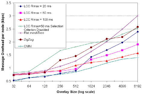
shows the average overhead per node when varying the overlay size. Control overhead of LCC is lower than those of Flat MeshTree and ZigZag, and is comparable to OMNI. We note that the per node overhead in LCC, for different values, is steady for small overlays. The maximum value reached for a 512 nodes overlay is 1.10 kbps for LCC with = 100ms, and control messages incur less than 2 kbps message overhead, in a 8000-nodes overlay. OMNI nodes obtain lower control overhead. Since it is the application-level multicast servers that are in charge of managing the delivery tree, nodes in OMNI exchange a minimum number of control messages to join the overlay. We note that the above results include overheads due to network measurement, in particular during the locating process, as we consider these results from the instant the node contacts the Rendezvous Point.
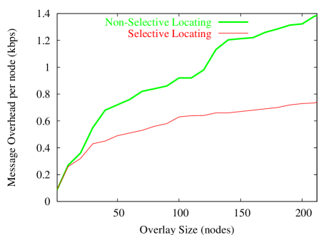
To evaluate the cost of locating the closest cluster to join, we measured on the PlanetLab testbed the average control traffic overhead (in kbps) generated during overlay joining for both the non-selective and selective locating process. We observe in Fig. 4 the importance of the selection criterion during the locating process. The per node overhead in the selective locating process is reasonably small with about 0.7 Kbps for a 212 nodes overlay. In addition, it increases very slowly with the number of members. The locating messages are roughly 50% less frequent than those of a non-selective localization. Not selecting nodes boosts the message overhead due to useless measurement operations. In this case, requested nodes would contact all the nodes in the newcomer’s level and the adjacent levels. These queried nodes will also measure their distance to the newcomer, which would incrementally add network overhead. However, we note that the selective locating process may require more time to locate the newcomer. In fact, by selecting representative nodes, the newcomer may need to contact more requested nodes than the non-selective process as discussed later and shown in Fig. 13.
VI-B2 Link adjustment rate
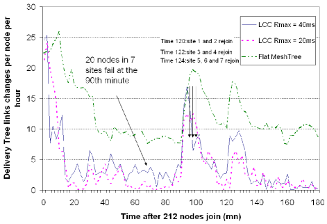
Fig. 5 shows the LCC structure stability during membership changes. On the PlanetLab testbed, we start tracking the link adjustment counts right after the last node joined the overlay. Results are collected at 30-second intervals. We observe that the link adjustment rate mostly falls below 5 per hour per node for the LCC overlay, whereas it stabilizes at roughly 10 per node per hour for the Flat MeshTree. To confirm that the LCC efficiency is robust, in case of membership frequent changes and crash scenarios, we inject a simultaneous 20-nodes failure in 7 different sites at the minute and we let them rejoin the overlay at the minute. We observe that the link adjustment activity for LCC is moderate (mostly under 5 per hour per node) during the membership changes. After the minute, the average link adjustment count falls around 2 per hour per node. Due to randomness in initially connecting newcomers to the clusters, the link adjustment rate of MeshTree is maintained at 10. This assesses our intuition that non-initially locating schemes may require high control messages for quality maintenance and structure repairs operations.
The simulation results shown in Fig. 6
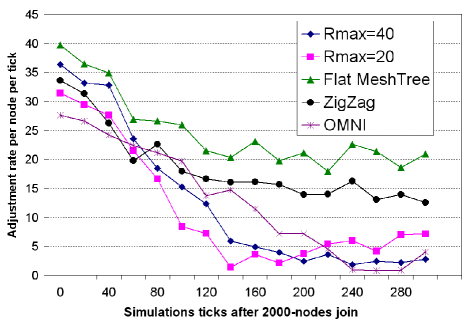
confirm the PlanetLab experiments conclusions. Flat MeshTree suffers from high adjustment rate, almost more than 20 links change per node per simulation tick. Compared to ZigZag, the LCC structure has a very low adjustment rate. This rate is stabilized at less than 5 adjustments per node per tick. Link changes in OMNI are less frequent than other improvement-based overlay structures. OMNI nodes achieve an average link adjustment per node per tick of 12.9, with a minimum of 0.78. Nodes in LCC ( = 20 ms) have an average of 11.4 adjustments per node per tick with a minimum links change of 1.4.
VI-B3 Convergence Time
The refinement-based approaches depend on the choice of a refinement period, say . A small value reduces the convergence time, as more adjustment procedures are processed within a short time, but may induce high overhead. A large may reduce overhead at the expense of increased convergence time. In the following experiments, we set the improvement period to 30 seconds, for each receiver, and study the convergence time metric which describes the overlay structure evolution in time. Fig. 7 illustrates the convergence time, showing versus the multicast session time in both simulations (Overlay size = 2000 nodes) and PlanetLab testbed. All nodes join the overlay within the first 100 seconds.
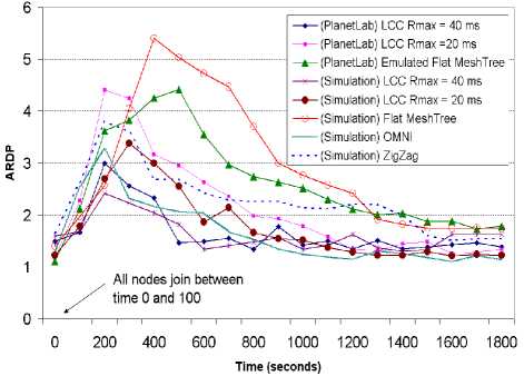
We observe that in LCC, rapidly decreases to a value less than 2 after the first 400 seconds, i.e. less than 14 improvement rounds per node. For Flat MeshTree, it takes much more time for to stabilize with almost 1300 seconds. This shows the importance of pro-actively organizing the overlay, to converge very quickly to an efficient structure. The ZigZag overlay reaches an acceptable value much more quickly than MeshTree. Although stabilized, this value is more than 2, which is still inefficient to consider the overlay converged. The convergence time of ZigZag is around 1400 seconds when falls under 2. The reason why ZigZag does not converge quickly is that during overlay growth, several group merges and splits are imposed to not exceed the maximal group size. This may induce several improvements rounds, and link adjustments. The OMNI server-based structure is not affected by frequent membership changes and converges quickly, similarly to LCC.
VI-B4 The Average incurred delay
We characterize the average incurred delay observed by the receivers in a large populated overlay by observing the variation according to the overlay size in Fig. 8.
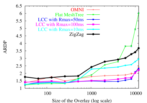
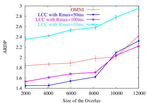
In Flat MeshTree, the increases drastically to more than 4 demonstrating that this protocol does not scale to a few thousands of nodes. Nevertheless, we note that Flat MeshTree has lower than LCC structures in small groups (overlay size 500 nodes). ZigZag maintains a stable value while the overlay size is increasing but suffers relatively poor performance with 2.5 in a 3000-nodes overlay. To make it easier to read, we zoom in on a portion of the graph in Fig. 9. We observe that the of LCC is about 60% of ZigZag. For =50 ms and 100 ms, values of LCC are roughly maintained at values between 1.4 and 2 for large overlays. OMNI has almost a constant value (1.82) and performs on average better than LCC in 12000-nodes overlay. We also note that in large overlays, for clusters defined with 10 ms as node’s scope, increases to reach 3, as nodes are more likely to be scattered. Larger scopes are more efficient in this case.
VI-B5 Stress
Fig. 10
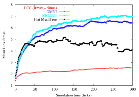
shows average physical network stress for each of the overlays, namely OMNI, ZigZag, Flat MeshTree and LCC () 2000 seconds after the last node joined. OMNI and ZIGZAG stress values stabilize between 6.5 and 7. The Flat MeshTree overlay leads to somewhat lower stress than OMNI and ZIGZAG with stress highly oscillating between 4 and 5 due to random connections established by newcomers. We note finally that LCC has an impressively low stress, 2 to 3 times less than other overlays, with a steady stress value between 2.5 and 2.8. Topology information is of paramount importance in this observation, as packets sent through the top-level hierarchy are sent to the cluster leader and in some cases to potential edge nodes. Our clustering process allows then to reduce the amount of redundant flows entering each network, considering clusters as “local networks”, and cluster leaders as “multicast-enabled routers”.
VI-B6 Robustness
When a non-leaf node quits, the overlay needs to be reconstructed. So, it is important that this node’s children can quickly locate a new parent to resume the session. In addition, the recovery process should not result in a fan-out violation in any node. In LCC, to recover from the failure of its neighbor a node has to redirect packet requests from that neighbor to another nearby in its proper cluster. We compare LCC to the grandparent recovery scheme studied in [18]. In this scheme, the children of the node which departs try first to attach to their grandparent provided that the latter has enough capacity. Otherwise, they are redirected to its descendants. We instruct a number of randomly selected nodes in a 5000-nodes overlay to leave the session simultaneously. Then, we observe the recovery time of members, as the average time for an affected node to resume the session. Results in Fig. 11
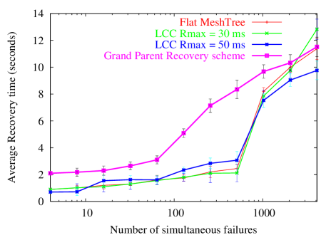
show that LCC always yields a smaller recovery time than the tree-based grandparent recovery scheme. On average, LCC takes 3.85 seconds to recover from failures, which is about 35% less than for the grand-parent recovery scheme.
In Fig. 12,
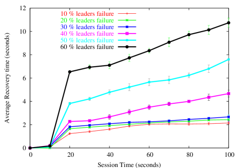
we study the capacity of the LCC overlay to recover from cluster leader failures. Each 10 seconds, a set of randomly selected cluster leaders are instructed to simultaneously leave a 5000-nodes LCC overlay ( = 50 ms). We observe that when 30% of cluster leaders fail simultaneously, the recovery time is almost 2 seconds. LCC is robust thanks to: 1) the proactive rescue plan of leaders election and 2) the edge nodes connected to the top-level topology, that allows to achieve data in case of leaders’ data disruption.
VI-B7 The locating process efficiency
To evaluate the behavior of newcomers during the locating process, we observe the average number of requested nodes contacted by a newcomer. Fig. 13 depicts the average number of requested nodes versus the total number of known cluster leaders in each requested node’s locating system. The figure plots both PlanetLab results and simulations of 200 newcomers running the selective locating process, once the overlay size reaches respectively 2000, 3000 and 4000 nodes, resp. denoted by Ov = 2000, Ov = 3000 and Ov = 4000 in Fig. 13.
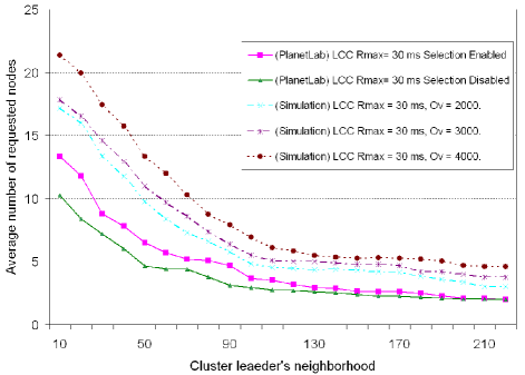
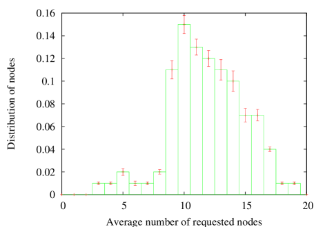
We expected that the selective locating process needs more requested nodes than the non selective process. Indeed, since it queried representative nodes at each iteration, it may be less accurate in one iteration, and hence requires to contact more nodes afterwards. Results show however, that the selection has little impact on the locating efficiency. The selective locating process performs almost as well as the non-selective process, with a maximum of 13 requested nodes in PlanetLab experimentations. Moreover, curves are very close when the number of known cluster leaders is large. We also observe that the locating process scales well to large overlays: In a 4000-nodes overlay, newcomers are located by contacting less than 12 requested nodes that know about only 60 nodes in their locating system. The distribution of nodes depicted in Fig. 14 shows that more than 80% of a 2000-nodes overlay are able to terminate the locating process by contacting less than 15 requested nodes. On average the locating time in the experiment is very low with a mean locating time of 3.2 seconds, a maximum of 7.2 seconds and minimum of 1.8 seconds. Finally, we note that 98.4% of newcomers are able to connect to their closest cluster upon their arrival. 300 seconds after the last node joins the overlay, 99.3% of nodes are connected to their closest node. This demonstrates the locating process accuracy, which is one of the reasons for the resulting promising performances of LCC.
VII Conclusion
In this paper, we proposed a practical solution to enhance different QoS aspects of overlays, namely scalability and efficiency. The overlay construction is initiated by a simple and scalable locating process that allows newcomers, after contacting a few nodes, to locate the closest cluster in the overlay. The locating process includes a selection algorithm to minimize measurement overhead. On the basis of the locating process, we proposed an hierarchical topology-aware overlay construction. We introduced mechanisms to pro-actively deal with leaders failures and underlying topology characteristics changes. Our PlanetLab and simulations experiments prove that LCC incur low overhead during both localization and data distribution. Compared to other enhancement-based and topology-aware approaches, LCC achieves shorter convergence time and performs less link adjustments rate. At the same time, the scheme is robust to nodes’ failures and performs well in terms of data distribution efficiency especially in large overlays. In conclusion, we believe that LCC is very suitable for large-scale applications such as event broadcast for thousands of attendees. In future works, we will focus on ways to automatically tune different parameters such as nodes’ scope and stop criterion, through real-life tests. We will also investigate techniques to secure the overlay and detect/prevent users from cheating.
References
- [1] Y. H. Chu, S. G. Rao, and H. Zhang, A case for end system multicast. In ACM SIGMETRICS, Santa Clara, June 2000.
- [2] D. A. Helder and S. Jamin, End-host multicast communication using switch-trees protocols. In GP2PC, Berlin, May 2002.
- [3] Z. Li and P. Mohapatra, Hostcast: A new overlay multicast protocol. In IEEE ICC, Anchorage (Alaska), June 2003.
- [4] S. W. Tan, A. G. Waters, and J. Crawford, Meshtree: A Delay optimised Overlay Multicast Tree Building Protocol. Tech. Report 5-05, U. of Kent, April 2005.
- [5] S. Banerjee, et al., Construction of an Efficient Overlay Multicast Infrastructure for Real-time Applications. In IEEE Infocom, San Francisco, March 2003.
- [6] L. Lao, et al., TOMA: A Viable Solution for Large-Scale Multicast Service Support. In IFIP Networking, Waterloo Ontario, May 2005.
- [7] D. Tran, K. Hua, and T. Do, Zigzag: An Efficient Peer-to-Peer Scheme for Media Streaming. In IEEE Infocom, San Francisco, March 2003.
- [8] S. Banerjee, B. Bhattacharjee, and C. Kommareddy, Scalable Application Layer Multicast. In ACM SIGCOMM, Pittsburgh, August 2002.
- [9] J. K. Sollins, Exploiting Autonomous System Information in Structured Peer-to-Peer Networks. In ICCCN, Chicago, October 2004.
- [10] M. Kwon and S. Fahmy, Topology-aware overlay networks for group communication. In NOSSDAV, Miami Beach (Florida), May 2002.
- [11] S. Ratnasamy, et al., Topologically-Aware Overlay Construction and Server Selection. In IEEE Infocom, New York, June 2002.
- [12] B. Wong, A. Slivkins and E. G. Sirer, A Lightweight Approach to Network Positioning without Virtual Coordinates. In ACM SIGCOMM, Philadelphia, August 2005.
- [13] http://www.planetLab.org
- [14] A. Medina, et al., BRITE: Universal topology generation from a user’s perspective. Tech. Report TR-2001-003, Boston, January 2001.
- [15] S. Saroiu, P. K. Gummadi, and S. D. Gribble, A measurement study of peer-to-peer file sharing systems. In MMCN, San Jose (California), January 2002.
- [16] http://www-sop.inria.fr/planete/software/LCC
- [17] K. Shen, Structure Management for Scalable Overlay Service Construction. In USENIX NSDI, San Francisco, March 2004.
- [18] M. Yang and Z. Fei, proactive approach to reconstructing overlay multicast trees. In IEEE Infocom, Honk kong, March 2004.