Architectural Considerations for a Self-Configuring Routing Scheme for Spontaneous Networks
Abstract
Decoupling the permanent identifier of a node from the node’s topology-dependent address is a promising approach toward completely scalable self-organizing networks. A group of proposals that have adopted such an approach use the same structure to: address nodes, perform routing, and implement location service. In this way, the consistency of the routing protocol relies on the coherent sharing of the addressing space among all nodes in the network. Such proposals use a logical tree-like structure where routes in this space correspond to routes in the physical level. The advantage of tree-like spaces is that it allows for simple address assignment and management. Nevertheless, it has low route selection flexibility, which results in low routing performance and poor resilience to failures. In this paper, we propose to increase the number of paths using incomplete hypercubes. The design of more complex structures, like multi-dimensional Cartesian spaces, improves the resilience and routing performance due to the flexibility in route selection. We present a framework for using hypercubes to implement indirect routing. This framework allows to give a solution adapted to the dynamics of the network, providing a proactive and reactive routing protocols, our major contributions. We show that, contrary to traditional approaches, our proposal supports more dynamic networks and is more robust to node failures.
Index Terms:
Self-organizing networks, indirect routing, distributed hash tables, hypercubes.I Introduction
A scalable location (lookup) service is one of the main design blocks of a completely self-organizing architecture for spontaneous networks. In traditional wired networks, location information can be easily embedded into the topological-dependent node address, which also uniquely identifies the node in the network. In self-organizing networks, however, a source only knows the destination’s identifier, and this identifier does not give any clue of the destination’s address. There is no static relation between the node’s location and the node’s identifier as a consequence of the spontaneity and adaptability of the network.
In response to these requirements, distributed hash tables (DHT) can be adopted as a scalable substrate to provide location-independent node identification [1, 2, 3, 4, 5, 6]. The functionalities of decoupling identification from location, and of providing a general mapping between them, have made the DHT abstraction an interesting principle to be integrated at network layer. Thus, indirect routing systems that offers a powerful and flexible rendezvous-based communication abstraction [4, 5, 6, 7, 8, 9] can be implemented.
A number of works have already proposed to use DHTs in routing protocols. These works can be classified in two main groups, which differ in the way the DHT structure is deployed [10]. In the first group, the addressing and the lookup models are completely independent and routing is performed at the designed addressing structure. A DHT structure is defined to distribute and locate information among the nodes in the addressing structure. Examples of proposals in the literature that implement this approach are: Terminodes [4, 11, 12], Grid [5, 13], and DLM [6]. Most of them assume, however, that nodes know their geographic coordinates through some positioning system (e.g., GPS). In the second group classification, the same structure deployed to address nodes and consequently to perform routing, is also used by the lookup model. This model describes a coherent sharing of the addressing space among the nodes, which determines the consistency of the routing protocol. Tribe [9], PeerNet [8, 14], Landmark [15, 16], and L+ [7] are examples of such protocols.
The proposals that fall in the second group proved that it is possible to build a logical and mathematical structure from mere connectivity between nodes. Routing using this mathematical space gives the exact behavior of the routing mechanism in the physical layer. Nevertheless, they lack of robustness since their space sharing mechanism follows a tree structure. Although simple to implement, a tree offers low flexibility in route selection. Furthermore, tree structures are not robust to node mobility, since a node departure causes the breakage of the tree.
Motivated by these observations, in this paper, we propose to use incomplete hypercubes instead of trees. Contrary to trees, hypercubes allow the establishment of multiple paths between any two nodes, which increases the robustness of the topology to mobility. Indeed, according its literal concept, a tree not allows nodes, in its subtree, to be connected to nodes in others subtrees. Moreover, a tree is a -dimensional structure. Otherwise, in a hypercube nodes can communicate in a -dimensional space, which allows multiple paths among nodes. We expect then to represent at least a part of the broadcast nature of wireless scenarios through the multiple dimensions of a hypercube. In wireless environments, the connectivity is controlled by the density and communication range of nodes, which can be relatively large.
Our contributions are twofold. First, we propose a proactive routing approach, where routes are determined a priori. Second, we propose a reactive protocol that establishes routes on an on demand basis. While the proactive approach is more adapted to quasi static networks, the reactive protocol is indicated to mobile networks. We show through a number of examples that our proposals are promising and are more robust to dynamic networks than the existent related tree-like approaches.
The remainder of the paper is organized as follows. In Section II, we present the indirect routing model approach with related work and the proposed architecture. We introduce the hypercube used as addressing space in Section III. Section IV presents our approach and discusses routing-specific issues. Some cases of study are addressed in Section V and Section VI discusses the applicability and future researches of our proposal.
II Indirect routing strategy
The indirect service model is instantiated as a rendezvous-based communication abstraction. Nodes called rendezvous nodes are responsible for storing the location information of others nodes in the topology. Routing is performed indirectly and the rendezvous nodes translate a node’s identifier into its location-dependent address in the topology.
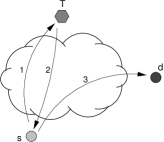
Routing is performed through a topology-dependent technique. Every node is identified by its position in the topology, which is translated into a topology-dependent address. It is important to underline that the only way of routing is by using this address. In the general case, every node has three identifiers. The first one, called universal identifier, , is supposed to be known by any other node that are supposed to communicate with the node. This identifier is independent of any network-level characteristics. It can be a word, a numerical value, or even an IP-like address. The second identifier, the virtual address , is a translation of into the virtual addressing space, . This identifier is used to name the correspondent rendezvous node. The last identifier, the relative address , is the current topology-dependent address of the node. Observe that the relative address changes if the node moves, but both the universal and virtual identifiers remain unchanged. Fig. 1 illustrates the steps of the routing procedure and the use of the described identifiers.
When source wants to communicate with destination and has no idea of ’s relative address, it first contacts the node responsible for storing the relative address of node (arrow 1). Call this node . Thus, the message sent by will travel in the network until it is received by . Note that node does not know , but it knows (obtained from ). Node knows the relative address because node has previously informed about its current address. The rendezvous node plays the role of a “rendezvous” point where the location of node is stored. The particularity of this approach is that the rendezvous point is virtually identified and can be any physical node in the network. Rendezvous nodes are distributed and depend only on the nodes’ identifiers. When contacted by , responds with a message containing the relative address of node , (arrow 2). Node can now communicate directly with (arrow 3).
II-A Related work
In the traditional Internet model, routing information is embedded into the topological-dependent node address, i.e. IP addresses have been defined for both identifying and locating a node in the network. This does not work well in mobile networks (even if they are not self-organized networks), because permanent node addresses cannot include dynamic location information, which invalidates topology information. More recently, a number of flooding-based protocols have been used to address this problem in the specific case of ad hoc networks. Nevertheless, it has been observed that these architectures do not scale well beyond a few hundred nodes [17, 18]. For instance, in sensor or wireless mesh networks, where the potential number of addressable nodes may be in the order of thousands, current solutions cannot be used.
Most proposed routing algorithms for self-organizing networks distribute the topology information to all nodes in the network. Thus, following the idea of indirection routing, the i3 [19] proposes an overlays-based infrastructure that offers a rendezvous based communication abstraction. i3 decouples the act of sending from the act of receiving: sources send packets to a logical identifier and receives express interest in packets sent to this identifier. i3 uses a set of servers that store identifiers and map packets with these identifiers to i3 nodes interested in receiving the packets. This approach combines the generality of IP-layer solutions with the versatility of overlay solutions. Our proposition uses a similar concept of indirect routing, however, it is not based in an overlay infrastructure and is independent of IP-layer.
L+ [7] proposes an improved version of Landmark [15, 16] routing, which is better suited to large ad hoc wireless networks. This protocol describes a more scalable address lookup service and algorithm improvements that react better to node mobility. An L+ node updates one location server for each level in the landmark hierarchy. L+ uses a routing algorithm similar to DSDV [20] and keeps more than just the shortest route to each destination. Nevertheless, L+ and Landmark creates a tree-based hierarchical topology where nodes are placed, offering a low flexibility in route selection.
Tribe [9] is a rendezvous-based routing protocol for self-organizing networks. By managing regions of a logical addressing space, Tribe nodes route in a hop-by-hop basis with small amount of information and communication cost. Nodes that are physically close in the network also manage close regions in the Tribe addressing space. Thus, the main component of Tribe is its proposed simple manageable addressing space used to assign addresses to nodes. Nevertheless, this space is also a tree-like structure, which limits paths by the hierarchical structure of a tree – there is only one path between any two nodes.
Similarly to Tribe, PeerNet [14] is a peer-to-peer based network layer for dynamic and large networks. The address reflects the node’s location in the network and is registered with the respective identifier in the distributed node lookup service. In PeerNet, the addresses are organized as leaves of a binary tree – the address tree. PeerNet routing is a recursive procedure descending through the address tree. Thus, in contrast to Tribe, PeerNet routing disseminates information about the global state of the network, and nodes maintain a routing table that has entries, i.e. per-node state (where is a number of nodes in the network). Because of the address tree organization, a node movement may require the assignment of new addresses to several nodes in PeerNet infrastructure, which implicitly generates many updates in lookup entries.
II-B Increasing the number of paths connections
The design of a self-organized network architecture requires an efficient combination of robustness and complexity. The resilience of existent proposals and, consequently, the performance of the routing protocols are strongly related to the complexity of the deployed addressing structure. On the one hand, tree-like structures (e.g., L+ [7], Tribe [9], and PeerNet [8]) lead to simple manageable spaces. Nevertheless, they have low route selection flexibility, which results in low routing performance and poor resilience to failures/mobility. Their low complexity is obtained at the cost of some loss of robustness. On the other hand, more complex structures, like multidimensional Cartesian spaces, improve the resilience and routing performance due to the flexibility in route selection. The associated addressing and location models, however, become more complex and require a tight association between the logical and physical planes. In this paper, we propose to increase the number of paths connections through hypercubes.
Hypercubes have the inherent property of multiple paths between any couple of nodes, given a good and interesting logical-topological mapping. This possibility gives the following improvements. First, traffic can be well balanced, in contrast to what occurs in a tree, where the root is heavily charged. This characteristic allows to use more efficiently the bandwidth. Another important improvement is that distances in a network are closer to real distances, which is not necessarily true in a tree. This makes communications shorter. Finally, a hypercube allows to use different routing methods thanks to its logical-topological mapping (proactive and reactive routing), i.e. the network could have a routing schema adapted to the dynamics of the network.
In the following sections, we present our addressing system and explain how hypercube representation allows the specification of a logical structure where proactive/reactive routing approaches can be exploited while the lookup service is performed in a simple way.
III Address Spaces based on hypercubes
In this section, we describe how to implement a virtual addressing space based on a hypercube structure.
III-A A very brief overview of hypercubes
The hypercube is a generalization of a 3-dimensional cube to an arbitrary number of dimensions . Each node of the -hypercube has coordinates 0 or 1 for each dimension, covering all the combinations. This implies that the total number of nodes is . Each node is linked to all nodes whose coordinates differ only in one dimension. For example, the cube has a node at coordinates (), or simply 000, which is connected with nodes at coordinates 001, 010 and 100, because all these nodes differ only in one of their dimensions. Thus, the degree, i.e. the number of edges, of each node equals the dimension .
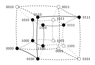
The most important property of the hypercube is the adjacency of nodes generated by its construction. Fig. 2 displays a hypercube of dimension 4. We can use the coordinates of a node as its network address, then the length of the address is . It easy to see that the distance between two nodes is measured by XORing the two addresses. For example, the distance between nodes 0100 and 0111 is 2, because there are two different bits between these nodes, e.g., a route could be 0100 -> 0110 -> 0111.
III-B The network layer
Using node coordinates in the hypercube as its relative address , it is possible to map a physical network into a logical one. For an arbitrary physical network, the corresponding mapping produces an incomplete hypercube, because the number of nodes present is less than , and their physical connection possibilities do not necessarily correspond to all edges of the hypercube. We display an arbitrary network in Fig. 3 and its representation on the hypercube in Fig. 2, where present nodes are filled in black. Fig. 3 also has the routing tables at the right side of the node, which will be treated latter.
Considering nodes in Fig. 3 have a circular coverage radius, then some nodes use fewer than their possible physical connections. For example, node 0100 has a physical connection with node 1010, but their addresses differ in more than one bit and they are not connected in the hypercube structure. We say then that the hypercube is incomplete. Nevertheless, even loosing some connections, the network can take advantage of the hypercube adjacency for routing.

One way to improve this mapping, i.e. more physical connections become edges in the hypercube, is assigning multiple addresses to some nodes. Since two nodes might not be neighbors in the hypercube although being physically connected, this allows us to better represent physical adjacencies.
Summarizing, the information stored in each node is composed of the main address, the secondary addresses and its addressing space. The main address corresponds to a network or relative address , which is given during the connection process. When a new node joins the network, the main address is selected by itself from the addresses proposed by its neighbors (already connected to the network). Before obtaining the main address, the new node could chose one or more secondary addresses, if it were connected to other physical neighbor nodes which are not adjacent in the hypercube, i.e. their network addresses are not adjacent to the new node’s main address. For example the node 0110m3 in Fig. 3, has it main address and the secondary one: 0111. This secondary address is used for connecting nodes 0110 and 1111, because 0111 is adjacent to 1111, i.e. they only differ in one bit.
Each node manages an addressing space. This addressing space is used to: store the database for address resolution queries,111The rendezvous node stores the entry. and give addresses to new nodes. The later function implies the delegation of a corresponding portion of addressing space.
The addressing space of a node is determined by its main address and a mask. This mask is represented by the number of “ones” from the left side, e.g., m3 is the mask 1110 because the address length is . The address and its mask (doing bitwise logic AND) gives the addressing space managed by the node. This method is very similar to IP subnet masks, because the part with zeros corresponds to the addressing space managed by the node. For instance, node 0000m2 in Fig. 3 manages addresses 0000 (its main address), 0010, 0001, and 0011.
The first parameter to fix is the dimension of the hypercube, which is known a priori by all the participants of the network. On the one hand, this parameter limits the maximum number of nodes, but on the other hand, gives more flexibility to connecting nodes due to secondary addresses. The problem is that each new node should be adjacent to a maximum number of nodes, ideally to all nodes within its radio coverage, in order to be strongly connected. Intuitively, the larger the addressing space, the richer the nodes’ choice. We address this issue in detail in Section V.
III-C Indirect routing in the hypercube
Recall that using an indirect routing technique means that there are two phases for forwarding information: the source asks, to the rendezvous node, the destination’s address using its universal identifier, the source sends the messages to the destination. This mechanism presupposes that there exists a method to find the rendezvous node, because the only available information is the destination’s rendezvous address which is managed by a certain node.
As previously seen, the main address and the addressing space are given by already connected nodes. When a node gives an address, it also delegates a portion of its used addressing space (generally the upper half of it) to a new incoming node. For example, in Fig. 3 the node 0000m2 would give the main address and addressing space 0010m3 to a new node, causing the change in the 0000 mask: from m2 to m3, and it sends all the address resolution information stored for this addressing space. This means that the main address of a new node is 0010, and it manage the addresses 0010 and 0011. The utilization of this method for all the nodes causes a tree distribution of the network addresses, which we call in the remainder of this paper. Fig. 3 presents a real topology, where cutting the link between nodes 0111 and 1111 we can observe an example of the tree.
Therefore, for a given rendezvous address , we should find all the possible nodes which can manage it in their addressing space. This task might be very simple using the tree. In this case, it is enough to move through the tree following the match of the rendezvous address ’s prefix. Again, this search is trivial for the complete hypercube, but in an incomplete case one needs to find the tree. In a normal operation, always exists. We handle different cases in Section V.
IV Design issues: Proactive or reactive?
We present two routing methods in this paper: proactive and reactive. The first builds and maintains the routing tables all the time, and assures a route for every node in a network. The second method finds a route on demand, and maintains the route for a given period of time. Clearly, the proactive approach is very useful for quite stable networks, (i.e. where node mobility is low and nodes’ lifetime is long). For highly dynamic networks, where nodes are joining and leaving all the time, the reactive method is more appropriate.
IV-A Case 1: Proactive routing protocol
In a complete hypercube, there is no problem for routing, because all nodes and edges exist, then it is possible to use the adjacency properties of the hypercube. In a general case, we should propose a routing table composed of a combination of default entries and some other routing entries. The default entries take advantage of the address assignment method (the tree). The other entries consist in a set of routes for other connections which do not belong to , represented by the secondary addresses. In other words, we put one entry in a routing table for each connection of the node, and also for the shortest advised routes. Because the address assignment method, each node has a parent node and it may also has some children nodes, noted by
-
•
Parent node: is the node that assigns a main address to node . The parent node also delegates a portion of its addressing space to node .
-
•
Child node: is the node that has node as parent node, i.e. , , being the number of children nodes.
-
•
Children set: represented by , is the set of children nodes.
The address assignment method is formalized as follows. The main address of node is m, where is the prefix of the address, is the zeros which completes the address length, and is the number of bits from the left. The prefix is obtained by doing , where . Thus, the node assigns an address as following
| (1) |
The parent node has always the main address , where is the first value of , i.e. when the main address of was assigned. Each child in the children set , when they exist, has as main address . Note that the child index is defined as .
Each entry in a routing table is composed of a prefix, a mask, and a next hop. The masks have the same form as in the IP case, i.e. the number of ones from the left side.
As mentioned before, there are two types of entries:
-
•
the entries of tree, e.g., for the parent node , and for each child node ;
-
•
the entries for a neighbor (i.e. , , and in the example) which does not belong to the tree is , where is the prefix obtained applying the mask defined by , as .
The entries at ’s routing table are
| ⋮ | ⋮ | ⋮ | |
|---|---|---|---|
where , and is the number of bits from the left, obtained after the child ( and ). The order is very important because the first matching is used for routing.
These entries are determined by Algorithm IV-A when a local node is connected to . The first step computes the node which is in the middle of the path from to in the tree . Then, it computes , which is the length of the matching prefix, either of or of , because is ancestor o or . Finally, a message advertising the new route is sent to all neighbors. Then, once receiving the message each neighbor executes the Algorithm IV-A to add and resend the new received routes when necessary. In this algorithm, is the distance in the hypercube.
Algorithm 0.1 Routing tables construction at node
-
1
Reach a node , such that , where is the distance on the default tree .
-
2
Set the entry in ’s routing table, where is the number of unchanged bits between and, if it is a ’s descendant in a , else is a ’s descendant.
-
3
Send a message to all neighbors, except , with .
Algorithm 0.2 Forwarding routing tables messages
-
1
Node receives from neighbor
-
2
If the then
-
3
Add the entry
-
4
Send a message to all the neighbors, except , with .
-
3
We should consider also the case when a node lost the connection with its parent node . In this case it sends a message to its neighbors, in order to find a connection with the tree. This message is resent by each node until one, e.g. , which is connected to its parent node and the prefix of the first node is not contained in . Then, node resends a message reply to which confirms and sets the default route of : , such as is the ’s neighbor having a path to . The node also sends a message, following the tree, to reach or its closer ancestor, we call this node . The objective is to establish a route from to passing by , restoring the tree. In this way the tree is reconnected, assuring the default route for nodes and .
IV-B Case 2: Reactive routing protocol
In our case, the logical topology is built following adjacent addresses, hence there is a coherent mapping between the physical positions and the logical addresses.
There are two complementary methods for routing: the first is for address resolution messages and the second is for other messages.
Let us begin with the second case. This method considers that the hypercube is complete, and routes the message by sending it to neighbors whose addresses are closer to the destination. When a message is blocked, i.e. there is no route, the message goes backwards and it is sent through a different route, leaving a mark on the unsuccessful route. Algorithm IV-B presents the method used to forward a message at node , received of node , when the source is and the destination is . Fig. 4 shows an example where there is no route from to . The number over the arrows corresponds to step number of the algorithm. The curved arrows are the sent message and the right arrows is the return of the message . The special case of arrows with and correspond to the first and second iteration of the loop, respectively.

Algorithm 0.3 Forwarding in reactive routing at node
-
1
receives a message form neighbor .
-
2
sends the message to a neighbor , such that minimizes
-
3
If there is no route from then mark this route and resend the message to other neighbor .
-
4
If the message is returned again then send the message to its parent in and mark all the remaining neighbors as unexplored.
-
5
If the message returns then do
-
until all neighbors are explored:
-
6
send the message to a neighbor marked as unexplored
-
7
if the message returns then mark this neighbor as blocked, and return to step 5.
-
6
-
-
8
If there is no route then
-
9
If the original sender is the local node :
-
10
then .
-
11
else resend the message to the neighbor sender .
-
10
-
9
Remember that is the distance in the hypercube, and is the initial tree used for distributing the addressing space. This algorithm favors the exploration of farther regions from the root of . If it does not find a route then it sends the message towards the root, and finally if it still does not find a route, it performs an exhaustive exploration. A timer is used by resetting the marks in unsuccessful routes, but they can also reset by an update message. The value of this timer is long, and is only used to give a robust behavior, i.e. when an update message is lost.
The update messages are sent when new topological connections are made. When a node has been connected with another node , node sends update messages with its address and the new neighbor address to all its neighbors ( does not consider this message). Other case is when receives an update message from a neighbor , then clears the blocked routes in the corresponding interface.
The first routing case, which corresponds to a resolution request, uses a variation of Algorithm IV-B. This variation consist in, firstly to change of step 2, and secondly to eliminate the step 3. The elimination of step 3 is motivated to give more priority, to address resolution messages, to reach their destination. It is clear that the number of address resolution messages 222Discovered addresses are stored in a local cache table and associated to a timeout. Resolution messages are sent one time for the first communication, and then, when the timeout of the corresponding cache table’s entry has expired. are lower than the data messages, and then they have less contribution to the congestion of the ’s root. The step 2 of Algorithm IV-B is replaced by
| 2 | sends the message to a neighbor , such that |
|---|---|
| minimizes . |
That is, it finds the neighbor which minimizes the distant to one of the possible prefixes of the virtual address in the tree. The reason is that the virtual address is contained in the managed addressing space of a certain node, because the tree distribution method.
V Practical considerations and case studies
In this section we will consider the application of our architecture in different scenarios. Then, we present two examples for each routing method.
V-A Choosing the dimension
One important issue of hypercubes is the addressing space, because it defines multiple possibilities of connection and routing. We consider two cases: sparse and dense networks. Given a fixed , nodes are connected until their radio neighbors have not any available addresses. In sparse case, nodes are mainly connected augmenting the diameter of the logical graph. Dense networks, however, are susceptible to have a lot of connections per node, increasing the number of secondary addresses, consuming a lot of address per node, and given a small diameter of the logical graph. Therefore, there is a trade-off between the radio coverage and the maximum size of the network for choosing the dimension.
More precisely, the extreme case on sparse network is when a node has only two neighbors, this results in a linear chain with nodes because the address distribution method follows a tree. In general, the maximum number of nodes that can join a sparse network with neighbors is
where is the dimension of the hypercube, and is the following recursive function
For dense networks, the number of addresses in each node depends on the number of physical neighbors, considering that all nodes could be obtained from a compatible secondary address with their neighbors. Therefore, a high percentage of neighbors of a node are connected among them, which means that the network has a lot of triangles. If the percentage is denoted by , is the number of neighbors, and is the number of dimensions, then, for each nodes there is a clique333In a clique of nodes each node is connected to all nodes, and the total number of connections is .. Consequently, if is the number of nodes that can join a dense network, there are cliques and number of connections , i.e. secondary addresses, for each clique. Then,
where is the total number of nodes in a -dimensional hypercube.
A useful approximation of maximum path length, for both cases, is the following. Considering the number of total neighbors up-to distance for a node in a regular network (i.e., each node has neighbors). Then, for we have , because the neighbors at distance are , and each of these neighbors has other different neighbors. The maximum path length for a network with nodes is
which is valid for . The main difference of between sparse and dense networks is the value of , because dense networks has a higher than sparse ones, thus the maximum path distance will be smaller in dense networks.
Therefore, considering the general purpose case, where the addresses are not too long and where it is also possible to obtain some secondary addresses, an empirical choice of could be . That is, we propose to increase the addressing space by 20% of the address length, allowing up to secondary addresses per node.
V-B An example of the proactive protocol
We present here examples of the routing table construction, communication between two nodes, and address resolution.
For the proactive method, each node has a pre-established table. Consider Fig. 3 and the routing table of node 1000m3:
| destination | next hop |
|---|---|
| 1010/3 | -> 1010 |
| 1100/2 | -> 1100 |
| 0000/0 | -> 0000 |
The first entry means that all messages addressed to destinations whose most significant bits are 101 must be sent through node 1010 (one of its children). The second line is for addresses attained through the child 1100. It is worth noting here the strict relationship between the addressing space of a child and the destination entry in the table at the time the child was connected, e.g., the entry 1100/2 and its first child 1100m2. Currently, node 1100 has mask m3 because it has already assigned an address to a new node (but its mask was m2 before the arrival of the new node). We call the addressing space of a node at the time it joins the network the initial addressing space of the node.
Finally, the last line is the default route to its parent node 0000. (Note that “/0” means the first “0” most significant bits.) The default route is represented by 0000/0 because it matches all nodes.
It is important to stress that the order of the lines in the routing table is important. The first line is the most constraining entry, because the 3rd most significant bits must match (due to “/3”). The last line is the least constraining entry, hence, the default route entry. The first node in the network does not have a default route, because it has no parent and it is the parent of all nodes. However, it has entries for its children, then all the possible addresses in the hypercube are represented.
There are others types of entries in order to represent a connection that does not follow the tree structure. This is the goal of our proposal. For example, Fig. 3 displays the connection between nodes 1111 and 0111, and the corresponding routing tables. In this scenario, node 1111 has the following routing table:
| destination | next hop |
|---|---|
| 0000/1 | -> 0111 |
| 0000/0 | -> 1110 |
The default route is through the node’s parent, and the other route means that all the addresses whose most significant bit is 0 can be reached through node 0111. This entry, at local node 1111, can be determined by Algorithm IV-A after the connection with 0111.
Now we illustrate a case where a node exchanges data. Consider that node 1110 sends a message to node 0110. The first entry in the routing table of 1110 is 1111/4 ->1111. This means that the comparison is done using the four most significant bits (because of “/4”) of the destination node 0110. We observe that the final destination is different to the entry at routing table, i.e. 01101111, and therefore the matching fails. The second line is 0100/2 ->1111, the two most significant bits of the destination are 01, and they equal the two most significant bits of 0100/2. Therefore, this entry matches and the packet is forwarded to node 1111. The first entry of the routing table of 1111 is 0000/1 ->0111 and the most significant bit of destination is 0 – this entry matches and the packet is forwarded to 0111. As 0111 is a secondary address, the packet is now at node 0110, which is the final destination address.
Finally, we present an address resolution request. This kind of message is routed in the same form as data messages. The only difference is that the destination, i.e. the rendezvous address, may or may not be the main address of a node. If it is not the main address, the message will arrive at the node which manages this address. Therefore, before applying the routing algorithm, each node must verify if the destination belongs to addresses that it manages. For example, node 0110 wants to know which is the network address of a particular identifier . Then it applies the hash function to know the rendezvous address, that is 1101. Because this address is not managed by the local node 0110m3, it sends the message to 1101. The first entry in 0110’s routing table is 1100/2 ->1111, and it matches because the two most significant bits of 1101 are 11. Then the request message is sent to node 1111. This node does not manage the address in the request either, so it forwards the message using its routing table. The first entry is 0000/1 ->0111, which does not match. The second is 0000/0 ->1110, which matches because it is the default routing entry, and the message is forwarded to node 1110. Since this node has a m4 mask, it does not manage the address into the request, so it will forward the message. The first entry in its routing table is 1111/4 ->1111, which does not match, and the second one is 0100/2 ->1111 which does not match either. Finally, the last entry matches because it is the default route. The node 1100 receives the request for the server resolution of address 1101, and the addresses managed by 1100m3 are 1100 and 1101. This node looks up the network address corresponding to node , and sends a reply to the source node 0110 with the network address . The source can then directly communicate to the node whose address is .
V-C An example of the reactive protocol
In the reactive case, there are no routing tables, but some information concerning temporary path recently used by each node. This information is created in a communication step, storing the unsuccessful paths. In this section we present two communication cases and an address resolution procedure.
Because this method starts with no a priori knowledge of how complete the hypercube is, it uses standard routing in hypercubes. This means that routing is done by changing the different bits one by one, i.e. sending to neighbors closer to the destination (recall that a node is a neighbor if their addresses differ on one bit). For example, if node 0100 sends a message to 1111, it does (0100 XOR 1111)=1011, that is the first, third, and fourth bits change. Then node 0100 can send the message to one of the following neighbors: 1100, 0110 or 0101, because they differ, from 0100, in only one bit. The only node present in the network is 0110 (see Fig. 3), therefore the message is forwarded to this node. At node 0110, XOR is applied again, which results in 1001. The only existing neighbor is 0111, which corresponds its secondary address. Finally, the result of XOR is 0001, and the neighbor 1111 is the last step.
We illustrate a more complicated case with the following example. Node 1000 sends a message to node 0110, then (1000 XOR 0110) = 1110, and the possible forwarders in the network are 1010 and 1100. Node 1000 sends then the message through 1010. Candidate forwarder neighbors of node 1010 are 1110 and 0010, because (1010 XOR 0110) = 1100. But 0010 does not exist in the network and 1110 is not connected to it. Node 1010 sends the message backwards, and node 1000 sets a temporary entry because now it knows that there exists no path. Of course, this entry should be removed after a timeout, or if the node becomes connected to other nodes. Finally, the message is forwarded to node 1100. At this node, the result of (1100 XOR 0110) is 1010, then a possible forwarder, present in the network, is 1110. This latter receives the message and computes (1110 XOR 0110) = 1000, but the nodes 1110 and 0110 are not interconnected. In this case, it is better to take a new path in the opposite way. Then, the message is sent to node 1111. This node computes (1111 XOR 0110) = 1001, and the possible forwarder is 0111. As 0111 is a secondary address and its primary address is 0110, the message has arrived to the final destination.
For the address resolution case, we use the modified Algorithm IV-B. Suppose that node 1110 wants to send a message to node with universal address , then it obtains 0101 (the rendezvous address). The node who minimize is its parent node . Since the other nodes are in a similar situation, the message is forwarded to consecutive parent nodes until it reaches 0000. Because the first most significant bit is the same as the desired address 0101, the actual node checks if this address belongs to its managed space. The result is negative and the message is sent to the neighbor 0100 which is the closest to 0101. This node has in its managed space the addresses 0100 and 0101 (because its mask is m3). Therefore, node 0100 looks up the virtual address and sends it to 1110 in a response message. In this case, the communication was done using the tree. If the tree is disconnected, the message is sent backwards until a route is found, as in the data communication case.
VI Discussion and further research
The most effective protocol to self-organization networks is a combination of a good physical-to-logical mapping with a simple and robust routing protocol, and small routing tables. The geographical routing could be the most promising, but the reception of GPS can not be enough, e.g., inside of a building. Moreover, the GPS error, which depends also the reception quality, is too large for some dense networks. Next candidates are those that use indirect routing and build a logical and mathematical structure from mere connectivity between nodes. Up to now, this protocols propose a logical tree for connecting nodes [7, 8, 9, 14, 15, 16, 29].
In the deployment of self-organized systems, flexibility in route selection is an important issue to be considered, which affects the performance in terms of path length, traffic concentration, and resilience to failures. In this context, the organization of the addressing structure has a strong influence. In the tree-based structures, paths are limited by the hierarchical structure of a tree – there is only one path between any two nodes. A tree offers low flexibility in route selection, contrary to the greater flexibility offered by the multi-dimensional approaches. Our hypercube approach offers multiple links options that get the path closer to the physical distance.
A spontaneous network could have a well balanced traffic only when the distance between two nodes is closer to their physical distance. In a case that the logical structure is a tree, is very difficult to fill this condition, mainly because the connection order. Even, following the optimal connection order, when the density of nodes is high, a message sent to a physical neighbor should pass to other node before to arrive at the destination. Instead, the incomplete hypercube is better because it allows multiple links, even for far nodes, giving more privilege to the neighbors connections. This also makes a more coherent physical-to-logical mapping, given a similar physical and logical distances. Therefore, using the hypercube as underling logical structure, coupled with indirect routing, we provide redundant connections, a better load distribution and two different routing methods. These characteristics permit to cover a wide range of applications according to their mobility characteristics.
Although the greater flexibility in route selection offered by the multi-dimensional approaches, their associated addressing and location models are more complex, contrarily to simple manageable structures offered by tree-like structures. The main problem with the incomplete hypercubes could be their relative complexity, but evidently there exist a trade-off between the simplicity and the robustness. Our proposal provides the advantages of a good physical-to-logical mapping, and two routing protocols adapted to the mobility characteristics, given a robust behavior.
Since this paper had as objective to describe a hypercube-based architecture to implement indirect routing, future research includes a complete evaluation of the proposed protocol under fixed and mobile environments. Some optimization mechanisms and implementation issues for improving robustness in terms of location information availability, load balancing, and failures are also interesting to analyze.
References
- [1] S. Ratnasamy, P. Francis, M. Handley, R. Karp, and S. Shenker, “A scalable content-addressable network,” in Proceedings of ACM SIGCOMM’01, Aug. 2001.
- [2] I. Stoica, R. Morris, D. Liben-Nowell, D. R. Karger, M. F. Kaashoek, F. Dabek, and H. Balakrishnan, “Chord: a scalable peer-to-peer lookup protocol for internet applications,” IEEE/ACM Transactions on Networking, vol. 11, no. 1, pp. 17–32, Feb. 2003.
- [3] A. Rowstron and P. Druschel, “Pastry: Scalable, distributed object location and routing for large-scale peer-to-peer systems,” in Proceedings of IFIP/ACM Middleware’01, Nov. 2001.
- [4] L. Blazevic, L. Buttyan, S. G. S. Capkun, J. P. Hubaux, and J. Y. L. Boudec, “Self-organization in mobile ad-hoc networks: the approach of terminodes,” IEEE Computer Communications Magazine, June 2001.
- [5] J. Li, J. Jannotti, D. S. J. D. Couto, D. R. Karger, and R. Morris, “A scalable location service for geographic ad hoc routing,” in Proceedings of ACM MOBICOM’00, Aug. 2000.
- [6] Y. Xue, B. Li, and K. Nahrstedt, “A scalable location management scheme in mobile ad-hoc networks,” in Proceedings of IEEE Conference on Local Computer Networks (LCN), (Tampa, FL, USA), Nov. 2001.
- [7] B. Chen and R. Morris, “L+: Scalable landmark routing and address lookup for multi-hop wireless networks,” tech. rep., Massachusetts Institute of Technology, Cambridge, Massachusetts - MIT LCS Technical Report 837 (MIT-LCS-TR-837), Mar. 2002.
- [8] J. Eriksson, M. Faloutsos, and S. Krishnamurthy, “Scalable ad hoc routing: The case for dynamic addressing,” in Proceedings of IEEE INFOCOM’04, (Hong Kong), Mar. 2004.
- [9] A. C. Viana, M. D. Amorim, S. Fdida, and J. F. Rezende, “Indirect routing using distributed location information,” ACM Wireless Networks, vol. 10, no. 6, pp. 747–758, Dec. 2004.
- [10] A. C. Viana, M. D. Amorim, S. Fdida, and J. F. Rezende, “Self-organization in spontaneous networks: the approach of dht-based routing protocols.” to appear in Ad Hoc Networks Journal, 2005.
- [11] J. P. Hubaux, T. Gross, J. Y. L. Boudec, and M. Vetterli, “Towards self-organized mobile ad hoc networks: the terminodes project,” IEEE Communications Magazine, vol. 39, no. 1, pp. 118–124, Jan. 2001.
- [12] Terminodes Project. http://www.terminodes.com/.
- [13] Grid Project. http://www.pdos.lcs.mit.edu/grid/.
- [14] J. Eriksson, M. Faloutsos, and S. Krishnamurthy, “Peernet: Pushing peer-to-peer down the stack,” Proceedings of International Workshop on Peer-To-Peer Systems (IPTPS’03), Feb. 2003.
- [15] P. F. Tsuchiya, “The landmark hierarchy: a new hierarchy for routing in very large networks,” in Proceedings of ACM SIGCOMM’88, Aug. 1988.
- [16] P. F. Tsuchiya, “Landmark routing: Architecture, algorithms and issues,” tech. rep., MTR-87W00174, MITRE Corporation, Sept. 1987.
- [17] J. Broch, D. A. Maltz, D. B. Johnson, Y. Hu, and J. Jetcheva, “A performance comparison of multi-hop wireless ad hoc network routing protocols,” in Proceedings of ACM MOBICOM’98, Oct. 1998.
- [18] S. Ni, Y. Tseng, Y. Chen, and J. Sheu, “The broadcast storm problem in a mobile ad hoc network,” in Proceedings of ACM MOBICOM’99, pp. 152–162, Aug. 1999.
- [19] I. Stoica, D. Adkins, S. Zhuang, S. Shenker, and S. Surana, “Internet indirection infrastructure,” in Proceedings of ACM SIGCOMM’02, Aug. 2002.
- [20] C. E. Perkins and P. Bhagwat, “Highly dynamic destination sequenced distance-vector routing (dsdv) for mobile computers,” in Proceedings of ACM SIGCOMM’94, Oct. 1994.
- [21] F. T. Leighton, Introduction to parallel algorithms and architectures: array, trees, hypercubes. Morgan Kaufmann Publishers Inc. San Francisco, CA, US, 1991.
- [22] E. Oh and J. Chen, “Parallel routing in hypercube networks with faulty nodes,” in IEEE International Conference on Parallel and Distributed Systems (ICPADS ’01), pp. 338–345, July 2001.
- [23] M. Schlosser, M. Sintek, S. Decker, and W. Nejdl, “Hypercup - hypercubes, ontologies, and efficient search on peer-to-peer networks,” in Agents and Peer-to-Peer Computing: A Promising Combination of Paradigms, LNCS 2530, pp. 112–124, July 2003.
- [24] M. A. Jimenez-Montano, C. R. de la Mora-Basanez, and T. Poeschel, “On the hypercube structure of the genetic code,” in Proceedings of Bioinformatics and Genome Research, pp. 445–459, Oct. 1994.
- [25] D. Wang, “A low-cost fault-tolerant structure for the hypercube,” Journal of Supercomputing, vol. 20, no. 3, Nov. 2001.
- [26] R. Friedman, S. Manor, and K. Guo, “Scalable stability detection using logical hypercube,” tech. rep., Technion, Department of Computer Science Technical Report 0960, May 1999.
- [27] J. Slack, “Visualization of embedded binary trees in the hypercube,” tech. rep., Final Report of the Project for Information Visualization, Department of Computer Science, University of British Columbia, Apr. 2003.
- [28] Y. Saad, “Data communication in hypercubes,” tech. rep., Research Report 428, Department of Computer Science, Yale University, New Haven, CT, 1985.
- [29] A. C. Viana, M. D. Amorim, S. Fdida, and J. F. Rezende, “Indirect routing using distributed location information,” in Proceedings of IEEE International Conference on Pervasive Computing and Communications (PERCOM’03), (Dallas-Fort Worth, Texas), Mar. 2003.