EPspectra: A Formal Toolkit for Developing DSP Software Applications
Abstract
The software approach to developing Digital Signal Processing (DSP) applications brings some great features such as flexibility, re-usability of resources and easy upgrading of applications. However, it requires long and tedious tests and verification phases because of the increasing complexity of the software. This implies the need of a software programming environment capable of putting together DSP modules and providing facilities to debug, verify and validate the code. The objective of the work is to provide such facilities as simulation and verification for developing DSP software applications. This led us to develop an extension toolkit, EPspectra, built upon Pspectra, one of the first toolkits available to design basic software radio applications on standard PC workstations.
In this paper, we first present EPspectra, an Esterel-based extension of Pspectra that makes the design and implementation of portable DSP applications easier. It allows drastic reduction of testing and verification time while requiring relatively little expertise in formal verification methods. Second, we demonstrate the use of EPspectra, taking as an example the radio interface part of a GSM base station. We also present the verification procedures for the three safety properties of the implementation programs which have complex control-paths. These have to obey strict scheduling rules. In addition, EPspectra achieves the verification of the targeted application since the same model is used for the executable code generation and for the formal verification.
keywords:
real-time application, Esterel, formal verification1 Introduction
Esterel [Berry (1996)] is a synchronous programming language targeted at reactive systems. Esterel programs perform an input-driven computation: wait for inputs and compute corresponding outputs in a cyclic manner, referred to as a reaction. Esterel is also a formal language. The Esterel system allows one to provide specification, simulation, automatic code generation, and verification. Taking into account that most of traditional verification methods are concerned with proving properties only of abstracted models of programs rather than programs themselves, the Esterel methodology allows one to directly verify the actual code of Esterel programs that corresponds to the targeted implementation. It guarantees that the Esterel programs satisfy the properties to be proved on condition that all source code is correctly compiled to the targeted code.
It still holds true that the number of transistors per integrated circuit roughly doubles every 18 months according to Moore’s law111See http://www.intel.com/research/silicon/mooreslaw.htm. Thus, programming environments for Digital Signal Processing (DSP) applications may no longer be required to rely on specialized DSP hardware since the performance of general purpose processors and peripheral equipment increases along with the high-tech curves. This leads to the shift of hardware-operation functions into software. A software approach to developing DSP applications allows the following advantages: re-usability of existing hardware, ease of upgrades, and more flexible applications. Nevertheless, it makes the implementation of software applications more complex because of the need for multi-disciplinary knowledge of software architecture, signal processing, real-time scheduling, networking protocols, validation, etc. Furthermore, it requires an appropriate development environment accessible to programmers.
The goal of this work is to develop a methodology to make the implementation of DSP software applications easier by allowing the code for specification, simulation and verification to be executable. We make the best of the characteristics of Esterel, a formal as well as programming language.
We have developed an Esterel-based extension toolkit, EPspectra built upon Pspectra222It provides a signal processing programming environment to implement portable DSP applications on general-purpose workstations. See http://www.sds.lcs.mit.edu/SpectrumWare/ [Bose (1999), Vasconcellos (2000)]. In the EPspectra system, the control part of DSP application, which is to be verified eventually, is specified in Esterel and the data part, which contains DSP computation intensive modules, is specified in C/C++. The behaviors of the control part are checked out in simulation with Xes [Berry and team (1999)] and its safety properties are verified with Xeve [Bouali (1998)]. We demonstrate the verification and the implementation of an example of DSP software applications, the radio interface part of a GSM Base Transceiver Station using EPspectra. We also report the results of performance comparison between the Esterel based implementation and the generic method based one.
This paper is structured as follows: Section 2 describes the Pspectra software architecture, which is divided into a data part and a control part. It also describes an extension toolkit, EPspectra, of which the control part is re-designed and implemented in Esterel. Section 3 presents the features that are derived from the Esterel methodology and Section 4 focuses on scheduling techniques considering two models: the Data-Pull Model and Data-Reactive Model. Once the extension toolkit has been described, we present in Section 5 the implementation of a practical example which corresponds to the radio interface part of a GSM Base Transceiver Station. Three safety properties of the implementation are verified in Section 6. In Section 7, the performance results between EPspectra and Pspectra are compared in terms of the capacity of computation and the number of lines of code. Section 8 discusses the related work and the last Section concludes the paper and presents future directions.
2 Pspectra & EPspectra
Pspectra, developed by the SpectrumWare project at MIT, is a real-time signal processing programming environment used to implement portable DSP applications such as software radios on general-purpose workstations. This environment includes a library of portable (across platforms) DSP functions and an I/O subsystem. With Pspectra, the hardware part is minimal and the boundary between software and hardware is shifted right up to the A/D converter. This increases flexibility by bringing more functions under software control.
The Pspectra software architecture is partitioned into a control part (out-of-band components) and a data part (in-band components). This partitioning allows for a maximal re-use of the computationally intensive DSP modules. The data part takes care of the temporally sensitive and computationally intensive work, while the control part deals with all code relating to scheduling processing modules.
2.1 Data Part
The data part contains the code required to perform specific signal processing tasks, access functions used by the control part to configure and monitor the DSP tasks, and I/O functions that read data from and write data into buffer. The data part consists of two components: DSP modules and connectors. The DSP modules perform the signal processing tasks and communicate with the control part via the access functions. A connector can be thought of as a wire that carries signals from the output of a processing module to the input of the following processing module. The DSP modules are classified as follows:
-
•
Sources are specialized modules that have one or more output ports and no input ports.
-
•
Sinks are specialized modules that have one or more input ports and no output ports.
-
•
Intermediate modules have one or more input ports and one or more output ports.
Each port must be connected to exactly one connector. Each signal processing path has at least one source beginning computation and at least one sink ending it.
2.2 Control Part
The control part is responsible for the creation of topology, the modification of current data flow according to the system needs, the control of the communications between DSP modules, the handling of user interaction, and the monitoring of the data computation on each DSP module. The data manipulated by the DSP modules flow from sources to sinks. A DSP module reads input sample data from the DSP module(s) directly preceding it, and performs some computation on it.
To refer to the input and output data in the buffer, a parameter called SampleRange is used in the DSP modules. This parameter keeps track of a position of the data that each DSP module accesses. As shown in Figure 1, a SampleRange contains two pieces of information: an index identifying a starting point from which to read data into the buffer and a size identifying the amount of data to be read.

All DSP modules include an estimating function and a computing function. The estimating functions in DSP modules specify a SampleRange used by computing functions with reference to the SampleRange parameter of the preceding modules and inform the following modules of their SampleRange parameter. In addition, estimating functions have to ensure that the same data is not computed more than once. Computing functions start when estimating functions successfully return, and they manipulate the data that estimating functions have scheduled.
2.3 Esterel-based Architecture
Even though Pspectra provides features such as dynamic flexibility, portability, and re-usability for software implementations, it lacks the functionality of simulation, testing, and formal models accessible to developers. Data-intensive activities and control-driven handling activities require different programming techniques.
In an Esterel-based approach, as shown in Figure 2, the architecture is composed of an extended part and the data part on the whole. The extended part is partitioned into the control part in Esterel and the interface part in C/C++. In the control part, the components of DSP modules are instantiated, initialized and scheduled. The interface part is represented as an interface to link the Esterel-written control part to the C++-written data part. The data part in C++ is where DSP algorithms are run.

As a whole, as shown in Figure 3, the Esterel-based Pspectra software environment (EPspectra) contains the following: the component package that provides a library of computational functions for the data part and the General Purpose PCI Interface (GuPPI333See http://www.sds.lcs.mit.edu/SpectrumWare/guppi.thml). It allows the sampled signal data to be directly transferred in and out of memory of the workstation via Direct Memory Access (DMA).

2.4 Esterel Implementation of the Control Part
Figure 4 shows the architecture of EPspectra in more detail. In all the modules, the computing functions follow the estimating functions. A scheduler first triggers the estimating function on the source by sending a control signal. When the estimating function is completely performed, the source emits an ack-signal to the scheduler that will allow it to perform the estimating function on the next module. At the same time, the computing function on the source is performed to compute the sample data. Afterwards, the source is required to wait until the ack-signal coming from the next module is received. As soon as the next module is ready to compute the corresponding sample data, the source repeats the same procedure to manipulate the continuous sample data.

When each intermediate module gets a control signal from its preceding module(s) via the scheduler, it starts computation and then transmits the computed sample data to the next modules while it sends an ack-signal to the preceding modules. The sinks perform the same operation as intermediate modules except that there is no next module.
3 The Esterel Methodology
Esterel belongs to the family of synchronous reactive languages, such as Lustre [Halbwachs et al. (1992)], Signal [Benveniste et al. (1991)] and StateCharts [Harel (1987)]. Esterel provides powerful constructs to express sequencing, parallel behavior, and preemption. It also provides a communication mechanism with signal broadcasting. These constructs are particularly suited for the programming of a reactive system containing the control-dominated part. The Esterel language has clean mathematical semantics that interpret an Esterel program as a Finite State Machine (FSM), a state-graph model with labels over the graph edges. The FSM model represents exhaustively all the possible states that the program can be in and all the behaviors that the program can perform between the states. The main features brought by the Esterel methodology are:
-
•
Specification: Although Esterel is relatively simple, it is expressive and concise enough to program complex controllers.
-
•
Simulation: The Esterel system provides symbolic debugging simulation with the symbolic debugging simulator Xes. The simulation environment is based on the Finite State Machine (FSM) model. The simulator is coupled with the formal verification environment.
-
•
Automatic code generation: The Esterel system compiles an Esterel program into an executable C program with a C interface that is easy to connect with hand-written C code. The C code represents the FSM model exactly.
-
•
Formal verification: The FSM model allows one to perform model-checking to verify its properties. When any property is not satisfied, the verifier generates the corresponding counter-example input-sequence. This counter-example can be played back using Xes. More details of model-checking are given in Section 6.
Hence, Esterel is not only a programming language, but also provides a formal method, which means there is no gap between specification or simulation and execution. Using the Esterel methodology, the procedure verifying the properties of an Esterel program is the following:
-
i.
describe the properties satisfying the correctness of an Esterel program,
-
ii.
compile the Esterel program in parallel with observer, the program that describes properties and
-
iii.
check for satisfaction or violation of the properties using the Esterel model-checker Xeve.
4 Scheduling Techniques
It is useful to review existing definitions of real-time systems before describing the statistical real-time model. Although there are many different definitions of real-time constraints in the literature, we can generally classify them into hard real-time and soft real-time constraints [Jensen (1997)]. In hard real-time systems, the overall time consumption of DSP modules is strictly limited. In other words, all the time critical functions have deadlines which must always be met in order for the system to function properly. This domain includes safety-critical real-time applications such as space rockets, aircraft automatic pilots, air traffic control, car vital systems, and some medical equipment. On the other hand, soft real-time systems are not well defined. They are generally thought of as real-time systems that can still function reasonably well even if deadlines are occasionally missed. Indeed, the reliability of a system relies on the accuracy of the estimates.
EPspectra and Pspectra run on general purpose workstations in an operating system (Linux OS) without explicit real-time support. Instead, by taking advantage of the ability to sometimes process data faster than in real-time, jitter in the computation time of some functions can be absorbed. This provides a real-time scheduling mechanism for dealing with frequent small-scale time variability. Resource unpredictability may result in the processing time occasionally exceeding the real-time rate, but the average processing rate can still be well below the real-time threshold. Thus, there is a trade-off between higher average throughput and jitter in the computation time. In order to deal with the larger variations, the concept of statistical real-time performance is introduced with the following characteristics:
-
•
the cumulative distribution of the number of cycles required to complete a task,
-
•
a desired real-time bound and
-
•
a specification of the action that must be performed when the deadline is not met.
This is a kind of soft real-time constraint since deadlines can be missed without disastrous consequences. The probability that the task will be completed within the desired time bound can be expressed from the cumulative distribution of cycles required to a given application. This is possible since the statistics associated with the execution time are consistent. Note that if the task is completed with a probability of one, then the system will provide hard real-time constraints.
Different actions are possible when a deadline is missed. For example, one can abort computation and drop the remaining data, replace the remaining data by a special value or partially estimated data from the result, or start processing the next slice of data while the current processing job continues in parallel.
Instead of extending the real-time paradigm across the whole system, EPspectra and Pspectra extend the boundaries of the virtual time environment by (i) time-stamping and temporally decoupling sampled information at the edge of the system and (ii) providing a virtual time programming environment in which it is possible to implement applications that process temporally sensitive information.
4.1 DPM: Data-Pull Model
Let us account for the Data-Pull Model (DPM) on which the control part of Pspectra is based before looking into the Data-Reactive Model (DRM). The DPM relies on a “lazy evaluation approach” [Johnsson (2004)]. Lazy evaluation so-called call by need has been proposed as a method for executing functional programs. The advantages of using the DPM in Pspectra include: improved computational efficiency resulting from the benefits of lazy evaluation, the rapid response to changes in the processing requirements, and the caching benefits with a good locality of data reference by means of lazy evaluation. Further details concerning these advantages are described in [Bose (1999)].
Pspectra performs parallel processing for data computation of DSP modules, generating multiple threads. However, the overhead of synchronization between threads which share the same data may degrade the performance of parallel processing. Suppose that there is an application composed of two sources, two sinks, and several intermediate modules. The two independent sinks are connected to the same intermediate module. According to the DPM, the two sinks are only processed alternately. In addition, when the sequential processing chain is created, sample data is processed by passing it through this chain, but the next sample data is not processed before the process of the sample data is completed. More specifically, it is not possible to interleave the computation chain of the current sample data and that of the next sample data.
4.2 DRM: Data-Reactive Model
In contrast to the DPM, the DRM makes use of a software pipelining method [Allan et al. (1995)]. It allows the reduction of the idle time between the beginning and the end of computation operations. It accelerates computation operations as well as computation-intensive scheduling. Figure 5 shows the architecture of the DRM specified in Esterel. All the modules wait for input signals and compute the corresponding output signals. The DRM allows the benefit of the well-formed semantic properties of Esterel such as parallel composition and hierarchical automata, introduced in [Berry (1996)].

The data processed on the source is pushed into the sink through the operations of the intermediate modules. Since all DSP modules react on available data, a scheduler determines the relation among DSP modules, and activates or deactivate them according to the relation. The scheduling approach is the following:
-
•
data computation starts on the source,
-
•
whenever data on DSP modules are available, they start computing it, and
-
•
the corresponding data is consumed on the sink.
The scheduler monitors and controls the communications of DSP modules. As soon as the sources finish computing the data, they emit certain signal(s) triggering the computation of the corresponding data on the following modules and then wait for ack-signals from them. The DSP modules wait for two events: available data from the preceding modules and ack-signals from the following modules. Here, receiving ack-signals implies the completion of computation of the previous data. When receiving both of them, the DSP modules compute the available data, and then convey the computed data to the following modules. At the same time, they emit ack-signals to the preceding modules simultaneously. The corresponding data are finally consumed on the sinks. The DRM has two features of scheduling: a software pipelining scheduling method and the data dependencies.
4.2.1 Software pipelining schedule
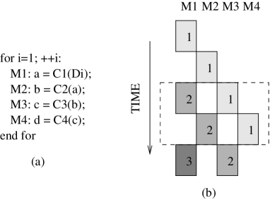
The software pipelining scheduling method makes use of parallel processing among DSP modules at the operation-scheduling level, not at the instruction level. Let us look at the loop body of Figure 6(a). Each set M444Note that M represents a set of operations of each module, not an operation itself. of an iteration depends on the previous set of operations as well as the previous iteration. As shown by the execution schedule of Figure 6(b), the set of operations of the 2nd iteration of M1 depends on, and must follow the set of operations of the 1st iteration of M2. From this basic software pipelining scheduling method, speed-up of the execution rate can be expected.
4.2.2 Data Dependencies
DSP modules of a DSP application based on the DRM are dependent on data associated with its topology. A dependence [Allan et al. (1995)] exists between two operations if interchanging their order affects the results. Dependencies constrain what can be done in parallel. Let and be operations such that precedes . must follow if reads data written by . is said to be data dependent on . Data dependence between two operations is extended to data dependence between two operational modules. There is another reason that one operation must wait for another operation. A control dependence exists between and if the execution of statement determines whether or not statement is executed. Therefore, even though is able to execute because of the available data, it may not execute because it is not known whether it is needed.
The DRM considers data dependencies, not control dependencies. Figure 7 gives an example of this. It shows part of an audio application that switches between Amplitude Modulation (AM) and Frequency Modulation (FM) demodulators, consisting of the filter, AM demodulation, FM demodulation,multiplex and sink modules. The audio application has data dependencies represented as (1), (2), (3), (4), and (5) and all the statements pertaining to the execution of modules. The control program is required to change the execution topology with the establishment of either (1) and (3), or (2) and (4) after the Channel Filter operation. Thus, it is necessary to have control dependencies as well as data dependencies between the Channel Filter and the AM demodulator, or between the Channel Filter and the FM demodulator. It implies the need of the dynamic reconfiguration that enables the execution topology to be adapted to the changeable environment.

5 An example of Application: The Radio Interface Part of a GSM BTS
As an example of implementation using EPspectra, this section describes the general architecture of a GSM network and the radio interface part of a GSM base station. The following sections describe the verification procedure of the three safety properties of the implementation that should be satisfied. In addition to the verification, the performance comparison between automatically generated code programs and hand-written code programs is analyzed.
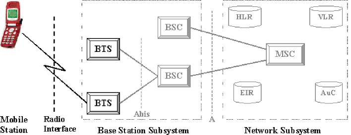
As shown in Figure 8, the GSM network can be generally divided into three main parts: the Mobile Station (MS), the Base Station Subsystem (BSS), and the Network SubSystem (NSS). The MS is the physical equipment used by a subscriber, most often a normal hand-held cellular telephone. The BSS connects the MS and the NSS. It is in charge of transmission and reception. The BSS consists of a Base Transceiver Station (BTS) and a Base Station Controller (BSC). The BTS comprises radio transmission and reception devices and also manages the signal processing related to the air interface. Each BTS has one to sixteen transceivers, depending on the density of users in the cell. The BSC controls a group of BTS and manages its radio resources, mainly through the allocation, release and hand-over of radio channels. The Mobile Switching Center (MSC) is the central component of the NSS. It performs the switching functions of the network and also provides connection to other networks. In addition, there are several kinds of registers, namely the Home Location Register (HLR), the Visitor Location Register (VLR), Equipment Identity Register (EIR), and the Authentication Center (AuC). The further description of the GSM system is given in [Mouly and Pautet (1993)].
We focus on the implementation of the GSM radio interface part between the MS and the BTS, particularly on the BTS side. It provides a multiple-access scheme and operations for the transformations between source information and radio waves. The implementation of the multiple access scheme has been excluded from our work. Instead, we present and implement the operations that have to be performed to pass from the speech source to radio waves and vice-versa.
5.1 Sequence of Operations between source information and radio waves
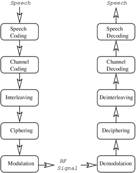
The sequence of operations for the radio interface of a GSM BTS is shown in Figure 9. Basically, after having transformed speech into compressed data blocks in speech coding, channel coding adds redundancy to the data blocks. The data blocks are interleaved and spread into pieces in interleaving, which are combined with flags to build up the bursts. Ciphering is applied to these bursts and then the resulting data is used to modulate the carriers in modulation. The reverse transformations are performed on the other side.
-
•
Speech coding algorithm, Regular Pulse Excitation with Long Term Prediction (RPE/LTP) [Lorenz (1998)] produces data blocks of 260 bits every 20ms.
-
•
Channel coding introduces redundancy into the data flow, increasing its rate by adding information calculated from the source data, in order to allow the detection or the correction of signal errors introduced during transmission. It forms a complete coded speech frame of 456 bits.
-
•
Interleaving consists in mixing up the bits of several code words, which in the modulated signal are spread over several code words. GSM coding blocks are interleaved on 8 bursts each of which consists of 57 bits.
-
•
Ciphering performs an exclusive or (XOR) operation between 2 bursts of each block and a secret recipe known only by the mobile station and BTS.
-
•
Modulation transforms the binary signal into a Gaussian Minimum Shift Keying (GMSK) [Murota and Hirade (1981)].
-
•
Once radio waves are captured by the antenna, the portion of the received signal which is of interest to the other side corresponding to radio waves to source information is determined by the multiple access rules. Demodulation takes place in this portion.
-
•
Deciphering performs the same operations by reversing the ciphering algorithm.
-
•
Deinterleaving merges two different 8-burst blocks into a 456-bit code word.
-
•
Channel decoding involves reconstructing the source information from the output of the demodulator, using the added redundancy to detect or correct possible errors in the output from the demodulator.
-
•
Speech decoding reconstructs the speech by passing the residual pulse first through the long-term prediction filter, and then through the short-term predictor.
6 Formal Verification
In this section, we explain what formal verification of Esterel programs means. As mentioned, Esterel is both a formal modeling language and a programming language. Esterel benefits from clear mathematical semantics that characterize a program as an FSM model. The Esterel FSM model is defined as a structure where is a set of input signals, a set of output signals, a set of states, the initial state, and a transition relation. is a set of 4-tuple , which represents a transition from to whenever the input event is true, generating the output event . The FSM model is the one that is used for simulation, execution and formal verification. A state of the FSM model is a stable configuration of the control points of the program. A transition from a system state is a reaction to some input event: the reaction leads to a new stable system. The FSM model has the advantage of exhaustively exhibiting the program behaviors. Formal verification is the activity of proving properties of programs and systems in a mathematical sense. In other words, verification consists in verifying the satisfaction of a set of properties over a FSM model of the program or system behavior.
Generally speaking, there are two types of properties that can be expressed: safety properties [Alpern et al. (1986)] and liveness properties [Alpern and Schneider (1985)]. Safety properties express the fact that “something bad will never happen.” Liveness properties express the fact that “something good will eventually happen.” For example, a typical safety property is ”The elevator will never move while the door is open” and a typical liveness property is ”If someone calls the elevator, then the elevator will eventually come”. In our experience, most of the properties are safety ones. When liveness is concerned, it is often reducible to bounded liveness, which is fundamentally a particular form of safety properties. Bounded liveness properties express the fact that “something good will eventually happen in at most k times units,” where k is a constant. For example, we can transform the liveness property of the elevator into a bounded liveness as follows: ”If someone calls the elevator, then the elevator will eventually come in less than 5 minutes”. Let us look into a way to directly apply these properties to the Esterel system.
6.1 Observer Properties
In the Esterel system, the users directly express the properties using the Esterel language. Let us consider a simple property that requires the following condition: “At each state, if signal A and B are present, then signal C in the next state should be present unless signal R is present. Otherwise it falls into an error state”. In Esterel, this property is written as follows:
module OBSERVER:
input A, B, C, R;
output BUG;
loop
   present [A and B] then
      pause;
      abort
         present C else emit BUG end
      when R
   else
      pause
   end present
end loop
end module
The pause statement waits for one time unit. The abort ... when cond construct kills its body as soon as the condition cond is true. This formal verification consists in checking if the signal properties such as BUG above can be emitted in some reachable states and for some input events. If the property is violated, the Xeve model-checker generates an input sequence of events that would have produced the error state.
6.2 Xeve
Xeve takes as inputs the FSM model expressed as a set of boolean equations in Blif format generated by the Esterel compiler. It makes use of the symbolic state space construction algorithm by means of Binary Decision Diagrams (BDDs) [Bryant (1986)], the internal representation of an FSM model for the reachable state space. Xeve provides two verification functions: minimising the number of states of the FSM model and checking the emission status of output signals. The first function is performed with respect to an equivalence notion called symbolic bisimulation [de Simone and Ressouche (1994)]. The second function checks two states for output signals: possibly emitted, which means there exists a reachable configuration that some inputs lead to the emitted output signals, and never emitted, which means there exists no reachable configuration that some inputs lead to the emitted output signals. More details on Xeve’s verification technique can be found in [Bouali (1998)].
6.3 Properties of the GSM Programs
Basically, all processing modules do their behaviors in parallel. Let us take a look at the following example.
module GSMsource2wave
   ...
   run source/SOURCE
    ||
   run speechcoding/P_MOD
    ||
   run channelcoding/P_MOD
    ||
   run interleaving/P_MOD
    ||
   run ciphering/P_MOD
    ||
   run modulation/P_MOD
    ||
   run sink/SINK
   ...
end module
Unless carefully programmed, the process of a module may prevent the process of the other modules from running due to missing signals. Let us look at Figure 10. The performance of parallelism can be enhanced as the process of an inside module is partitioned into two parts (i.e. the estimating and the computing function parts) running in parallel. It requires the cautious synchronization between the process of a module and that of another.

In Figure 10, the ‘Ack_from_Down’ signal of the speech coding module is synchronized with the ‘Ack_to_Up’ signal emitted by the channel coding module. As soon as ‘Ack_from_Down’ is received, the estimating function is performed on the speech coding module (i.e. run Estimate_Data). The ‘S_Compute_from_Up’ signal on the channel coding module is synchronized with the ‘E_Compute_to_Down’ signal emitted in the speech coding module. This synchronization activates the computing function on the channel coding module (i.e. run Compute_Data). However, Estimate_Data and Compute_Data submodules contain loop statements including ticks555Tick introduced in Esterel is thought of as logical time which represents the activation clock of a reactive program., the number of which being consumed is determined at the run time execution. It may cause deadlock to happen by the channel coding module to miss the signal coming from the speech coding module (which corresponds to the asterisked arrow () in Figure 10). There are occasions when the number of ticks being consumed are not transparent to programmers. We, therefore, add an explicitly synchronizing mechanism called Rendez-Vous. As shown in Figure 10, the ‘take’ signal on the channel coding module validates Rendez-Vous submodule on the speech coding module, which results in suspending the successive process of the speech coding module. This delays in emitting the ‘E_Compute_to_Down’ signal on the speech coding module. Afterwards, on receiving the ‘cancel’ signal coming from the channel coding module, Rendez-Vous kills this suspension.
The GSM programs process sample data; the data processed on the sources ends up being consumed on the sinks. All modules contain loop statements, which means that the programs may stall or may be in a situation in which some critical stage of a task is unable to finish. This fact must be verified for the safety of the programs. Accordingly, the requirements that should be satisfied by the above model are the following:
-
R1
The signal emitted by a module is always caught by the opposite modules (referred to as Rendez-Vous).
-
R2
The computed sample data on the source(s) will eventually be consumed on the sinks.
-
R3
Whenever the modules receive input signals, they emit the corresponding output signals within a bounded time-period.
Each safety property is then translated into an Esterel observer. The safety properties and the corresponding translations are as follows:
-
S1
Deadlock freedom: an important safety property is deadlock freedom. In the GSM program, deadlock occurs when one misses signals that should be received. The Rendez-Vous mechanism aims to avoid this synchronization deadlock by establishing an explicit synchronization between at least two signals of modules running in parallel. To guarantee that the program will never deadlock, it is sufficient to verify the Rendez-Vous mechanism, namely, by checking the satisfaction of the following safety property: any state at which the module emits ‘E_Compute_to_Down’ is preceded by a state at which the opposite ones are ready to receive ‘S_Compute_from_Up’. This is stated by the following Esterel observer:
module S1: input ReadytoReceive, E_Compute_to_Down; output S1_VIOLATED; loop await E_Compute_to_Down; abort emit S1_VIOLATED when pre(ReadytoReceive); end loop end module -
S2
Correctness: a major scheduling task of the GSM programs is to correctly deliver certain sample data computed on a source up to a sink by applying a sequence of operations to the corresponding data. The procedure begins from the source receiving ‘Ack_from_Down’ and ends when the sink emits ‘Ack_to_Up’. However, we note that all sample data computed on the source is not always consumed by the sink in the end. In fact, a certain amount of sample data can be skipped, depending on the specific conditions, e.g., a missed deadline happens since it is scheduled based on soft real-time constraints, there are changes to a type of modulation algorithm or an event, such as reset, occurs from the outside environment.
Each module consumes one or two ticks for an iteration of the loop statement from the input sample data to the corresponding output sample data. The GSM programs are divided into the operations of the transmission from source to radio wave and back. Each of them consists of five modules plus a source and a sink (See Figure 9). Suppose that each module consumes two ticks for a sample data, the sink finishes computing the sample data in no more than fourteen ticks (= D). The correctness property is as follows: for a state receiving ‘Ack_from_Down’ on the source, a state emitting ‘Ack_to_Up’ on the sink follows no more than D position. This is stated by the following Esterel observer:
module S2: constant D; input Ack_to_Up, Ack_from_Down; output S2_VIOLATED; await Ack_from_Down; abort await D tick; emit S2_VIOLATED when Ack_to_Up; end module -
S3
Safety-liveness: every module behaves like a sub-reactive program which waits for inputs and computes corresponding outputs in a cyclic manner. Each module contains a loop statement with a certain condition to exit. There is possibly a situation where some critical stage of a task is unable to finish, referred to as livelock. If one module is livelocked, the other modules would be blocked. The number of ticks being consumed for a period of receiving and responding to inputs is proportional to the length of a path between the module and the sink.
Figure 11 shows a signal-passing scenario of the GSM program performing operations from source information to radio waves. All the modules except the source and the sink wait for two input signals from the previous and next modules: await AckfromUp&Dwn. In an initial state, the signal coming from the next module is given as on. We consider quantifying the total number of ticks being consumed to compute given sample data on the source up to the sink. Each module contains two ‘pause’ identified by ‘await tick’ and seven modules compose a sequence of operations. Therefore, fourteen ticks are consumed in total, which is maximum number because the courses of operations for one sample data and another are interleaved.

Figure 11: A signal-passing scenario of the GSM program corresponding to from source to radio waves Considering that each module consumes two ticks in an iteration of a loop statement, the source receives an ack-signal in no more than fourteen ticks (=D) and yet D is also proportional to the length of the signal passing chain. The general form of the property is as follows: if holds at position , then holds at position , for . This is stated by the following Esterel observer:
module S3:
constant D;
input Is, Os;
output S3_VIOLATED;
loop
   await Is;
   abort
      await D tick;
      emit S3_VIOLATED
   when Os;
end loop
end module
This property can be applied separately to the source, the sink and the others. For example, (AckfromDwn, ComptoDwn) for the source, (AckfromUp, AcktoUp) for the sink, and (AckfromUp&Dwn, AcktoUp) for intermediate modules are event predicate pair being observed.
At the phase of combining the GSM programs with observers in the properties verifying procedure, the following program is defined consisting of the GSM program to be verified and three observers, S1, S2 and S3 to verify. In Xeve, the occurrence of S1_VIOLATED, S2_VIOLATED, and S3_VIOLATED is checked. We note that the GSM program is compiled directly into an executable code without modification. We will analyze the performance of the GSM program in Section 7.
module VERIFY_PROGRAM:
constant D:=14 : integer;
input <the program inputs>;
output <the program outputs>,
       S1_VIOLATED,
       S2_VIOLATED,
       S3_VIOLATED;

   run GSM
    ||
   run S1
    ||
   run S2
    ||
   run S3
end module
6.4 Verification Process
We verified the satisfaction of the properties in the GSM programs by confirming never emitted the property-signals including violated_deadlockfreedom, violated_correctness, and violated_liveness using Xeve. Figure 12 shows the result of verifying the status of the property-signals of the GSM program containing the operations of the transmission from source to radio waves in Xeve.
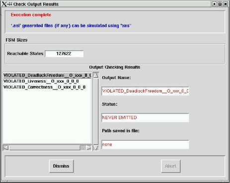
Generated reachable state space of two GSM Esterel programs (one describing the operations from source to radio waves and the other describing those of backward) amounts to 127622 and 116972 states, respectively.
The number of nodes of the BDD graphs representing these reachable state spaces are 66965 and 63390 respectively. It takes each program about 273 and 236 seconds-CPU time on Linux machine with 600Mhz Pentium processor and 516 RAM to generate the reachable state space. Note that these amounts were generated by the combination of the properties and the implementation of the Esterel programs.
7 Performance Results
Our performance analysis in the verification process was carried out on a Pentium 600MHz machine with 512MB of core memory and 516MB of swap space on Linux kernel 2.2.15. Esterel programs are compiled with the version 6.03 of the Esterel compiler into Blif formats666Berkeley Logical Interchange Format is an ASCII format developed at the university of Berkeley to describe a logic-level hierarchical circuit in textual form. and then optimized by Remlatch [Sentovich et al. (1996)] and Sis [Sentovich et al. (1992)]. The Remlatch processor is used to optimize the state encoding of the circuit and Sis is used to reduce the combinational logic introduced by the sequential optimisation of Remlatch. The optimized Blif code is translated into standard C code by the Esterel compiler. The executable code777The executable code is obtained by gcc version egcs-2.91.66 with the -O2 optimisation flag. is built up by integrating the C++ code of the data part and the above C code.
7.1 Performance Comparison
We provide the performance comparison of GSM applications built on EPspectra and Pspectra. Figure 14 and Figure 13 show the CPU requirement for the GSM programs to operate seven logical channels, respectively. Each logical channel includes the operations of the transmission from source information to radio waves and back.
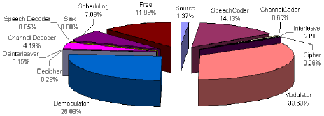
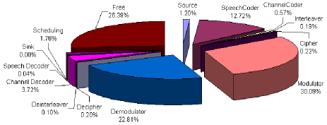
With respect to the scheduling segment, the GSM program implemented in EPspectra consumes CPU four times more than in Pspectra. It is because of the interface part which provides no scheduling functionality but connection between Esterel code and C++ code. Partially, the scheduling performance also varies to a large extent of the optimization of automatically generated code from Esterel. However, this overhead has no effect on the channel handling capability of signal processing process. For example, in Figure 13 11.98 percent of CPU are still available as free. Therefore, the performance in terms of the number of handled channels is the same.
7.2 Comparison of LoC (Lines of Code)
| code \ model | EPspectra | Pspectra |
|---|---|---|
| Esterel code | 1434 | not used |
| Esterel-generated C code | 10876 | not used |
| C/C++ code for interface part | 3181 | not used |
| C++ code for control part | not used | 8045 |
| Assembly code | 64310 | 13024 |
Table 1 makes the comparison of the loc of the control part of EPspectra and Pspectra for the GSM programs888The code corresponding to the data part of EPspectra is the same as is used in Pspectra.. The control part of EPspectra contains 1434 lines of the Esterel code and the Esterel code is translated into the C code corresponding to 10876 lines. The code used for the interface contains the C code for the access to the control part and the C++ code for the access to the data part.
With comparison of the assembly code composed of only the executable
code, the loc corresponding to EPspectra is 4.9 times larger
than the loc corresponding to Pspectra. Nevertheless, given
that the advantage of a general purpose system is to use the large
amount of memory, the loc is not an important issue for these
applications, as opposed to embedded applications. Instead, the cost
of extra loc can be absorbed by the benefit of the Esterel
methodology: simulation and verification.
Difficulties: Programmers with EPspectra need to be
familiar with programming in Esterel. In addition, in terms of
a degrading performance, this may be a fundamental constraint that
results from automatically generated codes.
It needs efficient techniques such as innovative scheduling techniques.
Advantages: EPspectra, whose features include the simulation and verification phases, facilitates the design and implementation of DSP applications. Moreover, it allows one to directly verify the actual code of Esterel programs that are compiled into an executable code. It guarantees that the Esterel programs satisfy the safety properties so long as all source code is proved correct and compiled to the targeted code.
8 Related Work
[Halbwachs et al. (1992), Halbwachs et al. (1993)] presented an example of specifying and verifying a real-time program using a synchronous data-flow language, Lustre. They introduced a subway control system which operates in a U-turn section. First, the subway control system, in which two verifiable problems, collision and derailment may happen, is specified in Lustre. Next, the critical properties are expressed as the invariance of some boolean Lustre expression. Temporal properties are handled with the allowance of references to the past with respect to the current instant. Once the environment representing behaviors of the subway control system and its properties to be verified are done in Lustre, they are verified whether the assertions are true or false using Lesar, its associated verification tool. The verification process runs relying on ’standard’ model checking [Clarke et al. (1986)] which leads to explicitly enumerating the reachable states and symbolic model checking [Burch et al. (1990)] which starts from a boolean formula and iteratively computes a sequence of formulas. The advantage of the work is that there is no manual transformation between the program that is verified and the code that is executed.
[Halbwachs et al. (1997)] presented linear relation analysis applied to the verification of quantitative time properties of both synchronous programs and linear hybrid systems.
[Jeannet et al. (1999)] proposed to dynamically select a suitable partitioning according to the property to be proved, avoiding exponential explosion of the analysis caused by in-depth detailed partitioning.
[Raymond et al. (1998), Halbwachs and Raymond (1999)] proposed to use synchronous observers to express both the relevance and the correctness of the test sequences. The relevance observer is used to randomly choose inputs satisfying temporal assumptions about the environment.
[Benveniste et al. (1992), Borgne et al. (1996)] presented an example of verification of real-time applications, using a synchronous language, Signal. The overall procedure from programming to verification is similar to that using Lustre. Signal approach provides the ease of implementing distributed systems including the features of proof and compilation.
9 Discussion
We have presented EPspectra for DSP applications development
and verification. EPspectra methodology achieves a substantial
principle of what we prove is what we execute [Berry (1989)]
straightforwardly; there is no gap between the program which is
verified and the code which is executed. All specification,
simulation, verification and execution are performed in it. We have
also demonstrated the implementation and verification of the radio
interface part of a GSM BTS using EPspectra. The performance
results are promising in that the benefit from the verification
functionality absorbs the impact on the overhead of automated
generated code.
In future work, we shall experiment with the automatic test-generation feature. The Esterel model-checker Xeve provides an automatic test-cases generation feature that can further reduce the time cost of the testing phase [Arditi et al. (1999)]: the generated test-cases are such that the Esterel FSM model’s states are totally covered, that is, every state of the model is visited and stimulated at least once by the test cases. With these test cases, the developers can detect more potential tricky bugs called corner cases, which are particularly hard to write a test case for.
We shall also attempt to verify timing constraints considering that the applications developed by EPspectra correspond to time-sensitive systems based on either hard real-time constraints or soft real-time constraints. The method introduced in [Closse et al. (2001)] can be used to verify quantitative timing constraints by using a time-driven automata.
Acknowledgements
We gratefully acknowledge discussions about Pspectra with John C. Ankcorn at MIT and about Esterel Verification Techniques with Robert de Simone at INRIA and about Timing Constraints Verification Techniques with Daniel Weil and Jacques Pulou at France Telecom R&D and about Software Development Methodology with Thierry Saunier at Thales. This research was supported by the DESS project associated with Information Technology for European Advancement (ITEA).
References
- Allan et al. (1995) Allan, V. H., Jones, R. B., Lee, R. M., and Allan, S. J. 1995. Software pipeling. ACM SIGPLAN Not. 27, 3 (sep), 367–432.
- Alpern et al. (1986) Alpern, B., Demers, A. J., and Schneider, F. B. 1986. Safety without stuttering. Inf. Process. Lett. 23, 4 (nov), 177–180.
- Alpern and Schneider (1985) Alpern, B. and Schneider, F. B. 1985. Defining liveness. Inf. Process. Lett. 21, 4 (oct), 181–185.
- Arditi et al. (1999) Arditi, L., Bouali, A., et al. 1999. Using esterel and formal methods to increase the confidence in the functional validation of a commercial dsp. In 4th Int. Workshop on Formal Methods for Industrial Critical Systems. Vol. 12. Springer Verlag.
- Benveniste et al. (1992) Benveniste, A., Borgne, M. L., and Guernic, P. L. 1992. Signal as a model for real-time and hybrid systems. In 4th European Symposium on Programming. Springer Verlag, 20–38.
- Benveniste et al. (1991) Benveniste, A., Guernic, P. L., and Jacquemot, C. 1991. Synchronous programming with events and relations: the signal language and its semantics. Elsevier Sci. Comput. Prog. 16, 2 (sep), 103–149.
- Berry (1989) Berry, G. 1989. Real time programming: Special purpose or general purpose languages. In IFIP Congress. North-Holland, 11–17.
- Berry (1996) Berry, G. 1996. Constructive semantics of esterel: From theory to practice (abstract). In 5th Int. Conf. on Algebraic Methodology and Software Technology. Vol. 1101. Springer Verlag, 225.
- Berry and team (1999) Berry, G. and team, E. 1999. The Esterel v5.92 System Manual. http://www.esterel.org.
- Borgne et al. (1996) Borgne, M. L., Marchand, H., Éric Rutten, and Samaan, M. 1996. Formal verification of signal programs: Application to a power transformer station controller. In 5th Int. Conf. on Algebraic Methodology and Software Technology. Vol. 1101. Springer Verlag, 271–285.
- Bose (1999) Bose, V. G. 1999. Design and implementation of software radios using a general purpose processor. Ph.D. thesis, MIT.
- Bouali (1998) Bouali, A. 1998. Xeve: an esterel verification environment. In 10th Int. Conf. on Computer Aided Verification. Vol. 1427. Springer Verlag.
- Bryant (1986) Bryant, R. E. 1986. Graph-based algorithms for boolean function manipulation. IEEE Trans. Comput. C-35, 8 (aug), 677–691.
- Burch et al. (1990) Burch, J. R., Clarke, E. M., McMillan, K. K., Dill, D. L., and Hwang, J. 1990. Symbolic model checking: states and beyond. In 4th Symposium on Logic in Computer Science. IEEE, 428–439.
- Clarke et al. (1986) Clarke, E. M., Emerson, E. A., and McMillan, K. L. 1986. Automatic verification of finite-state concurrent systems using temporal logic specifications. ACM Trans. Prog. Lang. Sys. 8, 2 (apr), 244–263.
- Closse et al. (2001) Closse, E., Poize, M., Pulou, J., Sifakis, J., Venter, P., Weil, D., and Yovine, S. 2001. Taxys: a tool for developing and verifying real-time properties of embedded systems. In 13th Int. Conf. on Computer Aided Verification. Vol. 2102. Springer Verlag.
- de Simone and Ressouche (1994) de Simone, R. and Ressouche, A. 1994. Compositional semantics of esterel and verification by compositional reductions. In 5th Int. Conf. on Computer Aided Verification. Springer Verlag, 441–454.
- Halbwachs et al. (1992) Halbwachs, N., Lagnier, F., and Ratel, C. 1992. Programming and verifying real-time systems by means of the synchronous data-flow programming language lustre. ieeese 18, 9 (sep), 785–793.
- Halbwachs et al. (1993) Halbwachs, N., Lagnier, F., and Raymond, P. 1993. Synchronous observers and the verification of reactive systems. In 3rd Int. Conf. on Algebraic Methodology and Software Technology. Springer Verlag, 83–96.
- Halbwachs et al. (1997) Halbwachs, N., Proy, Y., and Roumanoff, P. 1997. Verification of real-time systems using linear relation analysis. Kluwer For. Meth. Sys. Des. 11, 2 (aug), 157–185.
- Halbwachs and Raymond (1999) Halbwachs, N. and Raymond, P. 1999. Validation of synchronous reactive systems: from formal verification to automatic testing. In 5th Asian Computing Science Conf. Springer Verlag.
- Harel (1987) Harel, D. 1987. Statecharts: a visual formalism for complex systems. Elsevier Sci. Comput. Prog. 8, 3 (jun), 231–274.
- Jeannet et al. (1999) Jeannet, B., Halbwachs, N., and Raymond, P. 1999. Dynamic partitioning in analyses of numerical properties. In 6th Static Analysis Symposium. Springer Verlag.
- Jensen (1997) Jensen, E. D. 1997. Eliminating the hard/soft real-time dichotomy. Comput. and Cont. Eng. 8, 1 (feb), 15–19.
- Johnsson (2004) Johnsson, T. 2004. Efficient compilation of lazy evaluation. ACM SIGPLAN Not. 39, 4 (apr), 125–138.
- Lorenz (1998) Lorenz, D. 1998. Digital cellular telecommunications system (phase 2) (gsm); full rate speech; part 2: Transcoding (gsm 06.10 version 4.1.1).
- Mouly and Pautet (1993) Mouly, M. and Pautet, M. B. 1993. The GSM System for Mobile Communications. ISBN 2-9507190-07. Europe Media Duplication S.A.
- Murota and Hirade (1981) Murota, K. and Hirade, K. 1981. Gmsk modulation for digital radio telephony. IEEE Trans. Commun. com-29, 7 (jul), 1044–1050.
- Raymond et al. (1998) Raymond, P., Weber, D., Nicollin, X., and Halbwachs, N. 1998. Automatic testing of reactive systems. In 19th Real-Time Systems Symposium. IEEE, 200–209.
- Sentovich et al. (1992) Sentovich, E. M., Singh, K. J., Lavagno, L., Moon, C., Murgai, R., Saldanha, A., Savoj, H., Stephan, P. R., Brayton, R. K., et al. 1992. Sequential circuit design using synthesis and optimization. In 2th Int. Conf. on Computer Aided Design. IEEE, 328–333.
- Sentovich et al. (1996) Sentovich, E. M., Toma, H., and Berry, G. 1996. Latch optimization in circuits generated from high-level descriptions. In 6th Int. Conf. on Computer Aided Design. IEEE, 428–435.
- Vasconcellos (2000) Vasconcellos, B. W. 2000. Parallel signal-processing for everyone. M.S. thesis, MIT.
Appendix A. Glossary
-
MS
The GSM mobile station (or mobile phone) communicates with other parts of the system through the base-station system.
-
GSM
Global System for Mobile communications is the European standard for digital cellular telephone service.
-
BTS
The Base Transceiver Station handles the radio interface to the mobile station. The base transceiver station is the radio equipment (transceivers and antennas).
-
BSS
GSM Base Station Subsystem provides the interface between the GSM mobile phone and other parts of the GSM network. It consists of one or more base transceiver station (BTS) and one or more base station controller (BSC).
-
NSS
Network SubSystem performs the switching of calls between the mobile users, and between mobile and fixed network users.
-
MSC
Mobile Switching Center performs the telephony switching functions of the system. It also performs such functions as toll ticketing, network interfacing, common channel signalling, and others.
-
BSC
Base Station Controller provides the control functions and physical links between the MSC and BTS. It provides functions such as handover, cell configuration data and control of RF power levels in base transceiver stations.
-
HLR
Home Location Register database is used for storage and management of subscriptions. The home location register stores permanent data about subscribers, including a subscriber’s service profile, location information, and activity status.
-
VLR
Visitor Location Register database contains temporary information about subscribers that is needed by the MSC in order to service visiting subscribers.
-
EIR
Equipment Identity Register database contains information on the identity of mobile equipment to prevent calls from stolen, unauthorized or defective mobile stations.
-
AuC
Authentication Center provides authentication and encryption parameters that verify the user’s identity and ensure the confidentiality of each call.
-
DSP
Digital Signal Processing are specialized computer chips designed to perform speedy and complex operations on digitized waveforms. It is used in processing sound, such as voice phone calls, and video.
-
RPE/LTP
Regular Pulse Excitation with Long Term Prediction is used by GSM for full rate speech coding.
-
GMSK
Gaussian Minimum Shift Keying is the modulation technique used in GSM networks. It employs a form of FSK (Frequency Shift Keying).
-
GuPPI
General Purpose PCI I/O is the PCI appliance base for the SpectrumWare project. Its function is to provide an efficient means for moving a continuous stream of sampled data between a workstation’s main memory and an application-specific analog daughtercard.
See URL: http://www.sds.lcs.mit.edu/SpectrumWare/guppi.html. -
QAM
Quadrature Amplitude Modulation is a method for encoding digital data in an analog signal in which each combination of phase and amplitude represents one of sixteen four bit patterns. This is required for fax transmission at 9600 bits per second. This constellation, and therefore the number of bits which can be transmitted at once, can be increased for higher bit rates and faster throughput, or decreased for more reliable transmission with fewer bit errors. The number of ”dots” in the constellation is given as a number before the QAM, and is always two to the power of an integer from one (2QAM) to twelve (4096QAM). 64QAM is often used in digital cable television and cable modem applications.
Appendix B. Source Code
The complete source code of EPspectra is available in a public domain for the purpose of research. See http://www.inria.fr/planete/hkim/epspectra/. The GSM radio interface implementation consists of the downlink and uplink part. We present main Esterel and C code of the downlink part, respectively, in Appendix B.1 and B.2. The Esterel code in Appendix B.1 is the one that is verified and compiled/executed. Once it is translated into the corresponding C code with Esterel compiler, main function in Appendix B.2 calls the DNLINK function originated from the Esterel code. Each time DNLINK() is called in main function, a logical unit that is identified by the statement from a ’tick’ to the next is executed in Esterel code.
B.1 Downlink Esterel code
%##########################################################
%#  This module is downlink application with data flow model.
%##########################################################

module DNLINK:

type StrlSampleRange;
type UnsignedLL;
type UnsignedLong;

constant INITIAL_RANGE:StrlSampleRange;
constant INITIAL_UNSIGNEDLL:UnsignedLL;

%%%%%%%%%%%%%%%%%%%%%%%%%%%%
% parameter of modules
%%%%%%%%%%%%%%%%%%%%%%%%%%%%

constant RATE1 = 32000 : integer; %{160*50}%
constant RATE2 = 6600 : integer; %{33*50}%
constant RATE3 = 91200: integer; %{456*50}%
constant RATE4 = 118400: integer; %{592*50}%
constant RATE5 = 177600: integer; %{148*6*50}%

input on_TimeConstraint:integer;
input IP_Addr:string;
input User_Quit;
input InitRange:StrlSampleRange; %{0 1600}%
inputoutput FileSource_module:string;
inputoutput SpeechCoder_module:string;
inputoutput ChannelCoder_module:string;
inputoutput Interleaver_module:string;
inputoutput Cipher_module:string;
inputoutput Modulator_module:string;
inputoutput UDPSink_module:string;
function GET_FILESOURCE(string,integer):string;
function GET_SPEECHCODER():string;
function GET_CHANNELCODER():string;
function GET_INTERLEAVER():string;
function GET_CIPHER():string;
function GET_MODULATOR():string;
function GET_UDPSINK(string,integer):string;

procedure CONNECT_MODULES()(string,string,integer,integer);
procedure INITIAL_SINK()(string);
%
% body part
%
signal Mark_src2spcoder:=INITIAL_RANGE:StrlSampleRange,
       Mark_spcoder2chcoder:=INITIAL_RANGE:StrlSampleRange,
       Mark_chcoder2inleaver:=INITIAL_RANGE:StrlSampleRange,
       Mark_inleaver2cipher:=INITIAL_RANGE:StrlSampleRange,
       Mark_cipher2mod:=INITIAL_RANGE:StrlSampleRange,
       Mark_mod2snk:=INITIAL_RANGE:StrlSampleRange,
       Compute_src2spcoder, Compute_spcoder2chcoder,
       Compute_chcoder2inleaver, Compute_inleaver2cipher,
       Compute_cipher2mod, Compute_mod2snk,
       Ack_snk2mod:=INITIAL_RANGE:StrlSampleRange,
       Ack_mod2cipher:=INITIAL_RANGE:StrlSampleRange,
       Ack_cipher2inleaver:=INITIAL_RANGE:StrlSampleRange,
       Ack_inleaver2chcoder:=INITIAL_RANGE:StrlSampleRange,
       Ack_chcoder2spcoder:=INITIAL_RANGE:StrlSampleRange,
       Ack_spcoder2src:=INITIAL_RANGE:StrlSampleRange,
       RDV_snk2mod, RDV_mod2cipher, RDV_cipher2inleaver,
       RDV_inleaver2chcoder, RDV_chcoder2spcoder,
       RDV_spcoder2src,Ready2Receive
in
%%%%%%%%%%%%%%%%%%%%%
% create modules
%%%%%%%%%%%%%%%%%%%%%
abort
   await IP_Addr;
   emit FileSource_module(GET_FILESOURCE("papin2.au",0));
   emit SpeechCoder_module(GET_SPEECHCODER());
   emit ChannelCoder_module(GET_CHANNELCODER());
   emit Interleaver_module(GET_INTERLEAVER());
   emit Cipher_module(GET_CIPHER());
   emit Modulator_module(GET_MODULATOR());
   emit UDPSink_module(GET_UDPSINK(?IP_Addr,5001));
%%%%%%%%%%%%%%%%%%%%%%%%%%
% make topology
%%%%%%%%%%%%%%%%%%%%%%%%%%
  call CONNECT_MODULES()(?UDPSink_module,?Modulator_module,RATE5,8);
  call CONNECT_MODULES()(?Modulator_module,?Cipher_module,RATE4,8);
  call CONNECT_MODULES()(?Cipher_module,?Interleaver_module,RATE4,8);
  call CONNECT_MODULES()(?Interleaver_module,?ChannelCoder_module,RATE3,8);
  call CONNECT_MODULES()(?ChannelCoder_module,?SpeechCoder_module,RATE2,8);
  call CONNECT_MODULES()(?SpeechCoder_module,?FileSource_module,RATE1,8);

  call INITIAL_SINK()(?UDPSink_module);
  await InitRange;
%%%%%%%%%%%%%%%%%%%%%%%%%%
% initialize parameters
%%%%%%%%%%%%%%%%%%%%%%%%%%
  [
     emit Ack_spcoder2src(?InitRange);
   ||
     run FileSource/
    SOURCE[signal FileSource_module/Name;
           signal Mark_src2spcoder/E_Mark_to_Down;%{mark1}%
           signal Compute_src2spcoder/E_Compute_to_Down;
           signal Ack_spcoder2src/Ack_From_Down;
           signal RDV_spcoder2src/snooping%{;
           signal FileSource_COMPUTEDSR/ComputedSRange}%];
   ||
      run SpeechCoder/
    P_MOD[signal SpeechCoder_module/Name;
          signal Mark_src2spcoder/S_Mark_from_Up;%{mark1}%
          signal Compute_src2spcoder/S_Compute_from_Up;%{}%
          signal Ack_spcoder2src/Ack_to_Up;%{}%
          signal RDV_spcoder2src/sig_on;%{}%
          signal Ready2Receive/Ready2Receive;
          signal Mark_spcoder2chcoder/E_Mark_to_Down;%{mark2}%
          signal Compute_spcoder2chcoder/E_Compute_to_Down;%{wire2}%
          signal Ack_chcoder2spcoder/Ack_From_Down;%{wire3}%
          signal RDV_chcoder2spcoder/snooping%{;
          signal SpeechCoder_COMPUTEDSR/ComputedSRange}%];
   ||
      run ChannelCoder/
    P_MOD[signal ChannelCoder_module/Name;
          signal Mark_spcoder2chcoder/S_Mark_from_Up;%{mark2}%
          signal Compute_spcoder2chcoder/S_Compute_from_Up;%{wire2}%
          signal Ack_chcoder2spcoder/Ack_to_Up;%{wire3}%
          signal RDV_chcoder2spcoder/sig_on;%{wire4}%
          signal Ready2Receive/Ready2Receive;
          signal Mark_chcoder2inleaver/E_Mark_to_Down;%{snk1}%
          signal Compute_chcoder2inleaver/E_Compute_to_Down;%{}%
          signal Ack_inleaver2chcoder/Ack_From_Down;%{from sink1}%
          signal RDV_inleaver2chcoder/snooping%{;
          signal ChannelCoder_COMPUTEDSR/ComputedSRange}%];
   ||
      run Interleaver/
    P_MOD[signal Interleaver_module/Name;
          signal Mark_chcoder2inleaver/S_Mark_from_Up;%{mark2}%
          signal Compute_chcoder2inleaver/S_Compute_from_Up;%{wire2}%
          signal Ack_inleaver2chcoder/Ack_to_Up;%{wire3}%
          signal RDV_inleaver2chcoder/sig_on;%{wire4}%
          signal Ready2Receive/Ready2Receive;
          signal Mark_inleaver2cipher/E_Mark_to_Down;%{snk1}%
          signal Compute_inleaver2cipher/E_Compute_to_Down;%{}%
          signal Ack_cipher2inleaver/Ack_From_Down;%{from sink1}%
          signal RDV_cipher2inleaver/snooping%{;
          signal Interleaver_COMPUTEDSR/ComputedSRange}%];
   ||
      run Cipher/
    P_MOD[signal Cipher_module/Name;
          signal Mark_inleaver2cipher/S_Mark_from_Up;%{mark2}%
          signal Compute_inleaver2cipher/S_Compute_from_Up;%{wire2}%
          signal Ack_cipher2inleaver/Ack_to_Up;%{wire3}%
          signal RDV_cipher2inleaver/sig_on;%{wire4}%
          signal Ready2Receive/Ready2Receive;
          signal Mark_cipher2mod/E_Mark_to_Down;%{snk1}%
          signal Compute_cipher2mod/E_Compute_to_Down;%{}%
          signal Ack_mod2cipher/Ack_From_Down;%{from sink1}%
          signal RDV_mod2cipher/snooping%{;
          signal Cipher_COMPUTEDSR/ComputedSRange}%];
   ||
      run Modulator/
    P_MOD[signal Modulator_module/Name;
          signal Mark_cipher2mod/S_Mark_from_Up;%{mark2}%
          signal Compute_cipher2mod/S_Compute_from_Up;%{wire2}%
          signal Ack_mod2cipher/Ack_to_Up;%{wire3}%
          signal RDV_mod2cipher/sig_on;%{wire4}%
          signal Ready2Receive/Ready2Receive;
          signal Mark_mod2snk/E_Mark_to_Down;%{snk1}%
          signal Compute_mod2snk/E_Compute_to_Down;%{}%
          signal Ack_snk2mod/Ack_From_Down;%{from sink1}%
          signal RDV_snk2mod/snooping%{;
          signal Modulator_COMPUTEDSR/ComputedSRange}%];
   ||
      run UDPSink/
    SINK[signal UDPSink_module/Name;
         signal Mark_mod2snk/S_Mark_from_Up;%{snk2}%
         signal Compute_mod2snk/S_Compute_from_Up;
         signal Ack_snk2mod/Ack_to_Up;
         signal RDV_snk2mod/sig_on;
         signal Ready2Receive/Ready2Receive%{;
         signal UDPSink_COMPUTEDSR/ComputedSRange}%];
   ]
when User_Quit
end signal
end module
B.2 Downlink main C code
#include <stdio.h>
#include <sys/time.h>
#include "GSM_DNLINK.h"

main(int argc,char** argv){
  char *addr=(char *)malloc(sizeof(char[16]));
  if (argc < 2)
    strcpy(addr,"localhost");
  else
    strcpy(addr,argv[1]);
  DNLINK();
  DNLINK_I_IP_Addr(addr);
  DNLINK();
  DNLINK_I_InitRange("0 1600");
    while(1)
    DNLINK();
}