Application of interactive parallel visualization for commodity-based clusters using visualization APIs
Abstract
We present an efficient and inexpensive to develop application for interactive high-performance parallel visualization. We extend popular APIs such as Open Inventor and VTK to support commodity-based cluster visualization. Our implementation follows a standard master/slave concept: the general idea is to have a “Master” node, which will intercept a sequential graphical user interface (GUI) and broadcast it to the “Slave” nodes. The interactions between the nodes are implemented using MPI. The parallel remote rendering uses Chromium. This paper is mainly the report of our implementation experiences. We present in detail the proposed model and key aspects of its implementation. Also, we present performance measurements, we benchmark and quantitatively demonstrate the dependence of the visualization speed on the data size and the network bandwidth, and we identify the singularities and draw conclusions on Chromium’s sort-first rendering architecture. The most original part of this work is the combined use of Open Inventor and Chromium.
keywords:
Interactive visualization, visualization APIs, commodity-based cluster visualization, parallel visualization, remote rendering, Chromium, Open Inventor, VTK, MPI.Computers & Graphics key words: Computer Graphics Applications: Scientific visualization - Physics, Engineering; Computer Graphics Methodologies: Fundamentals of Computer Graphics - Hardware Architecture (Parallel processing), Methodology and Techniques (Interaction techniques), Graphics Utilities (Graphics packages).
, , , , ,
1 Introduction
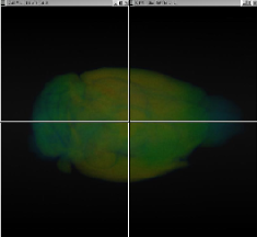
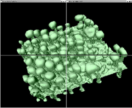
We are interested in large scale high-performance scientific parallel visualization with real-time interaction. More precisely, we want to support the interactive extraction of insight from large sets of data. Also, in order not to miss important details in the data, we would like to develop high resolution visualization. Our interest is motivated by today’s technological advances, which stimulate and facilitate the development of increasingly complicated mathematical models. Visualization with real-time interaction is essential for better analysis and understanding of the masses of data produced by such models, or by devices such as Magnetic Resonance Imaging (MRI) and laser-microscope scanners. Some of the applications that we are interested in and work on are given on Figure 1. Others come from high-energy physics, climate modeling, etc. Currently the size of the data sets that we are dealing with is around GB.

We develop an inexpensive and, as the results show, efficient application. The approach is as follows:
-
•
Do remote parallel rendering to a large tiled display (see for example Figure 1 where we show displays composed of tiles).
-
•
Use commodity-based clusters connected with high speed network.
-
•
Extend and combine already existing APIs such as Chromium, Open Inventor, VTK, etc.
The APIs considered are open source. Open Inventor (see [21, 22]) is a library of C++ objects and methods for building interactive 3D graphics applications, VTK (see [17, 18]) is another widely used API for visualization and image processing, and Chromium (see [7, 8, 4, 11]) is an OpenGL [16] interface for cluster visualization to a tiled display. Chromium is based on WireGL [9] and provides a scalable display technology. The latest Chromium paper [10] reports on the implementation of components (stream processing units, or SPUs) that can be used in sort-last parallel graphics applications. More on the sort-last parallel rendering approach can be found in [13] and [23].
There are feasible alternatives to our approach. For example, the tiled display can be replaced with a high resolution flat panel driven by a single workstation, the visualization clusters can be replaced with fast sequential machines, and the process of extending and combining already existing APIs can be replaced with building the entire visualization system from scratch. The IBM’s T221 display with its maximum resolution of brings to the scientist’s desktop a resolution that is high enough for many applications. For such cases this is a preferred alternative and we have it as an option in our implementation. Similarly, for “small” data sets we prefer sequential processing. Extending and combining visualization APIs is a popular and in many cases preferred development approach since one can easily leverage already existing and powerful APIs. Examples are the extension of VTK to ParaView (see [12]) and parallel VTK (see [1]), VisIt (see [3]), etc. Building an entire visualization system from scratch may be efficient for very specific requirements, but in general is expensive and time consuming (see for example NASA’s long term project ParVox [15]). Our goals, apart from developing the application outlined above, also include studying and identifying the singularities of the Chromium API. We concentrate on Chromium’s sort-first rendering, a model inherited, and further developed from the WireGL API.
The parallel model that we consider is MIMD (multiple instructions – multiple data). MIMD parallel models are common in the design of parallel visualization software for clusters of workstations. A fundamental framework is when cluster nodes process separate parts of a global scene and their output is composited and rendered to a tiled display. Providing MIMD model visualization systems with efficient user interaction has become a task of great interest. See for example [20]. The continuous interest also prompted the development of a new cluster rendering utility toolkit (CRUT) which was reported in [2]. CRUT is a glu-like toolkit that will facilitate the development of user interaction within Chromium, and hence the development of applications and visualization API extensions like the one that we developed. We pursue a Master/Slave paradigm: we declare one of the cluster nodes as GUI Master, use the Master to intercept the sequential user input, and broadcast that input in a user defined protocol to the other nodes (here called Slave nodes). This yields a system where the GUI Master sends to the Slave nodes instructions of “how and when” to redraw their part of the scene. The user interface in this case is part of the visualization software. Another implementation is to have the GUI Master separate from the visualization software. The interaction in this case would be through a GUI window that will simulate a “parallel interaction device” that takes a sequential user input and broadcasts it to the cluster nodes (through sockets). The details are given in the following sections.
The article is organized as follows. In Section 2 we describe our model framework and its implementation in extending Open Inventor and VTK. Next (in Section 3) we discuss issues that are important for the development of high performance visualization on clusters of workstations. Also, we provide some of our performance results. The last section (Section 4) summarizes the results of this work.
2 Parallel GUI model and implementation
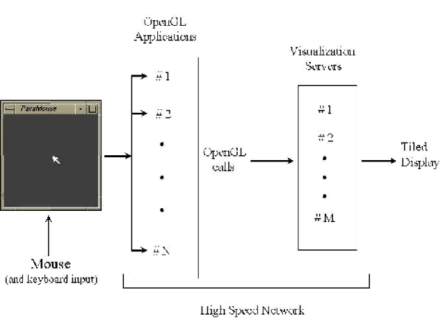
Parallel GUI for a MIMD parallel visualization model requires the presence of a Master node that will synchronize with the other nodes the redrawing of the consecutive scenes according to a sequential user input. We consider two variations of parallel GUI. Both have similar visualization pipelines (see Figure 2). The parallel GUI (ParaMouse) gets the sequential user input (through mouse, keyboard, etc.) and broadcasts it to the OpenGL applications through sockets. Every application is visualizing a separate part of a global scene. The applications are bound together by MPI communications. The OpenGL calls that the applications make are intercepted by Chromium and sent through the network to the visualization servers, which composite the input and render it to a tiled display.
Chromium’s parallelization model (denoted in the article by CPM) is represented with the pseudo-code:
  glXMakeCurrent(getDisplay(), getNormalWindow(),
                 getNormalContext());
  if (clearFlag)
    glClear(GL_COLOR_BUFFER_BIT | GL_DEPTH_BUFFER_BIT);
  glBarrierExecCR(MASTER_BARRIER);

  do sequential OpenGL rendering of the local scene

  glBarrierExecCR(MASTER_BARRIER);
  if (swapFlag)
    glXSwapBuffers(getDisplay(), getNormalWindow());
  else
    glXSwapBuffers(getDisplay(), CR_SUPPRESS_SWAP_BIT);
where the display obtained is composited if clearFlag is for all processors, swapFlag is for processor with rank , and for the rest, and tiled if clearFlag and swapFlag are only for processor with rank .
To extend Open Inventor and VTK (or any API) to support interactive cluster visualization within the above framework we did the following:
-
•
Apply the CPM to the APIs rendering method(s).
-
•
Implement the ParaMouse parallel GUI or extend the API’s GUI using the Master-Slave concept.
To implement the first step for Open Inventor we extended the SoXtRenderArea::redraw() method. For VTK this step is implemented by David Thompson, Sandia National Laboratory [19]. We implemented in Open Inventor the Master-Slave concept by extending the GUI that ivview provides. Function main in ivview was extended by implementing the pseudo-code:
  declare processor with rank 0 as Master;
  if (Master)
    run GUI as implemented in ivview;
  else
    listen for instructions from the Master;
We extended the callback functions triggered by the devices that Open Inventor’s GUI handles (mouse, keyboard, etc). The callback functions responding to user input have MPI_Isend of the invoked user input in the Master node to the Slave nodes. The Slave nodes are in “listening” mode (MPI_Recv or MPI_Irecv while animating), which is given with the pseudo-code below, and upon receiving data, representing instructions in an internally defined protocol, they call the action for the invoked input and redraw their part of the global scene (if necessary).
  // Initialize Inventor
  SoDB::init();
  SoNodeKit::init();
  SoInteraction::init();

  // Build the Inventor’s objects and scene graphs
  SoSeparator *root = new SoSeparator;
  root->ref();
  readScene(root, files);

  // Create a Slave node ExaminerViewer
  SoExaminerViewer *viewer = new SoExaminerViewer(crrank);
  viewer->setSceneGraph(root);

  // Chromium initialization
  crctx = crCreateContextCR(0x0, visual);
  crMakeCurrentCR(crwindow, crctx);
  glBarrierCreateCR( MASTER_BARRIER, crsize);

  glEnable(GL_DEPTH_TEST);
  viewer->mainLoop();
The SoExaminerViewer class is based on the Open Inventor’s SoXtExaminerViewer class. The difference is that SoExaminerViewer does not have Xt window interface function calls and the rendering is with the CPM.
The user interface is through the ivview window (see Figure 3, left), which is blank and used only for the user input. The scene is drawn in separate windows/tiles. The example from Figure 3 (right) shows a display with tiles. There are applications running, each of which visualize a sphere.
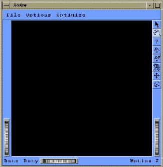
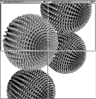
The scene is rendered in parallel on the tiled display. The interactive user interface is through the ivview window, with the functionality that ivview provides.
In VTK’s Master-Slave model we extend the vtkXRenderWindowInteractor class by:
-
•
Implementing “pure” X Windows GUI (no GL calls).
-
•
Adding MPI send/receive calls for mouse and keyboard events.
For the ParaMouse interface we added in VTK a new interactor style,
called vtkInteractorStylePMouse.
3 Observations and performance results
We did our implementation and testing on a Beowulf cluster with nodes, each node with Pentium III processors, running at 1 GHz. Every node has Quadro2 Pro graphics card. The nodes are connected into a local area network with communications running through Mbit/sec fast Ethernet or Gbit/sec fiber optic network. More about the general performance of this particular machine can be found in [14].
The experience that we had in developing interactive parallel visualization is summarized as follows:
-
1.
For the parallel model considered performance is problem and interaction specific.
For example, depending on the data and the user interaction, the entire global scene may be mapped to a single tile of the display. Also, the Chromium bucketing strategy [8, 4, 11] will not work for scenes composited of non-localized consecutive polygons. - 2.
-
3.
We can send approximately “small” (less then 100 bytes) messages/sec (see [14]).
-
4.
Chromium automatically minimizes data flow, except for geometry flow (see below).
-
5.
It is advisable to keep small static scenes in display lists (see below).
The network data flow is usually the bottleneck in the visualization pipeline that we consider. Chromium provides several techniques to minimize it. They are: simplified network protocol, bucketing, and state tracking (see [8, 4, 11]). None of these techniques however are intended for the automatic minimization of the geometry flow, which usually is the most expensive component. For example in animation the same objects are drawn without (or with minimal) change from frame to frame. Nevertheless the scene is transmitted over the network for every frame, creating an enormous bottleneck, as shown in the next example. Data flow minimization techniques that exploit spacial or temporal coherence of consecutive frames (see for example [24]) are not supported within the current framework.
The following example illustrates items and from the above observations. We use a small static scene composed of spheres with spikes, as the ones shown on Figure 3, right. Each sphere is composed of triangles. Sequentially, one sphere is drawn by the Open Inventor at a rate of frames/sec, i.e. triangles/sec. For spheres the rate is frames/sec or triangles/sec, etc. The speed of visualizing spheres on processors ( tiles) is approximately frames/sec. The composited visualization ( processors, tile) is approximately frames/sec. Runs with various problem sizes and parallel visualization configurations give similar results in favor of the sequential execution.
The enormous difference is due to the fact that in the first case the scene resides in the graphics card memory, while in the second the same scene is transmitted over the network for every frame. Table gives more results related to the network’s bandwidth bottleneck and the overall performance of the system. The results are for different applications using the Mbit and the Gbit network. The first one, mouse brain, comes from medical science and is a 3D surface of a mouse brain. The size of the data is MB. The Mbit network gets saturated and the frame rate of frames/second is expected, since the data traffic, although dependent on user interaction and locality of the scene polygons, is proportional to the data size. The frames/second translates to seconds per frame. The network transfer takes seconds. The next application, fluid flow, is an isosurface extracted from a fluid flow simulation data. The beetle head is also an isosurface. It was extracted from the X-ray computed microtomography data of an Alaskan spruce bark beetle. With performance mainly depending on the data size we observe that doubling the data size reduces the frame rate two times. Another application type that we tested is ray tracing volume visualization. We applied it to X-ray computed microtomography data of a rock sample of size GB. This is an example where a substantial part of the visualization is done in the CPU and only the result, in terms of OpenGL primitives, is sent through the network. On the Mbit network we get seconds per frame. seconds are spent in the ray tracing algorithm (run on cluster nodes with dual processor on each node) and seconds in transfer and rendering of the OpenGL commands issued in the ray tracing algorithm.
Switching to the Gbit network approximately doubles the performance results. Similar improvement was observed in [14] for various numerical analysis applications. The ray casting relies mostly on the CPU’s performance and switching to the Bbit network did not show any speed up.
| Frames per second using | |||
|---|---|---|---|
| Application | Size | Mbit network | Gbit network |
| mouse brain | 16 MB | ||
| fluid flow | 40 MB | ||
| beetle head | 80 MB | ||
Table . Dependence of the visualization speed on the data size and the network bandwidth for different applications. The global scene is split into and rendered by Chromium rendering SPUs to tiles display.
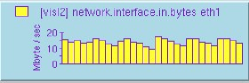
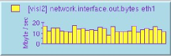
We used SGI’s pmchart to monitor the network traffic for the different applications described above and in Table . The network gets saturated for the applications discussed. The network traffic in and out of every cluster node looks like the one given on Figure 4.

The non-automatic mechanism that Chromium provides for acceleration (minimization) of the geometry flow is display lists. They are supported by sending the lists to each rendering server, and thus guaranteeing their presence on the server when they are called. Display lists in Open Inventor are created for the parts of the scene that have as root SoSeparator nodes with field renderCaching turned ON or AUTO (for more information see [21], pages -). Using display lists we get a speed of frames/sec for visualizing spheres by processors on composited display, and frames/sec on tiled display. Different parallel and display configurations illustrate the same order of improvement. These results are comparable to the sequential ones. The trade-offs are that the process is not automatic and that the display lists are broadcast to all rendering servers and thus replicating the scene in each node. Work on the automatic optimization of the geometry data flow can be found in [5].
4 Conclusions
We developed an application for interactive parallel visualization on tiled displays for commodity-based clusters. We used Chromium’s parallel rendering and extended popular visualization APIs, such as Open Inventor and VTK. The most original part of this work is the combined use of Open Inventor and Chromium. We gave implementation details and described our experience in the combined use of the Chromium’s rendering technology with Open Inventor and VTK. A general conclusion is that fast sequential visualization often relies on graphics acceleration hardware, data sampling methods, static scenes, and data size within the hardware limitations, while the visualization developed does not require expensive graphics hardware, provides high resolution, facilitates well the visualization of time-varying scenes, and can handle large data sets. We demonstrated a low cost (time, money, effort, etc.) of development. Our benchmarks quantitatively demonstrated the bottleneck that the network’s bandwidth presents in the sort-first rendering architecture. This bottleneck makes the sort-first architecture more appealing for time-varying data sets, commodity-based clusters with slow (or no) graphics acceleration, and visualization algorithms that rely on the CPU’s speed, such as ray casting.
Acknowledgments. We would like to thank Beverly Tomov from Cold Spring Harbor Laboratory, NY, for her attentive editing and remarks. We thank the anonymous referees whose constructive remarks improved the presentation. We also thank Keith Jones from the BNL’s Environmental Research and Technology Division for providing the data produced by the synchrotron-based computed microtomography at the Brookhaven National Synchrotron Light Source.
References
- [1] J.Ahrens, C.Law, K.Martin, M.Papka, W.Schroeder, A Parallel Approach for Efficiently Visualizing Extremely Large, Time-Varying Data Sets, Technical Report #LAUR-00-1620 (Los Alamos National Laboratory, NM, USA, 2000).
-
[2]
Dale Beermann,
CRUT: The Cluster Rendering Utility for Chromium,
Internet address (accessed on 05/2003):
http://www.cs.virginia.edu/drb3t/crut.ps -
[3]
E.Brugger,
Visit: A Component-Based, Parallel Visualization Package,
DOE, Computer Graphics Forum 2001,
Internet address (accessed on 08/2002):
http://www.emsl.pnl.gov:2080/docs/doecgf2001/abstractlist.html - [4] I.Buck, G.Humphreys, and P.Hanrahan, Tracking Graphics State for Networked Rendering, Proceedings of SIGGRAPH/Eurographics Workshop on Graphics Hardware (Interlaken, Switzerland, 2000) 87-95.
- [5] Nathaniel Duca, Peter Kirchner, James Klosowski, Stream Caching: Optimizing Data Flow within Commodity Visualization Clusters, Workshop on Commodity-Based Visualization Clusters, October 2002.
-
[6]
W. Gropp,
Tutorial on MPI: The Message-Passing Interface,
Internet address (accessed on 06/2002):
http://www-unix.mcs.anl.gov/mpi/tutorial/index.html. -
[7]
G. Humphreys,
Chromium Documentation, Version BETA,
Internet address (accessed on 06/2002):
http://chromium.sourceforge.net/ - [8] Greg Humphreys, Ian Buck, Matthew Eldridge, Pat Hanrahan, Distributed Rendering for Scalable Displays, Proceedings of Supercomputing 2000 (Dallas, TX, USA, 2000).
- [9] G. Humphreys, M. Eldridge, I. Buck, G. Stroll, M. Everett, P. Hanrahan, WireGL: A Scalable Graphics System for Clusters, Proceedings of SIGGRAPH 2001 (Los Angeles, CA, USA) 129-140.
- [10] Greg Humphreys, Mike Houston, Ren Ng, Randall Frank, Sean Ahern, Peter D. Kirchner, James T. Klosowski, Chromium: A Stream-Processing Framework for Interactive Rendering on Clusters, Proceedings of SIGGRAPH 2002 (San Antonio, TX, USA) 693-712.
- [11] Homan Igely, Gordon Stoll, and Pat Hanrahan, The Design of a Parallel Graphics Interface, Proceedings of SIGGRAPH 1998 (Orlando, FL, USA) 141-150.
-
[12]
ParaView: Parallel Visualization Application,
Internet address (accessed on 08/2002):
http://www.paraview.org/HTML/Index.html - [13] Marcelo Magallon, Matthias Hopf, Thomas Ertl, Parallel Volume Rendering Using PC Graphics Hardware, Proceedings of the 2001 Pacific Graphics Conference.
- [14] V. Mirinavicius, Investigation of MPI performance in Parallel Linear Algebra Software on Linux Beowulf Supercomputers, Technical Report (to appear), Brookhaven National Laboratory, Upton, NY, 2002.
-
[15]
NASA, Jet Propulsion Laboratory,
ParVox, A Parallel Splatting Volume Rendering System,
Internet address (accessed on 08/2002):
http://alphabits.jpl.nasa.gov/ParVox/ - [16] J. Neider, T. Davis, and M. Woo (OpenGL Architecture Review Board), OpenGL Programming Guide : The Official Guide to Learning OpenGL, Release , Addison-Wesley Publishing Company, Boston, May 1996.
- [17] W. Schroeder, K.Martin, L.Avila, C. Law The Visualization Toolkit User’s Guide, Kitware, Inc.
- [18] W. Schroeder, K.Martin, B.Lorensen, The Visualization Toolkit: An Object-Oriented Approach to D Graphics, Prentice-Hall PTR.
-
[19]
David Thompson and Gary Templet,
CPlant, VizClusters, VTK, Chromium,
DOE Computer Graphics Forum - April, 2002 (Montauk, NY),
Internet address (accessed on 08/2002):
http://www.ccd.bnl.gov/visualization/doecgf_2002/ - [20] IEEE Visualization 2002, workshop on: Commodity-Based Visualization Clusters, Proceedings of IEEE Visualization, 2002.
- [21] J. Wernecke, The Inventor Mentor : Programming Object-Oriented 3D Graphics with Open Inventor, Addison-Wesley Publishing Company, NY, November 1995.
- [22] Open Inventor C++ Reference Manual: The Official Reference Document for Open Inventor, Release 2, Addison-Wesley Publishing Company, January 1994.
- [23] Brian Wylie, Constantine Pavlakos, Vasily Lewis, and Ken Moreland, Scalable Rendering on PC Clusters, IEEE Computer Graphics and Applications, July/August 2001 (Vol.21, No.4), pp. 62-70.
- [24] Ilmi Yoon and Ulrich Neumann, Web-Based Remote Rendering with IBRAC, Euroghraphics 2000 (Volume 19, Number 3).