The use of Ethernet in the DataFlow of the ATLAS Trigger & DAQ
Abstract
The article analyzes a proposed network topology for the ATLAS DAQ DataFlow, and identifies the Ethernet features required for a proper operation of the network: MAC address table size, switch performance in terms of throughput and latency, the use of Flow Control, Virtual LANs and Quality of Service. We investigate these features on some Ethernet switches, and conclude on their usefulness for the ATLAS DataFlow network.
I Introduction
ATLAS is one of the five experiments foreseen to run on the LHC (Large Hadron Collider) which is currently being built at CERN. The proton-proton bunch crossings occur in ATLAS at approximately 40 MHz, the detector recording around 2 MBytes of data per event111The data acquired from one bunch crossing represents an event.. The amount of raw data generated by the detector is extremely large: 80 TBytes/second. However the final data rate which must be recorded to mass storage is of a few tens of MBytes/second.
The ATLAS TDAQ (Triggered Data Acquisition) system selects the interesting events using a three layer trigger architecture: LVL1 (level 1), LVL2 (level2), and the EF (Event Filter). The LVL1 trigger is entirely build in hardware, while LVL2 and the EF are implemented using PC farms. The output rate of LVL1 can reach 75 KHz, while the LVL2 output rate is around 2 KHz.
This paper presents results of investigations into the Ethernet features required for a proper operation of a network based TDAQ system, which reads data from the Level 1 trigger output, runs LVL2 algorithms and supplies the validated events to the Event Filter.
II ATLAS TDAQ Network-Based Architecture
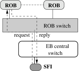
The ATLAS TDAQ Network-Based Architecture HP03 is presented in Figure 1. All the nodes except the ROBs (Read Out Buffers) are PCs. The ROBs interface to the network is FE UTP (Fast Ethernet, Unshielded Twisted Pair), while GE (Gigabit Ethernet) UTP is used for PCs. The network switches are interconnected through GE optical fibre links.
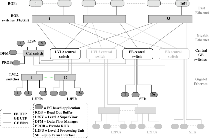
The events selected by the LVL1 trigger are buffered in approximately 1600 ROBs (Read Out Buffers) at a rate up to 75 KHz. The DataFlow system (everything below the ROBs in Figure 1) receives RoI (Region of Interest) information from the LVL1 trigger. The RoI points to the subset of event data which led to the level 1 accept decision. The DataFlow system plays a double role:
-
•
it further investigates the events selected by the level 1 trigger and accepts/rejects them. This is the LVL2 (level 2) part.
-
•
it gathers up the events which are validated by the LVL2 analysis. This is the EB (Event Building) part.
II.1 Message Flow
The message flow in the DataFlow system (see DC-012 for details) is initiated by the L2SV (Level 2 Supervisor) which receives the RoI information from the LVL1 trigger. The L2SV has the role of load balancing the event processing task among the L2PUs (Level 2 Processing Units). The L2SV forwards the RoI information to a L2PU having enough free resources. The L2PU algorithms are incremental. It successively requests RoI information from the ROBs for analysis until it reaches a decision. This process is called RoI Collection. Once the event is validated/rejected the L2PU communicates its decision to the L2SV. A detailed record of the validated event’s analysis is passed to the PROB (Pseudo ROB). The L2SV forwards the level 2 result to the DFM (Data Flow Manager). This is the end of the LVL2 part, and the rest of the message flow describes the Event Building.
If the LVL2 decision has been favorable, the DFM assigns an SFI (Sub Farm Input) to gather up the event data. Upon reception of the event identifier, the SFI requests the event data from all the ROBs (including the PROB), and builds up a full event. Once all the fragments of the event have been assembled, the SFI signals the end of event building to the DFM. The identifiers of the rejected events, as well as those of the completed ones, are grouped and sent via a multicast message to all the ROBs (including the PROB). Upon reception of the “clear” message the ROBs erase the specified events from their memory.
Multicast and broadcast handling and performance are switch vendor-specific and users have no control over them. This is why the only multicast is the clear message sent by the DFM to the ROBs. As the event identifiers are grouped, the rate of this message is low (approx 300 Hz) and can be handled by almost any Ethernet switch. All the other messages are unicasts. Moreover the use of unicasts gives full control over the traffic patterns flowing through the DataFlow network.
The SFI buffers the completed events and subsequently passes them to the Event Filter via a second interface. From the Event Filter point of view the SFI acts like a server delivering events on demand222The architecture of the Event Filter is outside the scope of this paper. A proposed architecture can be found in HP03 ..
II.2 Network architecture
The DataFlow network is based on Ethernet technology. In the design process HP03 care has been taken to keep the load on all Ethernet links well below full capacity, in order to avoid congestion.
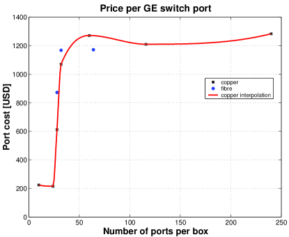
For a better bandwidth utilization the components having a low throughput can be grouped in clusters, using switches with a small number of FE or GE UTP ports and fibre GE up-links. Such concentrating switches are used for the ROBs and the L2PUs. The grouping reduces the size of the central switches significantly. The cost of the whole system goes down, as the “per port” price of small switches is at the moment much lower than that of large switches (see Figure 2).
The core of the network are the central switches (GE switches). The maximum number of central switches is dictated by the number of up-links of the ROB concentrating switches. The use of several central switches improves the fault tolerance of the network, and allows the implementation of various staging scenarios. The system shown in Figure 1 operates at full capacity when both its stages are active (the second stage is drawn in light colour). However, it can work at a lower rate using only one stage.
A stage contains two central switches: one for LVL2, and one for Event Building. The separation of the two data flows at an early stage can improve event processing latency for level 2 (replies to the LVL2 requesting nodes are not mixed with fragments directed to the EB), and aids the implementation of various Event Building traffic shaping schemes aimed at minimizing the packet loss probability .
II.3 Ethernet issues
For a proper operation of the ATLAS Baseline Architecture we need to investigate a series of Ethernet features:
-
•
switches performance: throughput, packet loss, latency, MAC (Media Access Control) address table size;
-
•
Flow Control behaviour at different levels of the network;
-
•
VLAN (Virtual Local Area Network) implementation;
-
•
QoS (Quality of Service);
-
•
broadcast and multicast handling.
The results obtained from investigating the above mentioned features, as well as their implication to the TDAQ system are the object of this paper, and will be presented in section III.
II.3.1 Why Ethernet?
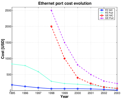
The reasons for using Ethernet technology for the DataFlow network are its high performance and the low price (see Figure 3). Ethernet products are now commodity. The technology is multi-vendor, and we foresee long term support for it.
The biggest step forward in the Ethernet evolution was the transition from half duplex CSMA/CD (Carrier Sense Media Access with Collision Detection) to full duplex. On a full duplex switched Ethernet network the bandwidth of each line is full time guarantied, allowing a successful use of Ethernet in real-time systems (as opposed to CSMA/CD, where the communication media is shared and access to it is not guaranteed).
Moreover Ethernet has an evolutionary upgrade path to high speed. The 10 GE (Gigabit Ethernet) IEEE standard was approved in 2002. For the moment the price of 10 GE Ethernet switches is high. However the expected price drop over the next few years would make them good candidates for the central switches.
III Ethernet features investigation
We have used our customized traffic generators (see BAR02 and DOB01 ) for testing the Ethernet Features required by the ATLAS Network-Based Architecture. The FE (Fast Ethernet) tester is a custom built board, designed at CERN. It implements 32 FE ports (full-duplex 100 Mbps) using Altera Flex FPGAs programmed in Handel-C. The GE tester is based on the Alteon Gigabit Ethernet NIC (Network Interface Card). The card uses the Tigon II PCI Ethernet Controller, which contains two customized MIPS CPUs, allowing a flexible reprogramming. We have 4 FE boards (thus 128 FE ports), and around 30 Alteon NICs.
The testers are capable of generating traffic with different packet sizes, either with a specified CBR (Constant Bit Rate) or with a Poisson (negative exponential) distributed inter-packet gap. They measure packet loss and latency (300 ns precision), and also histogram the latencies (jitter) on a per packet basis. For more details about the testers consult BAR02 .
We have used this equipment to test both concentrating and central switches from different manufacturers. By concentrating switches we denote switches with at least 2 GE optical fibre up-links and either many FE UTP (Unshielded Twisted Pair) or several GE UTP ports. The central switches have a large number of GE optical fibre ports (at least 30).
III.1 Basic measurements on switches
Switches are the key element of the ATLAS TDAQ Network-Based Architecture (see section II.2). They must meet the throughput requirements of the architecture with a minimum latency and packet loss.
Packet loss has a great penalty on the system’s performance, as it implies time outs and retries at the application level, which are time consuming. The switches drop frames when their buffers overflow, therefore the bigger the buffers, the smaller the probability of packet loss. The Ethernet Flow Control helps preventing buffer overflow, but it does not solve the packet loss problem completely (see section III.4).
We measure packet loss and latency for different Ethernet frame sizes, different loads (from 10% till 100% of the line speed), with CBR or with random (Poisson) inter-packet gap, using unicast, multicast and broadcast traffic.
The multicast and broadcast tests proved the handling of such traffic is vendor specific, and sometimes the maximum rate (throughput) is surprisingly low (less than 10% of the line speed). This is one of the reasons for choosing a preponderant request-response message flow scenario (unicast traffic) for the ATLAS Baseline Architecture (see section II.1).
(a)
 (b)
(b)
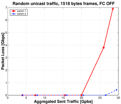
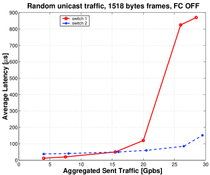
Figure 4 shows the results from a test performed on two different central switches, using 1518 bytes frames. We use 30 GE ports, each one sending unicast traffic to all the others with a negative exponential inter-packet gap. Switch 1 becomes saturated when the offered load exceeds 66% of the line speed. We first notice a slight increase of the latency followed by packet loss and a significant growth of the latency once the buffers become full. Switch 2 handles the traffic much better (almost line speed). All the switches from the ATLAS DataFlow network must operate below the saturation point, as packet loss and high latency values significantly diminish the overall system performance.
III.2 MAC address table size
The switch MAC address table contains the correspondence between the Ethernet MAC addresses and the switch’s ports associated to them. If the Ethernet destination address from the header of a received frame is not known by the switch, the frame will be forwarded through all its active ports (flooding). The DataFlow network has a large number of nodes (in excess to 2000), which must be memorized by the switches in order to minimize the flooding effect.
There are two types of MAC address table entries: static and dynamic. Static entries are entered using a switch management tool. This ensures that the switch will never flood frames. However, if the network topology changes the user needs to update the MAC address table. This is a great inconvenience for networks with large number of nodes. On the other hand no human intervention is needed if we use dynamic entries. When a frame is received, the switch looks at its Ethernet source address. If the address is unknown to the switch, it is added to the MAC address table. If the network topology changes and the same MAC address is received on a different port, the MAC table will be updated correspondingly. When the switch no longer receives frames from an address for a certain amount of time (aging time), it will erase that entry from the MAC address table. A typical value for the aging time is some hundreds of seconds. This is another motivation for the request response traffic. We want to operate the DataFlow with dynamic MAC address table entries, and the request-reply scenario minimizes the probability of aging.
In order to test the MAC address table size we have modified the Alteon traffic generators. We have created a client which can generate up to 4096 MAC addresses with different patterns. This client sends requests to the switch. Two more NICs are set in promiscuous mode (they will receive all the frames arriving to them, regardless of their Ethernet destination address). One of them is used as a server which responds using the destination address from the received request as its own Ethernet source address. This “server” will emulate any number of Ethernet nodes. The second NIC which is set in promiscuous mode is used as a “listener” for flooding. We first perform a learning phase: after clearing the switch MAC address table, we generate 4096 requests with different Ethernet destination addresses. The switch does not know anything about them so it will flood them on all the ports. Both the listener and the server will see them all. The server replies will allow the switch to learn the injected Ethernet addresses. Subsequently we run the measurement phase: we clear the counters both on the server and the listener, and then repeat the generation of the same 4096 requests. Let denote the number of frames received by the listener node during the measurement phase. The listener should see only the flooded frames, i.e the ones corresponding to the addresses not learned by the switch. Therefore we are sure that the switch can accommodate MAC addresses in its table.
We have applied this method for different MAC address patterns on several switches. Table 1 summarizes the results from a switch with a peculiar behaviour. If we linearly increase the lower two bytes of the MAC address, while keeping the others fixed (line 1) the switch learns 4096. The same thing happens when we randomly generate the lower three bytes (line 4), or when we mix the linear and random patterns (line 5). The unexpected behaviour is revealed when we linearly increase either the fourth and the fifth bytes (line 2), or the third and the fourth (line 3): the switch MAC address table size is less than 80.
| MAC address pattern | MAC address table size |
|---|---|
| 00:xx:yy:zz: | 4096 |
| 00:xx:yy::zz | 70 |
| 00:xx::yy:zz | 80 |
| 00:xx:yy: | 4096 |
| 00:xx:yy: | 4096 |
| 00:xx:yy:zz: |
All the nodes from the DataFlow network except the ROBs are interfaced via standard NICs. The MAC address of a NIC has the manufacturer code reflected in the first four bytes, while the last two bytes of the address are most likely random. This address pattern (line 4 from table 1) causes no problem to the switch. The ROBs are custom build hardware, and we have the freedom of choosing their HW addresses. It is natural to linearly increase two of the bytes from the MAC address. Our measurements show that for a proper operation of this particular switch we are forced to vary the lower two bytes of the MAC address. When choosing the ROB MAC addresses we must also make sure the first four bytes do not coincide with any manufacturer code.
III.2.1 MAC address aging
The MAC address aging time should be large enough to avoid flooding once the DataFlow system is operating. In the request-response message flow scenario all the nodes send messages to the network periodically. At the level of ROB switches and Central switches the SFI Event Building has the lowest rate (around 30 Hz), which imposes an aging time larger than 30 ms. The aging time in the switches we have tested is typically some hundreds of seconds, therefore more than enough at this level of the network. Yet flooding may potentially occur in the L2PU switches. These switches never forget the addresses of the L2PUs (which request with an average rate of 10KHz), but they may forget the addresses of some ROBs. L2PUs receive data only from a fraction of the ROBs and there is a low probability that an L2PU cluster does not request data from a given ROB for a period larger than the aging time. This probability is fairly low, and the flooding has a small impact, as it will most likely be confined to that concentrating switch.
Thus a typical value of hundreds of seconds for the MAC address table aging time assures a proper packet switching (no flooding after the beginning of the run) in the DataFlow network.
III.3 VLANs – IEEE 802.1Q
The extended header of the Ethernet frame may include a VLAN (Virtual LAN333Local Area Network) tag immediately after the Ethernet addresses. This tag contains the VLAN ID (identifier), and also a priority field. The VLAN ID allows more logical (virtual) LANs to coexist on the same physical LAN, while the priority field allows the layer two traffic to be classified. VLANs are crucial for the ATLAS Network-Based Architecture, as they assure a loop free topology. In addition they bound the multicast/broadcast messages, and provide QoS (Quality of Service) support.
III.3.1 Loops and the Spanning Tree Protocol.
The network topology of the ATLAS Network-Based Architecture (Figure 1) contains loops. An example of a loop is the LVL2 central switch – a ROB concentrating switch – the EB central switch – another ROB concentrating switch. Ethernet loops are illegal because they perturb the MAC address tables for unicast traffic and they keep sending forever multicasts and broadcasts (broadcast storms). The STP (Spanning Tree Protocol) is designed to cut off the redundant links from a LAN in order to maintain a loop free topology. We plan to use VLANs for maintaining a loop free topology: a LVL2 VLAN (for the level 2 traffic) and an EB VLAN (for the Event Building data flow). Several nodes need to be part of both VLANs: the DFM, the PROB and the ROBs.
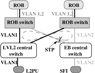
The setup described in Figure 5 allows us to verify that VLANs eliminate illegal loops, and also to check if the STP is aware of VLANs. The tests performed showed that VLANs provide a loop free topology when the STP is disabled. When the STP was active, it disabled one of the links in the loop. This is due to the fact that the STP is not implemented per VLAN on those switches.
We have full control over the DataFlow network. Therefore, if the STP is not implemented per VLAN we can disable it, and carefully use VLANs for maintaining a loop free topology.
III.3.2 Traffic containment
VLANs keep flooding, multicast and broadcast traffic inside their defined bounds. To verify this feature we use one transmitter and several receivers. The transmitter sends traffic to the investigated VLAN (unicast to an address which is not known by the switch, multicast or broadcast). We place one receiver in every VLAN which is defined on the switch, plus an additional receiver outside any defined VLAN (i.e in the switch’s default VLAN). All receivers outside the VLAN into which we inject traffic should receive no frames.
We have carried out such tests for several switches in all of the following situations: one VLAN, two VLANs with no shared ports and two VLANs with shared ports. In no case were the VLAN boundaries crossed.
This feature is useful as we can restrict the number of nodes receiving a multicast/broadcast message. For example, if we define a third VLAN in the DataFlow network, containing the DFM and the ROBs, the clear message multicasted by the DFM will be forwarded only to the nodes it should reach (i.e. the ROBs).
III.3.3 Partitioning
VLANs divide a physical LAN into more logical ones. By analogy we want to see if VLANs can partition one physical switch in two logical ones, and also quantify the interference between the two partitions.

In the setup presented in Figure 6 we send independent traffic into each of the two VLANs which do not share ports. For several traffic loads in VLAN2 we measure the behaviour inside VLAN1. For the switch we have tested the performance inside VLAN1 is insensitive to the amount of traffic flowing through VLAN2. Therefore this switch can be partitioned in a satisfactory way using VLANs. This feature is highly dependent on the switch architecture, and no assumption should be made a priori for any switch.
III.3.4 Quality of Service (QoS)
Quality of Service support is provided by the priority field from the VLAN tag. Up to eight different priorities can be assigned to the frames, as the priority field is three bits wide. Switches may adopt different QoS schemes such as strict priority or weighted round robin (WRR). If the line is oversubscribed the latter algorithm allocates bandwidth for all the priorities proportionally to their associated weight.
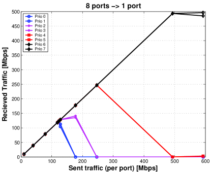
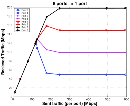
Figure 7 presents the results of a QoS test. Eight GE ports send constant bit rate (CBR) traffic (1518 bytes frames) to the same GE receiving port. Each of the senders sets a different priority in the VLAN tag. Once the intended throughput exceeds the line capacity the strict priority algorithm gradually starves the lower priorities in favor of the higher ones. In the case of the WRR algorithm the bandwidth is allocated to each priority proportionally to its associated weight, once the line is saturated.
(a)
 (b)
(b)
A possible use of QoS in the DataFlow is to assign a higher priority to the control messages (like the messages from the L2SV to the DFM) with respect to the main data flow.
III.4 Ethernet Flow Control
On a full duplex Ethernet line, a slow receiver can limit the sending rate of a fast transmitter, using Ethernet Flow Control Frames. The FC (Flow Control) mechanism is presented in Figure 8. When the receiver becomes low in resources it sends a PAUSE frame, which will block the transmitter. Once enough resources are available on the receive side a RESUME (transmission) frame tells the transmitter to restart sending the data stream.
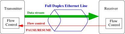
A proper Ethernet Flow Control implementation guarantees no overflow occurs at the level of Ethernet MAC buffers. Yet we must investigate Flow Control propagation through the network switches, as well as inside the PC’s (NIC, Operating System (OS) and user-level application), in order to efficiently use this feature in the ATLAS TDAQ system.
III.4.1 Propagation through the switches
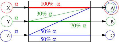
In the setup illustrated in Figure 9 all the transmitters send CBR traffic at the same rate, denoted as . X sends 100% of entirely to A, Y splits its traffic 30% to A and 70% to B, while Z transmits 50% to A and 50% to C. We gradually increase up to the line speed. When becomes larger than 56% of the line speed the switch port from node A is oversubscribed.
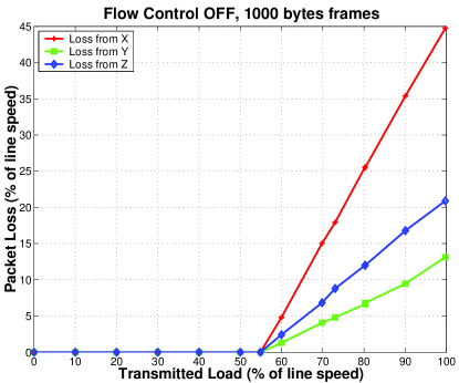
When Flow Control is disabled on all the ports, packet loss occurs at the congested port (Figure 10 (a)). It is important to see if the congested port affects the other traffic paths. Although some of the frames directed to A are lost, B receives all the traffic from Y without any loss. The same observation is true for transmitter Z. This proves the input buffers have separate queues for each outgoing port, therefore the switch is not susceptible to HOL (Head Of Line) blocking.
(a)
 (b)
(b)
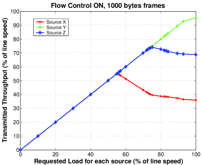
Once we enable Flow Control (both on the nodes and the switch’s ports) we no longer observe packet loss at port A. This proves the switch is propagating Flow Control between its ports ensuring a lossless frame transfer between the input and output switch buffers. The price paid for no packet loss is the congestion spreading effect. The congestion from port A causes a slowdown in the transmission rate of all the ports that send frames to this destination (X, Y and Z). Thus the sending rate from Y to B, as well as from Z to C will be affected. Figure 10 (b) demonstrates that the congestion effect from port A spreads towards all the ports contributing to it proportionally with the amount of traffic sent to the oversubscribed port.
The congestion spread caused by the choice of propagating Flow Control through the switch has undesired effects in case of a node failure. We have modified the A receiver to emulate a “dead” node with active FC444This may happen if the Linux kernel crashes but the PC’s NIC remains active, or if the firmware crashes on a hardware device like the ROBs. As the “dead” node cannot empty the received frames from the low level MAC receive queue, it will keep sending FC to the switch, as long as the latter tries to deliver packets to node A. The congestion spreads, and all the transmitters are completely blocked. No traffic reaches port B or C, as long as Y and Z keep sending towards A. Therefore, it will be important to detect and deal with malfunctioning network nodes.
The choice of propagating Flow Control through the switches is manufacturer depended. Some switches do not propagate FC. Packet loss occurs if the congestion cannot be absorbed by the internal switch buffers. However, in this case there is no congestion spreading effect.
III.4.2 User level application – traffic shaping
One may think that building a network with switches that propagate FC (and enabling it everywhere) guarantees lossless communication between all the applications. This is not true if the applications run on Linux OS PCs. We use one PC with a request-response program emulating the SFI functionality, while the ROBs are emulated by modified traffic generators (see Figure11).
In order to see if the PC sending rate can be reduced by Flow Control, the SFI interrogates only one ROB, which is artificially slowed down using a busy loop. The ROB cannot cope with the request rate, asserts FC which propagates through the network, and slows down the PC’s NIC. The kernel sending queues will fill up and a call to send will fail. If the errno (a global variable indicating the error encountered while executing the send system call) value indicates no buffer space was available for sending, the sending thread should sleep for a while, then try to send again. Therefore the PC sending rate can be reduced using Flow Control.
On the receive part the things are not that simple. If the PC’s NIC or kernel cannot cope with the received traffic rate, FC will be asserted by the NIC. The problem appears when the user-level application cannot empty its communication socket receive buffer. If the kernel cannot push frames to the application’s socket receive buffer, it will simply drop them without any further notice. In other words, a lazy user level application is not allowed to slow down (or even block) other peer processes which use different communication sockets. On the other hand this kernel behaviour limits the user-level application’s ability to assert Flow Control when it cannot cope with the incoming message rate.
Thus it is important that the DataFlow applications use a request-response message flow scenario. Each node can take care not to request more than it is prepared to receive: traffic shaping. The sending part of an application is blocked if the number of outstanding request exceeds a certain threshold, and becomes active once responses arrive back.
III.5 Trunking (LAG - Link Aggregation Group) – IEEE 802.3ad
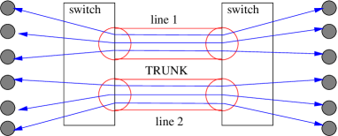
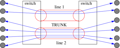
Trunking allows grouping more physical links in order to form one logical link with a higher bandwidth. The IEEE standard specifies that the order of Ethernet frames shall aways be preserved by the trunk. Though, there’s no restriction for the allocation of the frames to the physical lines within the trunk.
Once a physical link is associated to a pair of MAC addresses, all the frames addressed to any of them will go on that link until the switch forgets about one of the two MAC addresses (due to aging). This leads to a potential load balancing problem. Figure 12 (a) shows an even distribution of the traffic, while Figure 12 (b) reveals an uneven distribution of the traffic on the lines withing the trunk.
(a)
(b)
We will further use the term “connection” to denote a pair of MAC addresses, each one located on a different side of the trunk. The particular switches we have tested randomly allocate the physical links (within the trunk) to a connection, regardless of the traffic amount. In Figure 12 (b) it may happen that the upper link of the trunk is not utilized, while the lower one is oversubscribed.
From the ATLAS point of view, all the nodes from one side of the trunk will require a similar bandwidth. Considering there will be a large number of connection pairs (there are approximately 1600 ROBs) across the trunk, a random allocation algorithm will be effective, if we decide to use trunks in the DataFlow network.
IV Conclusions
Ethernet is considered the most suitable technology for the DataFlow network because:
-
•
It satisfies the bandwidth requirements for the ATLAS DataFlow.
-
•
Segments with different speeds can be transparently interconnected via switches: 100 Mbps, 1 Gbps and 10 Gbps.
-
•
It is multi-vendor technology with long term support.
-
•
Ethernet is a commodity:
-
–
The price of the GE UTP NIC is approximately 80 USD. However, most high-end PCs are equipped with an on-board GE NIC.
-
–
The GE switch port cost is constantly dropping with time.
-
–
-
•
PCs have become fast enough to cope with the Gigabit Ethernet line speed. A dual Pentium 4, with a CPU frequency of 2.4 GHz, can receive approximately 70 MBytes/second, in a request–reply traffic scenario for Event Building.
-
•
Ethernet has an evolutionary upgrade path to high speed.
The DataFlow network must be a high performance network, as its nodes run real-time applications. That’s why the Ethernet features presented in this article must be verified on every switch before its integration to the network.
Acknowledgements.
The authors wish to express their gratitude to:-
•
Razvan Beuran and Mihail Ivanovici for the QoS measurements;
-
•
Catalin Meirosu and Jamie Lokier for developing the GE network tester;
-
•
Micheal LeVine, Jamie Lokier and Razvan Beuran for developing the FE network tester.
References
- (1) DF, The atlas tdaq dataflow community, http://atlas.web.cern.ch/Atlas/GROUPS/DAQTRIG/DataFlow/DFlowAuthors.pdf555M. Abolins, A. Dos Anjos, M. Barisonzi , H. Beck, M. Beretta, R. Blair, J. Bogaerts, H. Boterenbrood, D. Botterill, M. Ciobotaru, E. Palencia Cortezon, R. Cranfield, G. Crone, J. Dawson, B. DiGirolamo, R. Dobinson, Y. Ermoline, M.L. Ferrer, D. Francis, S. Gadomski, S. Gameiro, P. Golonka, B. Gorini, B. Green, M. Gruwe, C. Haeberli, Y. Hasegawa, R. Hauser, C. Hinkelbein, R. Hughes-Jones, P. Jansweijer, M. Joos, A. Kaczmarska, G. Kieft, K. Korcyl, A. Kugel, A. Lankford, G. Lehmann, M. LeVine, W. Liu, T. Maeno, M. Losada Maia, L. Mapelli, B. Martin, R. McLaren, C. Meirosu, A. Misiejuk, R. Mommsen, G. Mornacchi, M. M ller, Y. Nagasaka, K. Nakayoshi, I. Papadopoulos, J Petersen, P. de Matos Lopes Pinto, D. Prigent, J. Schlereth, M. Shimojima, R. Spiwoks, S. Stancu, J. Strong, L. Tremblet, J. Vermeulen, P. Werner, F. Wickens, Y. Yasu, M. Yu, H. Zobernig, M. Zurek.
- (2) H. Beck, B. Dobinson, K. Korcyl, and M. Levine, DC note 059 (2003), http://atlas.web.cern.ch/Atlas/GROUPS/DAQTRIG/DataFlow/DataCollection/docs/DC-059/DC-059.pdf.
- (3) H. Beck and F. Wickens, Data Collection note 012 (2002), http://atlas.web.cern.ch/Atlas/GROUPS/DAQTRIG/DataFlow/DataCollection/docs/DC-012/DC-012.pdf.
- (4) F. Barnes, R. Beuran, R. Dobinson, M. J. LeVine, B. Martin, J. Lokier, and C. Meirosu, “Testing Ethernet Networks for the ATLAS Data Collection System”, in IEEE Trans. on Nuclear Science (IEEE Nuclear and Plasma Sciences Society, 2002), vol. 49, No. 2, p. 516.
- (5) R. Dobinson, S. Haas, K. Korcyl, M. J. LeVine, J. Lokier, B. Martin, C. Meirosu, F. Saka, and K. Vella, “Testing and Modeling Ethernet Switches and Networks for Use in ATLAS High-level Triggers”, in IEEE Trans. on Nuclear Science (IEEE Nuclear and Plasma Sciences Society, 2001), vol. 48, No. 3, pp. 607–612.