Differential Methods in Catadioptric Sensor Design with
Applications to Panoramic Imaging
Technical Report
Abstract
We discuss design techniques for catadioptric sensors that realize given projections. In general, these problems do not have solutions, but approximate solutions may often be found that are visually acceptable. There are several methods to approach this problem, but here we focus on what we call the “vector field approach”. An application is given where a true panoramic mirror is derived, i.e. a mirror that yields a cylindrical projection to the viewer without any digital unwarping.
1 Introduction
A fundamental problem of imaging is the creation of wide-angle and panoramic images. Wide-angle images that do not have radial distortion require complex assemblies of lenses, because as the field of view increases, abberations are introduced, which in require the addition of more lenses for correction. Fish-eye lenses offer wide-field of views but at the cost of considerable radial distortion. This distortion may be removed in software, but the resulting images suffer from poor resolution in some regions.
Panoramic images present a related challenge. A straightforward, yet tedious approach is the stitching together of images. In the 19th century numerous cameras were created for taking panoramic still shots through ingenious rotating mechanisms (e.g. rotating slit cameras), but were inherently awkward. Adapting such devices for digital imaging (especially video applications) is clearly problematic.
The introduction of a curved mirror into a conventional imaging system is an elegant solution to these problems. General design questions are:
A. How does one design a catadioptric sensor to image a prescribed region of space ?
B. How does one design a catadioptric sensor to maximize image quality ?
C. How does one design an optimal catadioptric sensor for a given machine vision application, such as robot navigation, tracking or segmentation ?
Commercial interest in panoramic sensors based on these ideas has risen sharply in the last five years, and a large number of companies have emerged to to meet the demand. Common commercial applications are surveillance and “virtual tours” on the web. At last count, at least 19 different companies were found offering panoramic sensors for sale, the majority of which were based on catadioptrics (see [4]).
2 Related Work
2.1 Rotationally Symmetric Mirrors
Almost all research performed with mirrors refers to rotationally symmetric mirrors, since these mirrors are the simplest to make and to mathematically model. For every curve in the plane, one may create a mirror by rotating the curve about a chosen line, which will then play the role of the optical axis. Clearly then, there are an infinite number of possible mirrors and the question then is which one to choose for a given application. This generally gives rise to the problem of finding a mirror shape given a prescribed property. To do this generally amounts to solving a differential equation. For example, if one requires a curve that focuses parallel rays, the answer is a parabola. In this case, the curve and it’s special property are familiar and differential methods are not needed, but this is a rare exception.
An early use of mirrors for panoramic imaging is a patent by Rees [12], who proposes the use of a hyperbolic mirror for television viewing. Another patent is by Greguss [6], which is a system for panoramic viewing based on an annular lens combined with mirrored surfaces.
Early applications to robotics using a conical mirror were carried by Yagi et al. in [13]. Yamazawa et al [14] use a hyperbolic mirror for obstacle detection.
In [10], Nayar describes an omnidirectional sensor from which it is possible to create perspective views by unwarping the images in software. In order to do this, the sensor must satisfy the single viewpoint constraint, which means that the sensor only measures the intensity of light passing through some fixed single point in space. This sensor uses a parabolic mirror, which, remarkably, is the only shape from which one can achieve a perspective unwarping of the image when using an orthographic camera (see [1]).
The first use of differential methods for design was by Chahl and Srinivasan in [2]. Here the authors employ differential methods to derive a mirror shape such that the radial angle and the angle of elevation (see figure (1)) are linearly related.

In [11], Ollis et al. argue that improved resolution uniformity is obtained if one demands that the angle of elevation be proportional to the tangent of the radial angle ; geometrically, represents the distance of the image point to the optical axis. Thus, as the angle ”sweeps” out some range of angle, a proportional length is swept out in the image plane (note that the line of reasoning here is essentially one dimensional). The authors then apply these mirrors to mobile robot navigation and panoramic stereo.
A variant of the Ollis mirror is described by Conroy and Moore in [3]. Using the same parameters as above, the authors then calculate what the mirror shape such that is proportional to the area of the corresponding disk in the image plane.
Hicks and Bajcsy derive the mirror shapes for a sensor in [7] which will give wide-angle perspective images, and so uniformly image planes. In [9] Hicks and Perline describe a sensor for which the projection map from the view sphere to the image plane is area preserving. This means that any two solid angles are allocated the same number of pixels by the sensor.
Sensors designed to image cylinders were investigated by Gaechter and Pajdla in [5]. The analysis of these devices is essentially two dimensional and extended to three dimensions by radial symmetry. In fact, the unwarping map (corresponding to a cylindrical projection) for these sensors is the standard polar map.
2.2 The Asymmetric Case
If one leaves the realm of rotational symmetry, the problem of constructing a mirror for a given projection gets significantly more difficult. Not only are the equations much more complex, but with probability 1 they will not have solutions.
In [8] this problem is addressed and methods for approximating solutions are introduced. Here we extend this work and give a new application.
3 Problem Statement
We work under the assumption that all cameras realize perfect perspective or orthographic projections.
Suppose one is given a fixed surface in and a camera with image plane , also fixed in . A given mirrored surface induces a transformation from some subset of to by following a ray from a point until it intersects the mirror at a point . The ray is then reflected according to the usual law that the angle of incidence is equal the angle of reflection and intersects at a point . We then define .
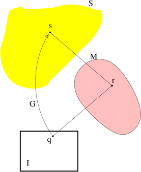
The general problem is:
Given , find such that . If no such exists, then find such that is a good approximation to .
Figure (2) is a corresponding diagram. If an exact solution exists, then there are several ways to calculate it. Otherwise, there are numerous ways to formulate and solve the approximation problem. Below we briefly discuss three of these approaches - the fixed surface method, the vector field method, and the method of distributions . If the problem does not have a solution, then each formulation gives rise to many possible choices of approximation techniques.
3.1 The Fixed-Surface Method
In this method, one assumes that a generic is given in some coordinates and then from it calculate . If one represents as a graph then the expression for will contain partial derivatives of . Thus the problem of finding such that is reduced to the problem of simultaneously solving a system of partial differential equations. This is the approach introduced in [8].
3.2 The Vector-field Method
Notice that for a given , with and as above, that the vector is normal to at . This suggest a method of constructing a vector field on that will be normal to the solution: for each define
| (1) |
where is the point in the image plane corresponding to (i.e. rays traced out from contain ). If exists and is expressed as a level surface , then there will be a scalar function s.t.
| (2) |
In fact, several necessary and sufficient condition exist for testing for the existence of from . For example, exists iff .
3.3 The Method of Distributions
In the above vector field formulation clearly as defined is only parallel to and not generally equal to it. Thus the underlying structure of importance is the planar distribution that is orthogonal to . Hence another formulation of the problem is to find an integral surface of the distribution (which is, of course, defined in terms of ). This may be then phrased as a variational problem, which may be attacked directly with numerical methods or one may consider the corresponding Euler-Lagrange equations. We will not discuss this method any further or give any examples here.
4 Analog Panoramic Imaging
The projection we are interested in mimicking with a mirror is the so-called cylindrical projection, in which the world is first projected onto a cylinder, which is the cut and rolled open, giving a panoramic “strip” (which for our purposes will lie in ). The resulting strip can be thought of as having coordinates and where the coordinate varies from to or some equivalent interval. Of course we cannot realize this projection exactly, since it has a single projection point, but we can approximate it very well.
We take as our object surface a cylinder whose axis of symmetry coincides with the optical axis of our camera, which we assume realizes an orthographic projection. This will allow us to apply the vector field approach. Despite the fact that we will use the vector field described above, and not attempt to find an optimal , the result is visually acceptable.
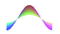
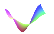
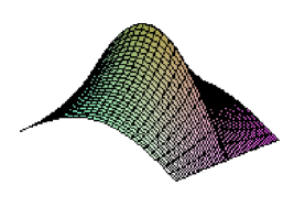
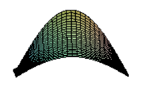
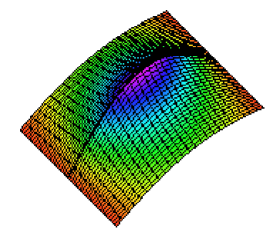
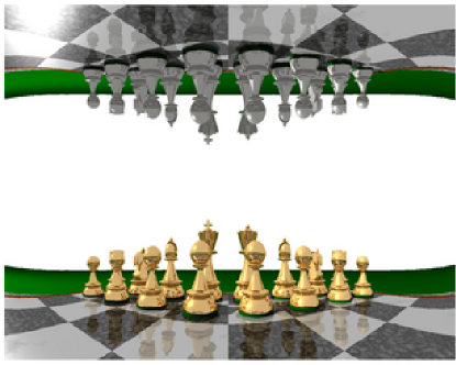
In figure (3) appears three views of a mirror that has this property. This mirror provides a degree view in the vertical and a full 360 degree view in the horizontal. In figure (4) we see this surface used to image a chess board. To achieve this view the mirror is placed in the middle of the board (at approximately the height of the king’s head) and viewed from below.

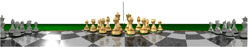
Possible advantages of using a panoramic mirror of the above type over existing systems are that this sensor would not require a digital computer for unwarping, and that by performing the unwarping prior to the sampling of the image, the resolution of the image is more uniform.
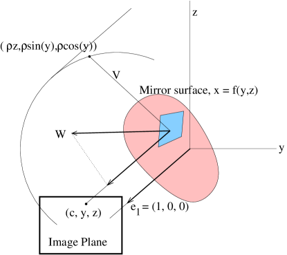
To find the above surface, we take the image plane, , to be of the form , so the optical axis is the -axis. The surface is taken to be a cylinder of radius about the -axis. The vector field is derived as follows. According to our above formulation, , and . ( plays the role of and the role of ). At the incident ray of light should be in the direction where
| (3) |
(See figure (5).) Normalizing and letting gives the unit vector
| (4) |
Then , i.e.,
| (5) |
Since we are free to scale as we see fit and , a natural choice is to scale by the inverse of the first component of , in which case the resulting vector field is
| (6) |
Thus the problem is to find a function whose gradient is as close to as possible. Clearly there are different notions of closeness, but a very natural solution is to take and and then take to be the minimizer of
| (7) |
where is a region in the plane corresponding to the portion of th image plane that is of interest (the panoramic strip)111This is closely related to the Hodge decomposition theorem, which states that every vector field may be orthogonally decomposed into an exact vector field plus a vector field with zero divergence. The proof boils down to considering Poisson’s equation with known boundary conditions, and so existence and uniqueness is easily established. This provides an alternative computational approach to the problem.. Presumably though we wish the width of to be at least in order to get a panoramic image. The component will control to vertical field of view. The above integral was minimized in Maple by taking was to be a generic polynomial in and of fixed degree. Notice that the surface used in the ray tracing examples above was derived taking , and yet it works well for “close” objects - the mirror itself was approximately the size of a chess piece.
Finally, the above sensor can be altered to fill an entire 640 by 480 video image entirely. In figure (6) we see several images of a mirror constructed by taking the union of the section of the above mirror corresponding to with its reflection, resulting a shape reminiscent of a conquistador helmet. This means that all the pixels of the video camera are being used to create the panoramic image. Compared with rotationally symmetric systems these lead to a 70 % increase in image resolution. Figure (7) shows the chess board using this mirror.
References
- [1] S. Baker and S. Nayar. A theory of catadioptric image formation. In Proc. International Conference on Computer Vision, pages 35–42, 1998.
- [2] J.S. Chahl and M.V. Srinivasan. Reflective surfaces for panoramic imaging. Applied Optics, 36:8275–8285, 1997.
- [3] T. Conroy and J. Moore. Resolution invariant surfaces for panoramic vision systems. In Proc. International Conference on Computer Vision, pages 392–397, 1999.
- [4] K. Daniilidis. The page of omnidirectional vision, http://www.cis.upenn.edu/ kostas/omni.html, 2002.
- [5] S. Gaechter and T. Pajdla. Mirror design for an omnidirectional camera with space variant imager. In Proc. of the Workshop on Omnidirectional Vision Applied to Robotic Orientation and Nondestructive Testing (NDT), Budapest, 2001.
- [6] P. Greguss. Panoramic Imaging Block for Three-dimensional space. United States Patent, (4,566,736), January, 1986.
- [7] R. A. Hicks and R. Bajcsy. Catadioptic sensors that approximate wide-angle perspective projections. In Proc. Computer Vision Pattern Recognition, pages 545–551, 2000.
- [8] R. A. Hicks and R. Perline. Geometric distributions and catadioptric sensor design. In Proc. Computer Vision Pattern Recognition, pages 584–589, 2001.
- [9] R. A. Hicks and R. Perline. Equi-areal catadioptric sensors. In Proc. of IEEE Workshop on Omnidirectional Vision, pages 13–18, 2002.
- [10] S. Nayar. Catadioptric omnidirectional camera. In Proc. Computer Vision Pattern Recognition, pages 482–488, 1997.
- [11] M. Ollis, H. Herman, and Sanjiv Singh. Analysis and design of panoramic stereo vision using equi-angular pixel cameras. Technical Report, The Robotics Institute, Carnegie Mellon University, 5000 Forbes Avenue Pittsburgh, PA 15213, 1999.
- [12] D. Rees. Panoramic television viewing system. United States Patent, (3,505,465), April, 1970.
- [13] Y. Yagi and S. Kawato. Panoramic scene analysis with conic projection. In Proceedings of the International Conference on Robots and Systems, 1990.
- [14] K. Yamazawa, Y. Yagi, and M. Yachida. Omnidirectional imaging with hyperboidal projection. In Proceedings of the IEEE International Conference on Robots and Systems, 1993.