On the Complexity of Buffer Allocation in Message Passing Systems
Abstract
Message passing programs commonly use buffers to avoid unnecessary synchronizations and to improve performance by overlapping communication with computation. Unfortunately, using buffers makes the program no longer portable, potentially unable to complete on systems without a sufficient number of buffers. Effective buffer use entails that the minimum number needed for a safe execution be allocated.
We explore a variety of problems related to buffer allocation for safe and efficient execution of message passing programs. We show that determining the minimum number of buffers or verifying a buffer assignment are intractable problems. However, we give a polynomial time algorithm to determine the minimum number of buffers needed to allow for asynchronous execution. We extend these results to several different buffering schemes, which in some cases make the problems tractable.
keywords:
Message passing systems , Buffer allocation , Complexity , Parallel and distributed programming, ,
1 Introduction
In the last decade MPI [8] and PVM [14] have become the de facto standards for message passing programs. They have replaced the myriad of libraries that provided a degree of portability for message passing programs. One aspect of portability introduced in the MPI standard was that of a safe program. As defined in the standard, a program is safe if it requires no buffering, that is, if it is synchronous. Safe programs can be ported to machines with differing amounts of buffer space. However, to demand that the program execute correctly with no buffering is restrictive. Buffering reduces the amount of synchronization delay and also makes it possible to off-load communication to the underlying system or network components, thus overlapping communication and computation. Although one cannot assume an infinite number of buffers, by characterizing the buffer requirements of a given program it becomes possible to determine, with respect to buffer availability, whether the program can be ported to a given machine. The notion of -safety is introduced to address the problem of identifying the buffer requirements of a program to avoid buffer overflows and deadlock. Determining the minimum , under a variety of buffer placements, is important for constructing programs that are both safe and can effectively exploit the underlying hardware.
Unfortunately, the value of is usually not known a priori. We investigate the complexity of determining a minimum value of for programs using asynchronous buffered communication with a static communication pattern and a bounded message size. We consider the following three problems: the Buffer Allocation Problem (BAP), which is the problem of determining the minimum number of buffers required to ensure deadlock free execution (i.e., determine for -safety); the Buffer Sufficiency Problem (BSP), which is to determine whether a given buffer assignment is sufficient to avoid deadlock; and finally, the Nonblocking Buffer Allocation Problem (NBAP),which is to determine the minimum number of buffers needed to allow for asynchronous execution, that is, when send calls do not block.
The complexity of these questions also depends on the type of buffers provided by the system. We consider four types of system buffering schemes. In the first three schemes the buffers are (1) pre-allocated on the send side only, (2) the receive side only, or (3) mixed and pre-allocated on both sides. Finally, we also consider a scheme that pre-allocates buffers on a per channel basis, where each communication channel can buffer a fixed number of messages.
We show that the Buffer Allocation Problem is intractable under all four buffer allocation schemes. The Buffer Sufficiency Problem is intractable for the receive side buffer and for the mixed buffer allocation schemes, tractable for the channel scheme and conjectured tractable for sender side buffers. Finally, the Nonblocking Buffer Allocation Problem is tractable for all buffer placement schemes, except the mixed send and receive scheme.
2 Related Work
The multiprocess system that we consider is a collection of simultaneously executing independent asynchronous processes that compute by interspersing local computation and point-to-point message passing between processes; these are referred to as A-computations in [4]. Such a system is equivalent to one with three different events, such as the one defined by Lamport [18]: send events, receive events and internal events. As well, we only consider programs that are repeatable [6, 7] when executed in an unrestricted environment, that is, programs with static communication patterns. While this narrows the class of programs we consider, the class of applications with static communication patterns is still considerable.
The message passing primitives considered in this paper are the traditional asynchronous, buffered communications: the nonblocking send and the blocking receive, which are the standard primitives used in MPI and PVM. Cypher and Leu formally define the former as a POST-SEND immediately followed by a WAIT-FOR-BUFFER-RELEASE and the latter as a POST-RECEIVE immediately followed by a WAIT-FOR-RECEIVE-TO-BE-MATCHED [6, 7]. Informally, the send blocks until the message is copied out of the process into a send buffer; the receive blocks until the message has been copied into the receive buffer.
The notion of safety, as introduced in the MPI standard, underscore the concern that, when buffer resources are unknown, asynchronous communication can potentially deadlock the system. This notion was extended to -safety, in order to better characterize the buffer requirements of the program, thus making it safe to take advantage of asynchronous communication. The definition of -buffer correctness was introduced by Bruck et al. [2] to describe programs that complete without deadlock in a message passing environment with buffers per process. Similarly, Burns and Daoud [3] introduced guaranteed envelope resources into LAM [12], a public domain version of MPI. Guaranteed envelope resources—a weaker condition than -safety—was used in LAM to reserve a guaranteed number of message header slots on the receiver side.
Determining whether a system is buffer independent—the system is 0-safe—was investigated in [6, 7]. In our model, the interesting systems are buffer-dependent, and require an unknown number of buffers to avoid deadlock.
More recently in modern clusters, greater overlap of computation and communication is possible by off-loading communication onto the network interface cards. Unfortunately, most NICs have orders of magnitude less memory than the average host, which makes message buffers a limited resource. Thus, programs that use asynchronous message passing, and that execute correctly otherwise, might deadlock when executing on a system where parts of the message passing system have been off-loaded to the NIC. These issues have been investigated in several papers [8, 9, 11, 17].
To determine the minimum number of buffers, the execution of a system can be modeled using a (coloured) Petri net [16]. In order to determine whether the system can reach a state of deadlock, the Petri net occurrence graph [15] is constructed, and a search for dead markings is performed. However, the size of the occurrence graph is exponential in the size of the original Petri net.
Variations of these problems have been investigated by the operations research community [1, 20, 21]. In these models, events or products are buffered between various stations in the production process, however, the arrival of these events is governed by probability distributions, which are specified a priori. In our model, since processes are asynchronous, the time for a message to arrive is non-deterministic; that is, a message may take an arbitrarily long time to arrive and a process may take an arbitrarily long time to perform a send or a receive.
3 Definitions
Let be a multiprocess system with processes and communication events occurring in process ; a communication event is either a send or a receive. A multiprocess system is unsafe if a deadlock can occur due to an insufficient number of available buffers; if is not unsafe, then is said to be safe. Figure 1 is an example of an unsafe system. The numbers above the graph in Figure 1 represent the buffer assignment.

A per-process buffer assignment is an -tuple of non-negative integers representing the number of buffers that can be allocated by each process. Similarly, a per-channel buffer assignment is a -tuple , , representing the number of buffers each channel in the system can allocate. Since buffers take up memory, which may be needed by the application, ideally, as few buffers as possible should be allocated. However, allocating too few buffers results in an unsafe system.
Buffer utilization is the nondeterministic phenomena of interest in the system. Making the choice of when to use a buffer affects future choices. For example, in Figure 1, using a buffer for communication before communication 3 completes results in deadlock.
Two natural decision problems arise from this optimization problem. Given a system and a non-negative integer , the Buffer Allocation Problem (BAP) is to decide if there exists a buffer assignment such that is safe and . In order to solve this problem we need to solve a simpler one. Suppose we are given a buffer assignment and a system ; the Buffer Sufficiency Problem (BSP) is then to decide whether the assignment is sufficient to make safe.
Additionally, we can require that no process in system should ever block on a send. Given a system and a non-negative integer , the Nonblocking Buffer Allocation Problem (NBAP) is to decide whether there exists a buffer assignment , such that no send in ever blocks, and .
We model systems by using communication graphs, and executions of systems by colouring games on these graphs. Communication graphs can be derived from execution traces of a program. The following subsection defines the graph based framework used throughout this paper.
3.1 The Graph Based Framework
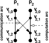
A communication graph of is a directed acyclic graph where the set of vertices corresponds to the communication events and the arc set consists of two disjoint arc sets: the computation arc set and the communication arc set . Each vertex represents an event in the system: vertex represents the start of process , vertex , , represents either a send or a receive event, and vertex represents the end of a process. An arc, , , represents a computation within process and an arc represents a communication between different processes, and , where is a send vertex, and is a receive vertex (e.g. Figure 2). Note, the process arcs are drawn without orientation for clarity; they are always oriented downwards. Communication graphs are comparable to the time-space diagrams—without internal events—noted in [18].
The th process component of is the subgraph where and . The process component corresponds to a process in . We construct communication graphs by connecting process components with arcs. Hence, it is more intuitive to treat a process component as a chain of send and receive vertices bound by a start and an end vertex. A channel is represented by a channel pair of process components.
A t-ring is a subgraph of a communication graph , consisting of process components, such that in each of the process components there is a send vertex and a receive vertex , , such that the arcs and , are in . This definition is equivalent to the definition of a crown in [4].
A t-ring represents a circular dependence of alternating send and receive events; see the example in Figure 3. The shaded arcs in Figure 3 show how each receive event depends on the preceding send event and each send event depends on the corresponding receive event. Thus, without an available buffer, there is a circular dependency that results in the system deadlocking.
To model the execution of a system , we define a colouring game that simulates the execution of the system with respect to .
3.2 Colouring the Communication Graph
Given a communication graph , an execution of a corresponding system is represented by a colouring game where the goal is to colour all vertices green; a green vertex corresponds to the completion of an event. We use three colours to denote the state of each event in the system: a red vertex indicates that the corresponding event has not yet started, a yellow vertex indicates that the corresponding event has started but not completed, and a green vertex indicates that the corresponding event has completed. Hence, a red vertex must first be coloured yellow before it can be coloured green; this corresponds to a traffic light changing from red, to yellow, to green.111Naturally, we refer to a European traffic light.
We use tokens to represent buffer allocations. A buffer assignment of a process (or channel) is represented by a pool of tokens associated with the corresponding process component (respectively, the channel component). A instance of buffer utilization is represented by removing a token from a token pool and placing it on the corresponding communication arc.
The colouring game represents an execution via the following rules. Initially, the start vertices of are coloured green and all remaining vertices are coloured red; this is called the initial colouring.
| sendyel | A red send vertex may be coloured yellow if the preceding vertex is green—the send is ready. | |
| recvyel | A red receive vertex may be coloured yellow if the corresponding send vertex is yellow, and the preceding vertex (in the same process component) is green—both the send and the receive are ready. | |
| recvyel | A red receive vertex may be coloured yellow if the corresponding send vertex is yellow, and a token from the corresponding token pool is placed on the incident communication arc—the send is ready and a buffer is used. | |
| sendgrn | A yellow send vertex may be coloured green if the corresponding receive vertex is coloured yellow—the communication has completed from the sender’s perspective. | |
| recvgrn | A yellow receive vertex may be coloured green if both of its preceding vertices are green. If the incident communication arc has a token, the token is returned to its token pool—a receive completes after the send completes. | |
| endyel | A red end vertex may be coloured yellow if the preceding vertex is green. | |
| endgrn | A yellow end vertex may be coloured green. |
Buffer utilization is represented by placing a token from the token pool on the selected arc, and colouring the corresponding receive vertex yellow. If no tokens are available, the rule cannot be invoked.
A colouring of , denoted by , is a colour assignment to all vertices, which can be obtained by repeatedly applying the colouring rules, starting from the initial colouring. A colouring sequence is a sequence of colourings such that each colouring is derived from the preceding one by a single application of one of the colouring rules. An execution of a multiprocess system with buffer assignment is represented by a colouring sequence on . Each transition, from one colouring to the next, within a colouring sequence, corresponds to a change of state of an event in the corresponding execution. Assuming that all events in the system are ordered, there is a correspondence between the colouring sequences on and the executions of system . Using the correspondence between colouring sequences on and executions of system , we reason about system by reasoning about colouring sequences on .
We say that a colouring sequence completes if and only if the last colouring in the sequence comprises only green vertices. A colouring sequence deadlocks if and only if the last colouring in the sequence has one or more non-green vertices and the sequence cannot be extended via the application of the colouring rules. A system is safe if and only if every colouring sequence on the graph completes.
We say that a colouring sequence blocks if there exists a sequence on , ending with a colouring containing a yellow send vertex, that cannot be extended by applying rule recvyel to the corresponding receive vertex. A colouring sequence is block free if every prefix of the sequence does not block; a communication graph , is block free if all colouring sequences on it are also block free. If is block free, then no send in will ever block during an execution.
A token assignment, also denoted by , is a list of nonnegative integers, denoting the number of tokens assigned to each token pool; the token assignment is the abstract representation of a buffer assignment. The number of tokens required depends on the number of times that rule recvyel can be invoked. If a token pool is empty, this means all buffers are in use.
4 Useful Lemmas
The following lemmas are used throughout our proofs. Lemma 4.1 characterizes the conditions under which a colouring sequence will deadlock. Lemma 4.2 characterizes conditions under which a single colouring sequence may represent all possible colouring sequences. Finally, Lemma 4.3 characterizes a class of communication graphs on which no colouring sequence will deadlock.
Lemma 4.1 (The t-Ring Lemma)
Let be a communication graph comprising a single t-ring. Any colouring sequence on completes if and only if rule recvyel is invoked at least once.
-
Proof: Assume by contradiction that there exists a complete colouring sequence that does not make use of rule recvyel. Consider the first colouring in where one of the send vertices is green; call the vertex . Let be the corresponding receive vertex. According to rule sendgrn, the vertex must be yellow. Since rule recvyel has not been applied, rule recvyel must have been invoked earlier in the sequence. By the definition of a t-ring, the send vertex must be the predecessor of . Since the rule recvyel was applied to , must be green. Hence, there is an earlier colouring in with a green send vertex. This is a contradiction.
In the other direction, if rule recvyel is invoked on receive vertex , then rule sendgrn can be invoked on the corresponding send vertex , breaking the circular dependency.
Define the dependency graph of communication graph to be where all process arcs in are reversed in and all communication arcs in are bidirectional in . Define the depth of a vertex to be the maximum length path in from to a start vertex.
Lemma 4.2
Let be communication graph with a token assignment of . For any vertex in , if there exists a colouring sequence that colours vertex green, there does not exist a colouring sequence that deadlocks before colouring green.
-
Proof: Proof by contradiction. Assume that there exist two colouring sequences, such that one colouring sequence colours a vertex green and the other deadlocks and does not colour the vertex green. Let be such a vertex of minimum depth; that is, all vertices of lesser depth will be coloured green eventually by any colouring sequence on . In order for a vertex to be coloured green, its component predecessor must be green. Since the depth of the predecessor is less than the depth of , it can always be coloured green. Furthermore, since a send and its corresponding receive vertex are adjacent to each other, their depths differ by at most .
Since must be a communication vertex, by rules sendgrn and recvgrn, the adjacent communication vertex must be coloured yellow before can be coloured green. If vertex is of a lesser depth than , then must be green colourable in all colouring sequences; hence, must also be green colourable. If is at the same depth as , then its component predecessor is at a lesser depth and must be green colourable, hence is yellow colourable, and is green colourable. If is at a greater depth than , the component predecessor of , say , is at the same or a lesser depth than . If the latter, then is green colourable and is yellow colourable, otherwise, we apply the same argument to first. Since there is no path from to in —because —we need only recurse a finite number of times.
Lemma 4.3
If is a communication graph whose dependency graph is acyclic, then no colouring sequence on will deadlock.
-
Proof: Proof by contradiction. Assume that a colouring sequence deadlocks on . Let be the vertex of minimum depth that cannot be coloured green. If is a send (receive) vertex, let be the corresponding receive (send) vertex. Let vertex be the component predecessor of vertex and let vertex be the component predecessor of vertex . Since the dependency graph is acyclic, the depths of both and are less than the depths of and . Hence, both and may be coloured green based on our minimality assumption. However, then both and may be coloured green; this is a contradiction! If is an end vertex, then it has only one predecessor, which is of a lesser depth, which leads to the same contradiction.
5 Buffer Allocation in Systems with Receive Side Buffers
In systems with receive side buffers, messages are buffered only by the receiver. Buffers are allocated by the receiving process when a message arrives, but cannot be received, and are freed when the message is received by the application. Analogously, when colouring a receive vertex of the corresponding communication graph, only a token belonging to the same process component may be used. We call this the receive side allocation scheme.
5.1 The Buffer Allocation Problem
In order to prevent deadlock in distributed applications, the underlying system needs to allocate a sufficient number of buffers. Ideally, it should be the minimum number required. Unfortunately, determining the required number of buffers, such that the system is safe, is intractable.
The corresponding graph-based decision problem is this: given a communication graph and a positive integer , determine if there is a token assignment of size such that no colouring sequence deadlocks on . We show that is -hard by a reduction of the well known 3SAT problem [5] to . Recall the definition of 3SAT: determine if there exists a satisfying assignment to , where , , and are Boolean literals in .
Theorem 5.1
The Buffer Allocation Problem () is -hard.
-
Proof: Proof by reduction of 3SAT to . For any 3SAT instance we construct a corresponding communication graph such that for a token assignment of size , any colouring sequence completes on if and only if the corresponding variable assignment satisfies .
Let be an instance of 3SAT with variables and clauses; the variables are denoted , and the th clause is denoted , where . The corresponding communication graph comprises process components: of the components—called literal components—are labeled and , , and correspond to the literals of . The last component—called the barrier component—is labeled .
Each process component is divided into epochs, where each epoch is a consecutive sequence of zero or more vertices within the component. All epochs are synchronized, that is, the vertices of one epoch must be coloured green before any of the vertices in the next epoch may be coloured. To ensure this we use a barrier component; the th epoch of the barrier component, , comprises receive vertices, labeled , and send vertices, labeled , . At the end of each epoch there is an arc from each of the literal components , , to the barrier component. Each arc emanates from vertex , called a barrier send vertex, and is incident on vertex , where and . These arcs are followed by arcs emanating from the barrier component to the literal components; the arcs emanate from vertices and are incident on vertices , called barrier receive vertices. The barrier widget has no cyclic dependencies. Hence, by Lemma 4.3, no colouring sequence will deadlock on a barrier widget.
Epoch fixes a token assignment corresponding to a variable assignment in 3SAT. Each pair of process components, and , , forms a variable widget, which corresponds to a variable. The two process components of a pair share a 2-ring; see Figure 4. By Lemma 4.1, at least one token must be assigned to either process component or to prevent all colouring sequences from deadlocking on . Since only tokens are available, each component pair can be assigned exactly one token. Finally, assigning the token to process component, or , corresponds to fixing variable to true or false. The epoch terminates with a barrier send vertex , followed by a barrier receive vertex , .
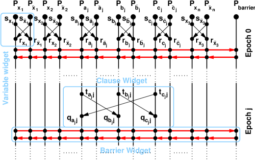
Figure 4: Construction of G.
Epoch of each process component corresponds to the th clause of . The epoch of a process component , —not labeled by a literal of the th clause—contains only two vertices: the barrier send vertex and the barrier receive vertex . The three process components, , , , whose labels correspond to the literals in the th clause share a 3-ring in the th epoch; see Figure 4. By Lemma 4.1, to avoid deadlock, at least one of the three process components must have a token. If none of the components are assigned a token, all literals in the th clause are false. The epoch is terminated by the barrier send and the barrier receive vertices.
A satisfying assignment on satisfies at least one literal in every clause. A corresponding token assignment assigns a token to the corresponding process component in each 3-ring—corresponding to the true literal. Hence, by Lemma 4.1 none of the colouring sequences will deadlock on any of the clause widgets and any colouring sequence on will complete.
For a falsifying assignment of , there exists at least one clause comprising false literals. The corresponding token assignment fails to assign any tokens to the process components that share the corresponding 3-ring. Thus, by Lemma 4.1 all colouring sequences will deadlock in that clause widget.
Hence, for a token assignment of size , any colouring sequence on will complete if and only if the corresponding assignment satisfies . Since finding a token assignment of size such that no colouring sequence on deadlocks is as hard as finding a satisfying assignment for , is -hard.
5.2 The Buffer Sufficiency Problem
A potentially simpler problem involved verifying whether a given buffer assignment is sufficient to prevent deadlock. Formally, given a graph and a token assignment on , determine if none of the colouring sequences on deadlock. This problem turns out to be intractable as well.
We show that is -complete by a reduction from the TAUTOLOGY problem [13, Page 261] to . Given an instance of a formula in disjunctive normal form (DNF), where , the formula is a tautology if it is satisfied by all assignments. An assignment that falsifies is a concise proof that the formula is not a tautology. We shall restrict our attention to 3DNF formulas, where each term has three literals: .
Theorem 5.2
The Buffer Sufficiency Problem () is -complete.
-
Proof: Let be a communication graph along with a token assignment. If there exists a deadlocking colouring sequence on , then the sequence itself is a certificate. The sequence is at most twice the number of vertices in . Hence, is in .
Let be a 3DNF formula with terms where each term has three literals. For any 3DNF formula , we construct a communication graph and fix a token assignment such that there is a colouring sequence on that deadlocks if and only if the corresponding assignment falsifies . The construction consists of four types of widgets that correspond to fixing an assignment, a term in the disjunction, the disjunction, and the interconnects between widgets.
Each variable in is represented by a variable widget comprising three process components that are labeled , , and . The latter, called the arbitrator component, comprises three receive vertices, labeled , , and . The former two process components, called variable components, comprise two send vertices each. The first, labeled (), is adjacent to the corresponding receive vertex ( in the arbitrator component. The second, labeled (), is adjacent to receive vertices in widgets called dispersers, described later. The vertex in the arbitrator component is similarly adjacent to a vertex in a disperser widget. The corresponding token assignment for each variable widget assigns one token to and no tokens to the other two components; see Figure 5. The widget has the following property:
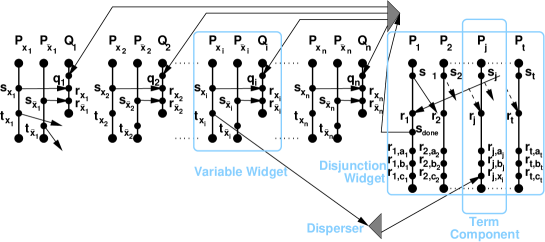
Figure 5: The construction.
Property 5.3
Let be a communication graph that contains a variable widget. Any colouring sequence on may colour exactly one of the two vertices or yellow before vertex is coloured green.
-
Proof: By rule sendyel, in order for () to be coloured yellow, vertex () must be coloured green. Hence, by rule sendgrn, vertex () must first be coloured yellow. Since vertex is red, vertex () can only be coloured yellow via rule recvyel. However, there is only one token assigned to process component , hence rule recvyel may only be invoked once.
The th term in the disjunction is represented by a term widget comprising a process component, which is called the term component and labeled . The first part of each term component consists of a send vertex and a receive vertex ; these vertices are part of a -ring. In the first term component, , there is an additional send vertex labeled ; these are described in the next paragraph. The second part of each term component consists of three receive vertices labeled , , and , where correspond to the literals in the th term; see Figure 5. These receive vertices are adjacent to send vertices in widgets called dispersers, which are described later. The term components are used to construct a disjunction widget.
The disjunction widget comprises term components, where the first two vertices, and , are part of a -ring spanning all components. Specifically, each send vertex , , is adjacent to receive vertex and vertex is adjacent to receive vertex ; see Figure 5. Each term component is assigned one token. The disjunction widget has the following property.
Property 5.4
Let be a communication graph that contains a disjunction widget. Any colouring sequence on can colour , , green if and only if at least one of , , is coloured yellow before any , , or are coloured yellow.
-
Proof: By Lemma 4.1, vertex can be coloured green, if and only if rule recvyel is invoked, colouring one of the receive vertices , , yellow. The rule may only be invoked if and only if a token is available. Since each term component only has one token assigned and since vertex precedes vertices , , and , a token is available if and only if none of the vertices , , and , are coloured yellow via rule recvyel, before vertex is coloured yellow.
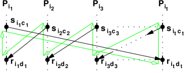
Once vertex , , is coloured yellow, all , may be coloured green, and vertex may be coloured yellow. We now describe how the widgets are connected together using disperse widgets. Let be a send vertex and be a set of receive vertices. An -disperser comprises process components: one master component, labeled , and slave components labeled , . The master component comprises one receive vertex labeled , followed by send vertices labeled , . Each send vertex is adjacent to the receive vertex on the corresponding slave component . Each slave component has two vertices: a receive vertex , followed by a send vertex ; see Figure 6. The latter vertex is adjacent to the receive vertex in some other widget. None of the components are assigned any tokens. The following property of a disperser follows from Lemma 4.3.

Property 5.5
Let be a communication graph containing an -disperser. If a colouring sequence colours vertex yellow, then the colouring sequence can be extended to colour all vertices , yellow.
Let , , be the set of receive vertices labeled , , and let be similarly defined; recall that are simply literal place holders in the vertex labels , , . Hence, a -disperser connects send vertex to vertices in —belonging to the term components. Furthermore, let be the set of receive vertices (in the variable widgets), ; a -disperser connects vertex to all variable widgets via receive vertices . The construction of comprises variable widgets and one disjunction widget, composed of term widgets; these are connected together by a -disperser, and -dispersers, where . We claim that there exists a colouring sequence that deadlocks on if and only if there is a falsifying assignment for formula , that is, is not a tautology.
Suppose that has a falsifying assignment , that is every term in the disjunction is false because each term has a literal or , which is false. To construct a colouring sequence on that deadlocks, we construct a set of vertices . The first half of the colouring sequence is a maximal colouring sequence involving only the vertices of . The second half of the sequence may involve all vertices in . The resulting colouring sequence will always deadlock.
Let , which is the set of literals that are false, and let , which contains the set of send vertices from the variable components that are labeled by a true literal and the numbered send vertices in the disjunction widget; the set contains the vertices which may not initially be coloured. Let be the rest of the vertex set.
Consider a colouring sequence involving only vertices in . By property 5.3 any maximal colouring sequence will colour the vertices yellow (in the variable widget), where . Hence, by property 5.5 the vertices (in the dispersers) will be coloured yellow, where —the send vertices in the dispersers are adjacent to the receive vertices in . Since is a falsifying assignment, every term contains a literal, which is falsified by . Without loss of generality, let denote a literal that is false in the th term; therefore, process component contains a receive vertex , which is adjacent to the yellow send vertex (in the disperser). Since none of the vertices of the -ring (in the disjunction widget) are not in —they are still coloured red—the token belonging to component is used to apply rule recvyel to colour vertex yellow. Since every term has a false literal, the colouring sequence colours a receive vertex , in every term component . After the sequence cannot be extended, allow all vertices to be coloured; since vertices (in the term components), , have been coloured yellow before vertex (in term component ), according to property 5.4, the sequence will deadlock.
If a colouring sequence on deadlocks, according to property 5.4, deadlock occurs only if there is a yellow vertex labeled , , or in each of the term components. Their predecessors—vertices , , in the dispersers—must be green. Since the colouring sequence is maximal, by property 5.3 exactly one of or is red, thus this corresponds to a valid assignment: setting if is green, or if is green yields an assignment that falsifies .
Thus, a colouring sequence on deadlocks if and only if the corresponding assignment falsifies . Hence, is -complete.
Therefore, just determining whether a buffer assignment is sufficient is intractable, even one as simple as in the preceding example. Intuitively, the buffers of a process are assigned based on the behaviour of other processes; thus, buffer utilization is not locally decidable. Further, the order in which buffers are assigned is nondeterministic, exploding the search space of possible buffer utilizations. This phenomena, which our proofs rely on, is what we call buffer stealing. For example, in a system corresponding to the variable widget (see Figure 5), the first process to send its message gets the buffer, and the other process remains blocked until the arbitrator performs the receives. This stealing corresponds to fixing a value of a variable. Similarly, the system corresponding to the disjunction widget allocates buffers for each of the term processes. However, if the buffer is stolen in all terms, corresponding to a falsifying assignment, then the system will deadlock within the ring.
For completeness, we note the following corollary:
Corollary 5.6
The Buffer Allocation Problem () is in .
-
Proof: By Theorem 5.2, verifying that a token assignment is sufficient to prevent deadlock () is -complete. Since we can nondeterministically guess a sufficient token assignment, the result follows.
5.3 The Nonblocking Buffer Allocation Problem
In addition to the system being safe, we can require that no sending process ever blocks due to insufficient buffers on the receiving process. The Nonblocking Buffer Allocation Problem () is to determine the minimum number of buffers needed to achieve nonblocking sends.
Formally, the corresponding decision problem is this: given a communication graph and an integer , determine if there exists a token assignment of size such that no colouring sequence on blocks. Recall that a colouring sequence does not block if, whenever a send vertex is coloured yellow, rule recvyel may be applied to the corresponding receive vertex.
Let and , , be two process components. Given two vertices, and , in , , vertex is communication dependent on vertex if is the start vertex or if there exists a vertex , such that there is a path from to and the arc is in (see Figure 7). Vertex is terminally communication dependent on vertex if is communication dependent on and is not communication dependent on the vertices , . The algorithm depicted in Figure 8 computes an optimal token assignment such that no colouring sequence on can block.

1. For each receive vertex determine its terminal communication dependency, vertex , where . 2. Set to be the interval between vertex and vertex . 3. For each process component , compute , the maximum overlap over all intervals . 4. is the optimal nonblocking token assignment.
Remark 5.7
In a system corresponding to communication graph , the time between a message arriving at process and its receipt corresponds to the interval . Each interval must have a buffer to ensure nonblocking sends. Hence, the minimum number of buffers, , is the maximum overlap over all intervals within process .
Computing the terminal communication dependencies for can be done via dynamic programming in time, where is the vertex set of and is the number of process components. If there exists a path from vertex to , then there exists a path from to all vertices , . Associate with each vertex an integer vector of size ; means that there exists a path from to , and thus to , . The vector is computed by taking the elementwise minimums over the vectors of the adjacent vertices ; this is simply a depth-first traversal of . Since the number of arcs is bounded by and the pairwise comparison takes steps, the traversal takes time.
Next, computing the intervals, , requires one table lookup per interval. To compute the maximum overlap we sort the intervals and perform a sweep, keeping track of the current and maximum overlap; this takes time. Thus, the total complexity is time. In the worst case, where , this algorithm is quadratic. However, in practice is usually fixed, in which case the term dominates.
5.3.1 Proof of Correctness of the Nonblocking Buffer Allocation Algorithm
Lemma 5.8
Let be a communication graph. For all vertices ; if is a send vertex and there exists a path from the vertex to vertex , then vertex cannot be coloured yellow until vertex is coloured green.
-
Proof: By rule sendyel, the predecessor of must first be coloured green before can be coloured yellow. Since rules sendgrn, and recvgrnimply that the predecessors of a green vertex must be green, the result follows.
Corollary 5.9
Let , , and be as in Lemma 5.8 and let be the receive vertex corresponding to the send vertex . Rule recvyel will never be applied to vertex before vertex is coloured green.
The preceding corollary implies that a token, which is needed to colour the receive vertex yellow, need not be available until the vertex on which is terminally communication dependent is coloured green. Hence, it is sufficient to ensure token availability just before colouring the respective send vertex green; this is also necessary.
Theorem 5.10
Given , let be a send vertex and be a receive vertex that is terminally communication dependent on vertex . A token for the application of rule recvyel on arc must be available as soon as vertex is coloured green.
-
Proof: Let be the send vertex corresponding to the receive vertex and let be the set of vertices that are predecessors of , but on which is not communication dependent.
Since is not communication dependent on the vertices in , we can construct a colouring sequence on that fixes the vertices in to be red, and colours vertex yellow, making the application of rule recvyel possible in the next step. Since no progress is made in the th process component after colouring vertex green, the state of the associated token pool does not change until the application of rule recvyel to vertex . Hence, when vertex is coloured green, the token pool must have a token destined for arc .
Thus, if a receive vertex is terminally communication dependent on a send vertex , then it is necessary and sufficient that a token, which is used to apply rule recvyel to receive vertex , must be available as soon as the send vertex is coloured green; the start vertex may be thought of as a special send vertex. Since the interval corresponding to begins when is coloured green, and ends when is coloured green, a token must be available for the recvyel rule, which can occur during this interval. Computing the maximum overlap of intervals yields the required number of tokens.
5.3.2 Example Use of the Algorithm
To demonstrate the algorithm we have implemented it, and analyzed the pipe-and-roll parallel matrix multiplication algorithm [10]. The program has one control process and a number of worker processes arranged in a 2 dimensional mesh. We ran the algorithm on meshes of size , and . The communication graph for the smallest example, comprising four workers ordered in a mesh, is depicted in Figure 9. The corresponding optimal buffer assignment is listed in the second column of Table 1.

In this example, process 0 is the control process and processes 1 through 4 are the workers. The control process needs 4 buffers and the workers each need 3 to execute without blocking. The results obtained when executing the algorithm on a worker system is 9 buffers for the control process and between 4 and 5 buffers for the worker processes. For the system the numbers are 16 for the control process and between 5 and 7 buffers for the workers.
| Proc. | Max overlap | Overlap for intervals Ij | ||||||||
|---|---|---|---|---|---|---|---|---|---|---|
| I1 | I2 | I3 | I4 | I5 | I6 | I7 | I8 | I9 | ||
| 0 | 4 | 0 | 0 | 0 | 0 | 4 | 3 | 2 | 1 | 0 |
| 1 | 3 | 2 | 1 | 2 | 3 | 2 | 1 | 1 | 0 | 0 |
| 2 | 3 | 3 | 2 | 1 | 2 | 1 | 1 | 1 | 0 | 0 |
| 3 | 3 | 3 | 2 | 1 | 2 | 1 | 1 | 1 | 0 | 0 |
| 4 | 3 | 2 | 1 | 2 | 3 | 2 | 1 | 1 | 0 | 0 |
Table 1. The result of running the algorithm on the worker example.
5.3.3 Approximating with
The algorithm is useful for determining a token assignment that prevents deadlock, that is, approximating . Since a nonblocking colouring sequence does not deadlock, a token assignment determined by the algorithm ensures that the graph is deadlock free. However, the token assignment may be far from optimal. A simple example of this phenomena is a two process component graph comprised of arcs emanating from the first component and incident on the second. Such a graph requires zero tokens to avoid deadlock, but requires tokens to be block free. Thus, the aforementioned token assignment may entail many more tokens than required.
6 Buffer Allocation in Systems with Send Side Buffers
In this section we consider the second of the four buffer placement strategies: send side buffers. Buffers are now allocated on the sending process side if the receive is not ready to accept the message. Correspondingly, the token pool used when applying rule recvyel to the receive vertex of arc belongs to the process component containing the send vertex . We call this the send side allocation scheme.
The Buffer Allocation Problem () remains intractable. The problem is conjectured to be -complete (see the following paragraph). The -hardness follows from the observation that each t-ring in the construction in Theorem 5.1 has to have a token assigned to a process component pair in order to prevent deadlock. It does not matter if the token is allocated from the token pool of the sending or the receiving process component. Hence, the reduction used in Theorem 5.1 can be applied with no modification.
We conjecture that the corresponding Buffer Sufficiency Problem () is in . This is because the relative order in which tokens from a particular token pool are utilized is invariant with respect to the colouring sequences. Hence, we believe that the determining sufficiency is similar to the nonblocking buffer allocation problem and hence is in . If this is the case, is -complete.
The Nonblocking Buffer Allocation Problem () remains in . The problem can be solved by first reversing all arcs in the communication graph, swapping the start and end vertices, and then running the algorithm described in Figure 8.
7 Buffer Allocation in Systems with Send and Receive Side Buffers
So far we have considered systems exclusively with send side or receive side buffers. In this section we investigate systems with buffers on both the send and the receive sides; many communication systems use per-host buffer pools for both receiving and sending messages. The choice of where to buffer the message—on the sender or on the receiver—increases the difficulty of determining the system’s properties.
We assume a lazy mechanism for utilizing buffers: first use a buffer from the sender’s pool. If none is available, use a buffer from the receiver’s pool. If neither is available, attempt to free a send side buffer by transferring its contents to a buffer belonging to the corresponding receiver. Intuitively, the system attempts to maximize buffer use, without attempting to predict the future.
The corresponding colouring game allows tokens to be allocated from the pools belonging to both the sending component and the receiving component. Correspondingly, a lazy token utilization scheme is used: let be a communication arc from process component to process component . The following rules apply during the application of rule recvyel to vertex :
-
1.
If a token belonging to component is available, use it.
-
2.
Otherwise, if a token belonging to component is available, use it.
-
3.
Otherwise, if a token belonging to component is currently placed on arc , , , and a token belonging to component is available. Then the token on arc may be replaced with the one belonging to , freeing a token to be used in the current application of rule recvyel.
We call this the mixed allocation scheme.
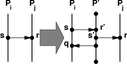
Not unexpectedly, the Buffer Allocation Problem () remains intractable within the mixed allocation scheme. This is because the receive side allocation scheme, which provides no choice of token pools, can be simulated within the mixed allocation scheme. Concretely consider the receive side allocation scheme analyzed in Section 5: to simulate the receive side allocation scheme on communication graph , within the mixed allocation scheme, each arc in is replaced by the widget illustrated in Figure 10. Since vertex cannot be coloured green until vertex is coloured yellow, and component has no tokens, applying rule recvyel to requires that has an available token, regardless of whether has an available token.
Similarly, the Buffer Sufficiency Problem () within the mixed allocation scheme is also -complete. The hardness follows from Theorem 5.2 and the preceding argument. Since a colouring sequence also serves as a deadlock certificate in this case, the -completeness result follows.
The interesting property of the mixed allocation scheme is that the Nonblocking Buffer Allocation Problem () is intractable; the choice of token pools increases the search space of solutions exponentially! The reduction is from 3SAT.
Theorem 7.1
The Nonblocking Buffer Allocation Problem () is -hard.
-
Proof: Let be an instance of 3SAT, comprising variables, labeled , , and clauses. We construct a communication graph such that there exists a token assignment of tokens that prevents any colouring sequence from blocking on if and only if the corresponding assignment satisfies .
The graph comprises process components: the first are labeled and , , and the remaining three process components are labeled , and , respectively. The graph is divided into epochs: epoch corresponds to the variable assignment, and epochs through correspond to clause evaluation.
In epoch each process component contains a single send vertex that is adjacent to the receive vertex located in epoch of process component . Process component (and ) contains four vertices: two receive vertices and (respectively and ), followed by two send vertices and (respectively and ). Finally, process component contains eight vertices: two send vertices, and , that are adjacent to vertices and ; two receive vertices, and , that are adjacent to and ; two more send vertices, and , that are adjacent to and ; and two more receive vertices, and , that are adjacent to and . See Figure 11. Epoch has two important properties.
Property 7.2
Any token assignment must assign at least one token to either component or to prevent the colouring sequence from blocking after colouring vertex yellow.
Property 7.3
A token assignment on having only tokens must assign two tokens to process component to prevent a colouring sequence from blocking after yellow colouring one of the send vertices , , or .
-
Proof: Since tokens must be allocated to the process components or , , this leaves only two tokens to be allocated. Since the colouring rule sequence sendyel, recvyel, sendgrn, sendyel, recvyelcan colour send vertices and , or send vertices and , component pairs and must each have two tokens between them. This can only happen by assigning the tokens to .
A corollary of these properties is that once a legal token assignment is made, no colouring sequence will block in epoch 0. The choice of allocating the token on versus corresponds to fixing the variable assignment.

For , epoch corresponds to the th clause. Each epoch comprises two parts of six arcs each: the synchronization part and the evaluation part. Four process components are involved in an epoch: the three components, , , and , whose labels are the literals in the th clause, where , and component , which is involved in every epoch. Epoch of component comprises four vertices: receive vertex , send vertex , receive vertex , and send vertex . Process components and are analogously formed.
In epoch component has 12 vertices, the first six are these: send vertex , receive vertex , send vertex , receive vertex , send vertex , and receive vertex . These are followed by three send vertices: , , and , and three receive vertices: , , and .
Each vertex is adjacent to vertex , each vertex is adjacent to vertex , each vertex is adjacent to vertex , and each vertex is adjacent to vertex ; see Figure 11. For conciseness we drop the last index, , if it is obvious from the context. Epoch has three important properties:
Property 7.4
If vertex (in epoch ) is coloured green and vertex (in epoch ) is still red, then no tokens that belong to component are assigned to arcs. The same applies to vertex pairs , , and , also in epoch .
-
Proof: All ancestors of must be coloured green and all descendants of must be coloured red. This includes all vertices in , except some vertices and in epoch , which are not adjacent to vertices in component . Hence, the tokens belonging to are not assigned to any arc. The same argument applies to the other vertex pairs.
Property 7.5
A colouring sequence on can block only when yellow colouring receive vertices , , , , , or .
-
Proof: As a corollary of properties 7.2 and 7.3, no colouring sequence can block in epoch . Thus, we need only check that no colouring sequence can block in the first part of epoch , .
By property 7.4, if is red and its predecessor is green, then no tokens of are in use. Hence, to colour green, a token is available to colour yellow. Since vertex is a predecessor of , vertex must be coloured green before may be coloured yellow. Thus the token is freed before is coloured green, and may be used to colour vertex yellow after is coloured yellow. A similar argument applies to the vertices , , , and .
Property 7.6
A colouring sequence can block in epoch if and only if none of the three process components, , , and , have a token assigned.
-
Proof: For the ‘if’ direction consider a colouring sequence that colours vertex green, but has not yet coloured vertex yellow. By definition, blocking does not occur, if rule recvyel may always be applied to colour a receive vertex yellow. To colour the send vertices , , and yellow and then green, the receive vertices , , and , must be coloured yellow via rule recvyel. Since the receive vertices , , and are not ancestors of the send vertices , , and , none of the receive vertices need be coloured green before the send vertices are coloured yellow. However, component has only two tokens, and none of components , , have any. Hence, rule recvyel can only be invoked twice, instead of the requisite three times. Thus, a colouring sequence can block in epoch .
For the ‘only if’ direction we claim that if a literal component , , or has a token, rule recvyel can be invoked on any of the six receive vertices , , , , , and . Since is a predecessor of , must be coloured green before , and hence before is coloured yellow. Thus, the same token that was allocated upon the application of rule recvyel to vertex , may also be allocated upon the application of rule recvyel to vertex ; the same argument is applicable to vertices and . Applying rule recvyel to vertices and , uses the two tokens from component . To colour vertex yellow there are three possible scenarios:
-
1.
the colouring sequence has already freed one of the tokens, allowing it to be reused,
-
2.
component has a token, in which case it is used, or
-
3.
component (or ) has a token, in which case it replaces the token used to yellow colour vertex (or ) and the freed token is used to colour vertex .
Since at least one component , , or have a token, the claim is proven.
-
1.
By property 7.6 a colour sequence will block in epoch if and only if none of the process components , , or has a token, which corresponds to the th clause having no literals that are true. Thus, a token assignment of size prevents any colouring sequence on from blocking if and only if the corresponding assignment satisfies .
8 Buffer Allocation in Channel Based Systems
In channel based systems processes communicate via pairwise connections that are created at start-up. Each connection, called a channel, is specified by its end-points and is used by one process to send messages to the other. Each channel functions independently of other channels in the system, and resources such as buffers are allocated on a per channel basis, rather than per process. Finally, channels behave like queues, that is, messages are removed from the channel in the same order that they are inserted.
Channels may either be unidirectional, comprising source and destination end-points, or bidirectional, comprising two symmetric end-points. In the former case, only the source process may insert messages into the channel and only the destination process may remove messages from the channels. A bidirectional channel is equivalent to two unidirectional channels, allowing both processes to insert and remove messages from the channel. Here we only consider unidirectional channels.
Except for buffer allocation, channel based communication does not differ from the previously described send/receive mechanism. In fact, an unbuffered channel communication is just a synchronous send/receive communication. Thus, we can derive similar results for channel based systems.
In the corresponding colouring game tokens, are allocated to channels (component pairs) instead of to components. This change does not change the properties used in our proofs. In fact, Lemma 4.1 may be used unchanged. We call this the per channel allocation scheme.
8.1 The Buffer Allocation Problem
The corresponding Buffer Allocation Problem () is this: given a communication graph and an integer , determine whether there exist a token assignment of size , such that no colouring sequence deadlocks on . Even though token utilization, during the colouring of a communication graph, is only dictated by the communication arcs within a process component pair, determining the number of tokens needed remains -hard. The proof is similar in spirit to Theorem 5.1.
Theorem 8.1
The Buffer Allocation Problem () is -hard.
-
Proof: We prove this by reducing 3SAT to . For any 3SAT instance we construct a corresponding communication graph —polynomial in size of —such that for a token assignment of size , any colouring sequence will complete on if and only if the corresponding variable assignment satisfies .
Let be an instance of 3SAT on variables and comprising clauses. The construction is nearly identical to that in Theorem 5.1, except for the widgets representing the clauses of . The graph has process components that are labeled by the literals of , and , . Each component comprises epochs, where each epoch contains zero or two vertices.
As in Theorem 5.1, epoch fixes a variable assignment. In epoch each component has two vertices: a send vertex, labeled (or ), and a receive vertex , (respectively ), . Vertex is adjacent to vertex , and vertex is adjacent to vertex ; this is a 2-ring, identical to epoch in Theorem 5.1. Epoch has the the following property:
Property 8.2
Any colouring sequence on will deadlock in epoch unless each process component pair has a token assigned to the token pool of either , or , . Thus, the token assignment must be of at least size . (Follows from Lemma 4.1.)
Property 8.2 yields the following correspondence between assignments on and token assignments of size .
Property 8.3
The corresponding token assignment of a variable assignment on assigns a token to the channel if is true, or to if is false.
The th epoch represents the th clause of , denoted , where . The process components , , , , , and form a 6-ring, while the remaining components have no vertices in the th epoch. Process component has two vertices in the th component: a send vertex, , and a receive vertex ; similarly, the other five components have a send and receive vertex that are correspondingly named. The arcs linking the 6 components are these: , , , , , and . These form a 6-ring, as illustrated in Figure 12. The key property of the th epoch is this:

Property 8.4
No colouring sequence on will deadlock in the th epoch if and only if at least one of the channels has a token: , , , , , . (Follows from Lemma 4.1.)
A refined version of property 8.4 is more useful:
Property 8.5
For any token assignment of size such that no colouring sequence deadlocks on in epoch , no colouring sequence on will deadlock in the th epoch if and only if at least one of the channels , , and , has a token.
We claim that given a token assignment of size , any colouring sequence will complete on if and only if the corresponding variable assignment satisfies .
If an assignment satisfies , then every clause has at least one literal that evaluates to true. By Property 8.3, in each of the epochs at least one of the channels listed in Property 8.5 will be allocated a token. Hence, by Property 8.5 no colouring sequence will deadlock on .
If an assignment does not satisfy then there is at least one clause in which all literals are false. Let be the unsatisfied clause. By property 8.3, the corresponding token assignment will not assign a token to , , or , hence, by Property 8.5, all colouring sequences will deadlock.
Thus, is -hard.
Since tokens are assigned on a per channel basis, token usage depends only on the two process components that comprise the channel. Consequently, the sufficiency of a token assignment can be verified in linear time. Thus, the easier problem is in , implying that is -complete. We describe the verification algorithm and prove its correctness.
To verify the sufficiency of a token assignment, perform a colouring on : at each step of the colouring a vertex of is coloured according to the rules in section 3. Using a queue to keep track of colourable vertices, means that determining which vertex to colour next takes time. Since each vertex changes colour at most twice—the maximum length of any colouring sequence is colourings—colouring a graph takes time. The token assignment is sufficient if and only if the colouring sequence completes. The algorithm’s correctness follows immediately from the following theorem: any colouring sequence on completes if and only if some colouring sequence on completes. Thus, a token assignment is sufficient if and only if some colouring sequence on completes.
Theorem 8.6
Let be a communication graph and a token assignment on . Any colouring sequence on completes if and only if a colouring sequence on completes.
-
Proof: For any communication graph , we construct a new graph where every token is simulated by a process component, the size of the corresponding token assignment is zero, and every colour sequence on corresponds to a colouring sequence on , such that a colouring sequence on completes if and only if the corresponding colouring sequence on completes. Since the token assignment on is zero, by Lemma 4.2 a colouring sequence on completes if and only if every colouring sequence on completes. Hence, every colouring sequence on completes if and only if a colouring sequence on completes.
To simulate an token channel (a channel that has been assigned tokens) process components are chained together. For each channel with tokens, process components are interspersed between and . The channel is replaced with these channels: . Each arc from to is replaced by a chain of arcs from . The replacement is illustrated in Figure 13.
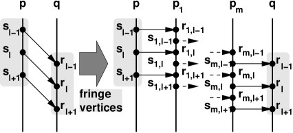
Figure 13: Simulating tokens by components.
We claim that a colouring sequence, , on will deadlock if and only if the corresponding colouring sequence, , on deadlocks. First, we construct the correspondence and argue its correctness. Second, we argue that sequence deadlocks on if and only if the corresponding sequence deadlocks on . Finally, we apply Lemma 4.2 to prove our result.
Since the transformation is iterative—each token channel is independent of the other channels—it is sufficient to derive the correspondence between the colouring sequence on and the graph where a single token channel has been replaced. Let denote the channel in that is replaced in .
Let , , denote the arcs from process component to . The corresponding paths in are
where each arc is within process component and each arc is between process components and ; the vertices and , are called the fringe vertices.
A colouring sequence can be represented as a sequence of differences (or moves), , between every two consecutive colourings and . The sequence is a sequence of colouring game moves such that applying to colouring yields , the next colouring in ; can be derived from and, can be derived from and . The sequence comprises two types of moves: those that colour fringe vertices, called fringe moves, and those that do not, called normal moves.
Given a colouring sequence on , we transform it into the corresponding colouring sequence on . The transformation replaces some fringe moves in sequence with sequences of moves, resulting in the corresponding move sequence . This sequence comprises normal moves and added moves; added moves are a mixture of fringe moves and moves on the vertices within the added components . There are four types of fringe moves in : colour a send vertex yellow (), colour a send vertex green (), colour a receive vertex yellow (), and colour a receive vertex green (). The transformation is performed in the order that the moves occur in sequence .
-
–
If , then no action is taken.
-
–
If , we replace it with the sequence
suffixed by the sequences
where is the smallest integer such that the move has not yet been inserted into the move sequence , that is, vertex has not yet been coloured green.
-
–
If , we remove it from the sequence; it is restored when we replace the move .
-
–
If we replace this move with the sequence
suffixed with the sequences
where , , and is the smallest integer such that the move has not yet been inserted into the sequence, that is, vertex has not yet been coloured yellow. Since the head of this sequence colours green, could be coloured yellow, if is yellow, then could be coloured green followed by and finally could be coloured yellow; this colouring cascades down the added process components.
It is important to note that each of the replacement sequences is maximal, that is, no additional valid colouring moves on the chain process components , , may be suffixed to them. The new sequence looks like this:
Since is a contraction of , all normal vertices are coloured by in the same order as in . Recall that normal vertices are not adjacent to the process component chain, and hence, are not affected by the transformation. While normal vertices within process components and may depend on the order that the fringe vertices are coloured, the dependence is via process arcs, not communication arcs. Consequently, the normal vertices only depend on the order that the fringe vertices are coloured green. Fortunately, this order is preserved. By inspection, the replacement sequences of moves are valid. Thus, the transformed sequence is valid. Additionally, all green colouring moves on fringe vertices are preserved by the transformation; a vertex is coloured green by if and only if the corresponding vertex is coloured green by . The following property is key:
Property 8.7
deadlocks on if and only if deadlocks on .
-
Proof: By contradiction, suppose that deadlocks on while can be extended, that is, another vertex colouring move may be suffixed to . Let be the vertex that can be coloured by the extension. Vertex may either be a normal vertex, a fringe vertex, or a vertex belonging to a process chain. The latter is impossible because every replacement sequence of moves is maximal.
If is a normal vertex, then its predecessors are either a normal vertex or a fringe vertex that has been coloured green. Since the transformation preserves the colourings of normal vertices and the order in which vertices are coloured green, if can be extended by colouring , then so can , which is a contradiction.
If is a fringe vertex, there are four cases: either is a send vertex being coloured yellow or green, or is a receive vertex being coloured yellow or green. The transformation does not affect moves that colour send vertices yellow and such a colouring only depends on its process component predecessor being green. Hence, if the colouring can be suffixed to , it can also be suffixed to ; resulting in a contradiction. If the extension colours the send vertex green, this means that the original sequence can be extended by either adding the colourings or , depending on whether has been coloured yellow or not in the original sequence ; thus, it is a contradiction.
Similarly, if is a fringe receive vertex being coloured green, this is not possible, because the transformation colours fringe receive vertices yellow, then green, by a single replacement sequence. Finally, if is a fringe receive vertex that can be coloured yellow, the original sequence can be extended by the move , because in the original sequence the corresponding send vertex has already been coloured green. Thus, we have another contradiction.
In the other direction, if the original sequence can be extended, then transforming the extension of the sequence yields an extension to the presumably deadlocked sequence . Thus, deadlocks on if and only if deadlocks on .
A corollary of Property 8.7 is that the colouring sequence deadlocks if and only if the colouring sequence deadlocks.
By Lemma 4.2 a colouring sequence on completes if and only if all colouring sequences on complete. Hence, a colouring sequence on completes if and only if all colouring sequences on complete.
Corollary 8.8
A colouring sequence on completes if and only if the token assignment is sufficient.
8.2 The Buffer Allocation Problem
For the Nonblocking Buffer Allocation Problem, the algorithm derived in section 5.3 suffices with a small modification. Since the token pools are per channel, rather than per process component, the computation must be performed on a per pool basis. Hence, there is an additional factor of in the runtime. Since each process may be using up to channels, the runtime of the algorithm becomes ; the cost increases because the number of allocations to be made becomes quadratic in .
9 Conclusion
As message passing becomes increasingly popular, the problem of determining -safety plays an increasingly important role. The relevance of this problem is grows as more and more functionality of message passing systems is off-loaded to the network interface card, where limited buffer space is a serious issue. Even if message passing is kept in main memory, buffer space can still be limited due to the sometimes very large data sets used in many parallel and distributed programs. Unfortunately, determining -safety is intractable.
We have shown that in the receive buffer model, determining the number of buffers needed to assure safe execution of a program is -hard, and that even verifying whether a number of assigned buffers is sufficient is -complete. On the positive side, if we require that no send blocks, we provide a polynomial time algorithm for computing the minimum number of buffers. By allocating this number of buffers, safe execution is guaranteed. In addition, we have implemented the algorithm, and it is now part of the Millipede debugging system [19].
For systems with only send buffers, the Buffer Allocation Problem remains -complete. In addition, we conjecture that the Buffer Sufficiency Problem can be solved in polynomial time because the order of the sends in each process is fixed. The Nonblocking Buffer Allocation problem for systems with only send buffers can be solved in polynomial time.
For systems with both send and receive buffers, the Buffer Allocation Problem as well as the Buffer Sufficiency Problem remain intractable. More interestingly, the Nonblocking Buffer Allocation problem has become intractable.
For systems with unidirectional channel buffers, both the Buffer Sufficiency Problem as well as the Nonblocking Buffer Allocation Problem have polynomial time algorithms. However, the Buffer Allocation Problem still remains an -complete problem. The results (conjectures) are summarized below.
| Buffer Placement | ||||
| Problem | Receive | Send | Send & Receive | Channel |
| BAP | -hard | -hard | -hard | -complete |
| BSP | -complete | () | -complete | |
| NBAP | -hard | |||
9.1 Strategies for Reducing Buffer Requirements
There are several strategies that a programmer can use to reduce the likelihood of deadlock when only a few buffers are available.
The obvious solution is to use synchronous communication, which does not require any buffers at all. However, this is not always desirable.
For efficiency reasons asynchronously buffered communication is often preferred. To decrease the risk of deadlock the programmer can introduce epochs that are separated by barrier synchronizations. This might reduce the number of buffers needed for each epoch, as no buffer requirement spans an epoch boundary. If each epoch only needs a small number of buffers, the risk of deadlock due to buffer insufficiency is reduced.
References
- [1] V. Anantharm. The optimal buffer allocation problem. IEEE Transactions on Information Theory, 35(4):721–725, 1989.
- [2] J. Bruck, D. Dolev, C. Ho, M. Rosu, and R. Strong. Efficient Message Passing Interface (MPI) for Parallel Computing on Clusters of Workstations. In 7th Annual ACM Symposium on Parallel Algorithms and Architectures, pages 64 – 73, Santa Barbara, California, July 1995.
- [3] G. Burns and R. Daoud. Robust MPI Message Delivery with Guaranteed Resources. MPI Developers Conference at the University of Notre Dame, June 1995.
- [4] B. Charron-Bost, F. Mattern, and G. Tel. Synchronous, asynchronous, and causally ordered communication. Journal of Distributed Computing, 9(4):173–191, 1996.
- [5] S. A. Cook. The complexity of theorem-proving procedures. In Proceedings of the 3rd Annual ACM Symposium on the Theory of Computing, pages 151–158, 1971.
- [6] R. Cypher and E. Leu. Repeatable and portable message-passing programs. In Proc. of The Symposium on the Principles of Distributed Computing (PODC), pages 22–31, 1994.
- [7] R. Cypher and E. Leu. The semantics of blocking and nonblocking send and receive primitives. In Proceedings of 8th IEEE International parallel processing symposium (IPPS), pages 729–735, 1994.
- [8] J. Dongarra. MPI: A message passing interface standard. The International Journal of Supercomputers and High Performance Computing, 8:165–184, 1994.
- [9] J. Dongarra, R. Hempel, A. Hey, and D. Walker. A proposal for a user-level, message-passing interface in a distributed memory environment. Technical Report TM-12231, ORNL, June 1993.
- [10] G. Fox, M. Johnson, G. Lyzenga, S. Otto J. Salmon, and D. Walker. Solving problems on concurrent processors. General techniques and regular problems, volume 1. Prentice-Hall, Inc., 1988.
- [11] D. Frye, R. Bryant, H. Ho, R. Lawrence, and M. Snir. An external user interface for scalable parallel systems. Technical report, IBM highly parallel supercomputing systems laboratory, November 1992.
- [12] G. Burns, R. Daoud and J. Vaigl. LAM: An Open Cluster Environment for MPI. In Supercomputing Symposium ’94, Toronto, Canada, June 1994.
- [13] M. R. Garey and D. S. Johnson. Computers and Intractibility: A Guide to the Theory of NP-Completeness. W. H. Freeman and Company, New York, 1979.
- [14] A. Geist, A. Beguelin, J. Dongarra, W. Jiang, R. Manchek, and V. Sunderam. PVM: Parallel Virtual Machine: A Users’ Guide and Tutorial for Networked Parallel Computing. Scientific and engineering computation. MIT Press, 1994.
- [15] P. Huber, A. M. Jensen, L. O. Jepsen, and K. Jensen. Reachability trees for high-level Petri nets. Theoretical Computer Science, 45:261–292, 1985.
- [16] K. Jensen. Coloured Petri nets. Basic Concepts, Analysis Methods and Practical use, volume 1. Springer Verlag, 1992.
- [17] C. Keppitiyagama and A. Wagner. Asynchronous MPI messaging on myrinet. In Proceedings 15th International Parallel and Distributed Processing Symposium (IPDPS’01). IEEE, 2001.
- [18] L. Lamport. Time, clocks and the orderings of events in a distributed system. Communications of the ACM, 21:558–565, 1978.
- [19] J. B. Pedersen. Multi-level Debugging of Parallel Message Passing Programs. PhD thesis, University of British Columbia, Canada, 2003. In preparation.
- [20] M. Reiman. The optimal buffer allocation problem in light traffic. In IEEE Conference on Decision and Control, 1987.
- [21] T. Sheskin. Allocation of interstage storage along an automatic production line. AIEE Transactions, 8(1), 1975.