Systematic Testing of Multicast Routing Protocols: Analysis of Forward and Backward Search Techniques
Abstract
The recent growth of the Internet and its increased heterogeneity have increased the complexity of network protocol design and testing. In addition, the advent of multipoint (multicast-based) applications has introduced new challenges that are qualitatively different in nature than the traditional point-to-point protocols. Multipoint applications typically involve a group of participants simultaneously, and hence are inherently more complex. As more multipoint protocols are coming to life, the need for a systematic method to study and evaluate such protocols is becoming more apparent. Such method aims to expedite the protocol development cycle and improve protocol robustness and performance.
In this paper, we present a new methodology for developing systematic and automatic test generation algorithms for multipoint protocols. These algorithms attempt to synthesize network topologies and sequences of events that stress the protocol’s correctness or performance. This problem can be viewed as a domain-specific search problem that suffers from the state space explosion problem. One goal of this work is to circumvent the state space explosion problem utilizing knowledge of network and fault modeling, and multipoint protocols. The two approaches investigated in this study are based on forward and backward search techniques. We use an extended finite state machine (FSM) model of the protocol. The first algorithm uses forward search to perform reduced reachability analysis. Using domain-specific information for multicast routing over LANs, the algorithm complexity is reduced from exponential to polynomial in the number of routers. This approach, however, does not fully automate topology synthesis. The second algorithm, the fault-oriented test generation, uses backward search for topology synthesis and uses backtracking to generate event sequences instead of searching forward from initial states.
Using these algorithms, we have conducted studies for correctness of the multicast routing protocol PIM. We propose to extend these algorithms to study end-to-end multipoint protocols using a virtual LAN that represents delays of the underlying multicast distribution tree.
I Introduction
Network protocols are becoming more complex with the exponential growth of the Internet, and the introduction of new services at the network, transport and application levels. In particular, the advent of IP multicast and the MBone enabled applications ranging from multi-player games to distance learning and teleconferencing, among others. To date, little effort has been exerted to formulate systematic methods and tools that aid in the design and characterization of these protocols.
In addition, researchers are observing new and obscure, yet all too frequent, failure modes over the internets [1] [2]. Such failures are becoming more frequent, mainly due to the increased heterogeneity of technologies, interconnects and configuration of various network components. Due to the synergy and interaction between different network protocols and components, errors at one layer may lead to failures at other layers of the protocol stack. Furthermore, degraded performance of low level network protocols may have ripple effects on end-to-end protocols and applications.
Network protocol errors are often detected by application failure or performance degradation. Such errors are hardest to diagnose when the behavior is unexpected or unfamiliar. Even if a protocol is proven to be correct in isolation, its behavior may be unpredictable in an operational network, where interaction with other protocols and the presence of failures may affect its operation. Protocol errors may be very costly to repair if discovered after deployment. Hence, endeavors should be made to capture protocol flaws early in the design cycle before deployment. To provide an effective solution to the above problems, we present a framework for the systematic design and testing of multicast protocols. The framework integrates test generation algorithms with simulation and implementation. We propose a suite of practical methods and tools for automatic test generation for network protocols.
Many researchers [3] [4] have developed protocol verification methods to ensure certain properties of protocols, like freedom from deadlocks or unspecified receptions. Much of this work, however, was based on assumptions about the network conditions, that may not always hold in today’s Internet, and hence may become invalid. Other approaches, such as reachability analysis, attempt to check the protocol state space, and generally suffer from the ‘state explosion’ problem. This problem is exacerbated with the increased complexity of the protocol. Much of the previous work on protocol verification targets correctness. We target protocol performance and robustness in the presence of network failures. In addition, we provide new methods for studying multicast protocols and topology synthesis that previous works do not provide.
We investigate two approaches for test generation. The first approach, called the fault-independent test generation, uses a forward search algorithm to explore a subset of the protocol state space to generate the test events automatically. State and fault equivalence relations are used in this approach to reduce the state space. The second approach is called the fault-oriented test generation, and uses a mix of forward and backward search techniques to synthesize test events and topologies automatically.
We have applied these methods to multicast routing. Our case studies revealed several design errors, for which we have formulated solutions with the aid of this systematic process.
We further suggest an extension of the model to include end-to-end delays using the notion of virtual LAN. Such extension, in conjunction with the fault-oriented test generation, can be used for performance evaluation of end-to-end multipoint protocols.
The rest of this document is organized as follows. Section VI presents related work in protocol verification, conformance testing and VLSI chip testing. Section II introduces the proposed framework, and system definition. Sections III, IV, V present the search based approaches and problem complexity, the fault-independent test generation and the fault-oriented test generation, respectively. Section VII concludes 111We include appendices for completeness..
-
•
Multicast Routing Overview
Multicast protocols are the class of protocols that support group communication. Multicast routing protocols include, DVMRP [5], MOSPF [6], PIM-DM [7], CBT [8], and PIM-SM [9]. Multicast routing aims to deliver packets efficiently to group members by establishing distribution trees. Figure 1 shows a very simple example of a source sending to a group of receivers .
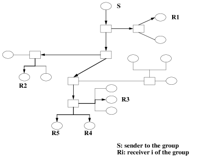
Figure 1: Establishing multicast delivery tree Multicast distribution trees may be established by either broadcast-and-prune or explicit join protocols. In the former, such as DVMRP or PIM-DM, a multicast packet is broadcast to all leaf subnetworks. Subnetworks with no local members for the group send prune messages towards the source(s) of the packets to stop further broadcasts. Link state protocols, such as MOSPF, broadcast membership information to all nodes. In contrast, in explicit join protocols, such as CBT or PIM-SM, routers send hop-by-hop join messages for the groups and sources for which they have local members.
We conduct robustness case studies for PIM-DM. We are particularly interested in multicast routing protocols, because they are vulnerable to failure modes, such as selective loss, that have not been traditionally studied in the area of protocol design.
For most multicast protocols, when routers are connected via a multi-access network (or LAN)222We use the term LAN to designate a connected network with respect to IP-multicast. This includes shared media (such as Ethernet, or FDDI), hubs, switches, etc., hop-by-hop messages are multicast on the LAN, and may experience selective loss; i.e. may be received by some nodes but not others. The likelihood of selective loss is increased by the fact that LANs often contain hubs, bridges, switches, and other network devices. Selective loss may affect protocol robustness.
Similarly, end-to-end multicast protocols and applications must deal with situations of selective loss. This differentiates these applications most clearly from their unicast counterparts, and raises interesting robustness questions.
Our case studies illustrate why selective loss should be considered when evaluating protocol robustness. This lesson is likely to extend to the design of higher layer protocols that operate on top of multicast and can have similar selective loss.
II Framework Overview
Protocols may be evaluated for correctness or performance. We refer to correctness studies that are conducted in the absence of network failures as verification. In contrast, robustness studies consider the presence of network failures (such as packet loss or crashes). In general, the robustness of a protocol is its ability to respond correctly in the face of network component failures and packet loss. This work presents a methodology for studying and evaluating multicast protocols, specifically addressing robustness and performance issues. We propose a framework that integrates automatic test generation as a basic component for protocol design, along with protocol modeling, simulation and implementation testing. The major contribution of this work lies in developing new methods for generating stress test scenarios that target robustness and correctness violation, or worst case performance.
Instead of studying protocol behavior in isolation, we incorporate the protocol model with network dynamics and failures in order to reveal more realistic behavior of protocols in operation.
This section presents an overview of the framework and its constituent components. The model used to represent the protocol and the system is presented along with definitions of the terms used.
Our framework integrates test generation with simulation and implementation code. It is used for Systematic Testing of Robustness by Evaluation of Synthesized Scenarios (STRESS). As the name implies, systematic methods for scenario synthesis are a core part of the framework. We use the term scenarios to denote the test-suite consisting of the topology and events.
The input to this framework is the specification of a protocol, and a definition of its design requirements, in terms of correctness or performance. Usually robustness is defined in terms of network dynamics or fault models. A fault model represents various component faults; such as packet loss, corruption, re-ordering, or machine crashes. The desired output is a set of test-suites that stress the protocol mechanisms according to the robustness criteria.
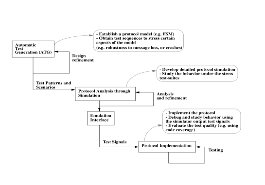
As shown in Figure 2, the STRESS framework includes test generation, detailed simulation driven by the synthesized tests, and protocol implementation driven through an emulation interface to the simulator. In this work we focus on the test generation (TG) component.
II-A Test Generation
The core contribution of our work lies in the development of systematic test generation algorithms for protocol robustness. We investigate two such algorithms, each using a different approach.
In general test generation may be random or deterministic. Generation of random tests is simple but a large set of tests is needed to achieve a high measure of error coverage. Deterministic test generation (TG), on the other hand, produces tests based on a model of the protocol. The knowledge built into the protocol model enables the production of shorter and higher-quality test sequences. Deterministic TG can be: a) fault-independent, or b) fault-oriented. Fault-independent TG works without targeting individual faults as defined by the fault model. Such an approach may employ a forward search technique to inspect the protocol state space (or an equivalent subset thereof), after integrating the fault into the protocol model. In this sense, it may be considered a variant of reachability analysis. We use the notion of equivalence to reduce the search complexity. Section IV describes our fault-independent approach.
In contrast, fault-oriented tests are generated for specified faults. Fault-oriented test generation starts from the fault (e.g. a lost message) and synthesizes the necessary topology and sequence of events that trigger the error. This algorithm uses a mix of forward and backward searches. We present our fault-oriented algorithm in Section V.
We conduct case studies for the multicast routing protocol PIM-DM to illustrate differences between the approaches, and provide a basis for comparison.
In the remainder of this section, we describe the system model and definition.
II-B The system model
We define our target system in terms of network and topology elements and a fault model.
II-B1 Elements of the network
Elements of the network consist of multicast capable nodes and bi-directional symmetric links. Nodes run same multicast routing, but not necessarily the same unicast routing. The topology is an -router LAN modeled at the network level; we do not model the MAC layer.
For end-to-end performance evaluation, the multicast distribution tree is abstracted out as delays between end systems and patterns of loss for the multicast messages. Cascade of LANs or uniform topologies are addressed in future research.
II-B2 The fault model
We distinguish between the terms error and fault. An error is a failure of the protocol as defined in the protocol design requirement and specification. For example, duplication in packet delivery is an error for multicast routing. A fault is a low level (e.g. physical layer) anomalous behavior, that may affect the behavior of the protocol under test. Note that a fault may not necessarily be an error for the low level protocol.
The fault model may include: (a) Loss of packets, such as packet loss due to congestion or link failures. We take into consideration selective packet loss, where a multicast packet may be received by some members of the group but not others, (b) Loss of state, such as multicast and/or unicast routing tables, due to machine crashes or insufficient memory resources, (c) The delay model, such as transmission, propagation, or queuing delays. For end-to-end multicast protocols, the delays are those of the multicast distribution tree and depend upon the multicast routing protocol, and (d) Unicast routing anomalies, such as route inconsistencies, oscillations or flapping.
Usually, a fault model is defined in conjunction with the robustness criteria for the protocol under study. For our robustness studies we study PIM. The designing robustness goal for PIM is to be able to recover gracefully (i.e. without going into erroneous stable states) from single protocol message loss. That is, being robust to a single message loss implies that transitions cause the protocol to move from one correct stable state to another, even in the presence of selective message loss. In addition, we study PIM protocol behavior in presence of crashes and route inconsistencies.
II-C Test Sequence Definition
A fault model may include a single fault or multiple faults. For our robustness studies we adopt a single-fault model, where only a single fault may occur during a scenario or a test sequence.
We define two sequences, and , where is an event and is a fault. Let be the sequence of states and stimuli of protocol under test starting from the initial state . is a test sequence if final is incorrect; i.e. the stable state reached after the occurrence of the fault does not satisfy the protocol correctness conditions (see Section II-E) irrespective of . In case of a fault-free sequence, where , the error is attributed to a protocol design error. Whereas when , and final is correct, the error is manifested by the fault. This definition ignores transient protocol behavior. We are only concerned with the stable (i.e. non-transient) behavior of a protocol.
II-D Test Scenario
A test scenario is defined by a sequence of (host) events, a topology, and a fault model, as shown in Figure 3.

The events are actions performed by the host and act as input to the system; for example, join, leave, or send packet. The topology is the routed topology of set of nodes and links. The nodes run the set of protocols under test or other supporting protocols. The links can be either point-to-point links or LANs. This model may be extended later to represent various delays and bandwidths between pairs of nodes, by using a virtual LAN matrix (see [10]). The fault model used to inject the fault into the test. According to our single-message loss model, for example, a fault may denote the ‘loss of the second message of type traversing a certain link’. Knowing the location and the triggering action of the fault is important in analyzing the protocol behavior.
II-E Brief description of PIM-DM
For our robustness studies, we apply our automatic test generation algorithms to a version of the Protocol Independent Multicast-Dense Mode, or PIM-DM. The description given here is useful for Sections III through V.
PIM-DM uses broadcast-and-prune to establish the multicast distribution trees. In this mode of operation, a multicast packet is broadcast to all leaf subnetworks. Subnetworks with no local members send prune messages towards the source(s) of the packets to stop further broadcasts.
Routers with new members joining the group trigger Graft messages towards previously pruned sources to re-establish the branches of the delivery tree. Graft messages are acknowledged explicitly at each hop using the Graft-Ack message.
PIM-DM uses the underlying unicast routing tables to get the next-hop information needed for the RPF (reverse-path-forwarding) checks. This may lead to situations where there are multiple forwarders for a LAN. The Assert mechanism prevents these situations and ensures there is at most one forwarder for a LAN.
The correct function of a multicast routing protocol in general, is to deliver data from senders to group members (only those that have joined the group) without any data loss. For our methods, we only assume that a correctness definition is given by the protocol designer or specification. For illustration, we discuss the protocol errors and the correctness conditions.
II-E1 PIM Protocol Errors
In this study we target protocol design and specification errors. We are interested mainly in erroneous stable (i.e. non-transient) states. In general, the protocol errors may be defined in terms of the end-to-end behavior as functional correctness requirements. In our case, for PIM-DM, an error may manifest itself in one of the following ways:
1) black holes: consecutive packet loss between periods of packet delivery, 2) packet looping: the same packet traverses the same set of links multiple times, 3) packet duplication: multiple copies of the same packet are received by the same receiver(s), 4) join latency: lack of packet delivery after a receiver joins the group, 5) leave latency: unnecessary packet delivery after a receiver leaves the group 333Join and leave latencies may be considered in other contexts as performance issues. However, in our study we treat them as errors., and 6) wasted bandwidth: unnecessary packet delivery to network links that do not lead to group members.
II-E2 Correctness Conditions
We assume that correctness conditions are provided by the protocol designer or the protocol specification. These conditions are necessary to avoid the above protocol errors in a LAN environment, and include 444These are the correctness conditions for stable states; i.e. not during transients, and are defined in terms of protocol states (as opposed to end point behavior). The mapping from functional correctness requirements for multicast routing to the definition in terms of the protocol model is currently done by the designer. The automation of this process is part of future research.:
-
1.
If one (or more) of the routers is expecting to receive packets from the LAN, then one other router must be a forwarder for the LAN. Violation of this condition may lead to data loss (e.g. join latency or black holes).
-
2.
The LAN must have at most one forwarder at a time. Violation of this condition may lead to data packet duplication.
-
3.
The delivery tree must be loop-free:
-
(a)
Any router should accept packets from one incoming interface only for each routing entry. This condition is enforced by the RPF (Reverse Path Forwarding) check.
-
(b)
The underlying unicast topology should be loop-free 555Some esoteric scenarios of route flapping may lead to multicast loops, in spite of RPF checks. Currently, our study does not address this issue, as it does not pertain to a localized behavior..
Violation of this condition may lead to data packet looping.
-
(a)
-
4.
If one of the routers is a forwarder for the LAN, then there must be at least one router expecting packets from the LANs. Violation of this condition may lead to leave latency.
III Search-based Approaches
The problem of test synthesis can be viewed as a search problem. By searching the possible sequences of events and faults over network topologies and checking for design requirements (either correctness or performance), we can construct the test scenarios that stress the protocol. However, due to the state space explosion, techniques must be used to reduce the complexity of the space to be searched. We attempt to use these techniques to achieve high test quality and protocol coverage.
Following we present the GFSM model for the case study protocol (PIM-DM), and use it as an illustrative example to analyze the complexity of the state space and the search problem, as well as illustrate the algorithmic details and principles involved in FITG and FOTG.
III-A The Protocol Model
We represent the protocol as a finite state machine (FSM) and the overall LAN system by a global FSM (GFSM).
I. FSM model: Every instance of the protocol, running on a single router, is modeled by a deterministic FSM consisting of: (i) a set of states, (ii) a set of stimuli causing state transitions, and (iii) a state transition function (or table) describing the state transition rules. For a system , this is represented by the machine , where is a finite set of state symbols, is the set of stimuli, and is the state transition function .
II. Global FSM model: The global state is defined as the composition of individual router states. The output messages from one router may become input messages to other routers. Such interaction is captured by the GFSM model in the global transition table. The behavior of a system with routers may be described by , where : is the global state space, : is the set of stimuli, and is the global state transition function .
The fault model is integrated into the GFSM model. For message loss, the transition caused by the message is either nullified or modified, depending on the selective loss pattern. Crashes may be treated as stimuli causing the routers affected by the crash to transit into a state 666The state maybe one of the states already defined for the protocol, like the state, or may be a new state that was not defined previously for the protocol.. Network delays are modeled (when needed) through the delay matrix presented in Section VII.
III-B PIM-DM Model
Following is the model of a simplified version of PIM-DM.
III-B1 FSM model
For a given group and a given source (i.e., for a specific source-group pair), we define the states w.r.t. a specific LAN to which the router is attached. For example, a state may indicate that a router is a forwarder for (or a receiver expecting packets from) the LAN.
System States ()
Possible states in which a router may exist are:
| State Symbol | Meaning |
|---|---|
| Router is a forwarder for the LAN | |
| forwarder with Timer Timer running | |
| Upstream router a non-forwarder | |
| Router has the LAN as its next-hop | |
| same as with Timer Timer running | |
| Router has a negative-cache entry | |
| Upstream router is empty | |
| Downstream router is empty | |
| Downstream router with attached member | |
| Downstream router with no members |
The possible states for upstream and downstream routers are as follows:
Stimuli ()
The stimuli considered here include transmitting and receiving protocol messages, timer events, and external host events. Only stimuli leading to change of state are considered. For example, transmitting messages per se (vs. receiving messages) does not cause any change of state, except for the , in which case the timer is set. Following are the stimuli considered in our study:
1. Transmitting messages: Graft transmission ().
2. Receiving messages: Graft reception (), Join reception (), Prune reception (), Graft Acknowledgement reception (), Assert reception (), and forwarded packets reception ().
3. Timer events: these events occur due to timer expiration () and include the Graft re-transmission timer (), the event of its expiration (), the forwarder-deletion timer (), and the event of its expiration (). We refer to the event of timer expiration as ().
4. External host events (): include host sending packets (), host joining a group ( or ), and host leaving a group ( or ).
.
III-B2 Global FSM model
Subscripts are added to distinguish different routers. These subscripts are used to describe router semantics and how routers interact on a LAN. An example global state for a topology of 4 routers connected to a LAN, with router 1 as a forwarder, router 2 expecting packets from the LAN, and routers 3 and 4 have negative caches, is given by . For the global stimuli , subscripts are added to stimuli to denote their originators and recipients (if any). The global transition rules are extended to encompass the router and stimuli subscripts 777Semantics of the global stimuli and global transitions will be described as needed (see Section V)..
III-C Defining stable states
We are concerned with stable state (i.e. non-transient) behavior, defined in this section. To obtain erroneous stable states, we need to define the transition mechanisms between such states. We introduce the concept of transition classification and completion to distinguish between transient and stable states.
III-C1 Classification of Transitions
We identify two types of transitions; externally triggered (ET) and internally triggered (IT) transitions. The former is stimulated by events external to the system (e.g., or ), whereas the latter is stimulated by events internal to the system (e.g., or ).
We note that some transitions may be triggered due to either internal and external events, depending on the scenario. For example, a may be triggered due to forwarding packets by an upstream router (which is an internal event), or a (which is an external event).
A global state is checked for correctness at the end of an externally triggered transition after completing its dependent internally triggered transitions.
Following is a table of host events, their dependent ET and IT events:
| Host Events | |||
|---|---|---|---|
| ET events | |||
| IT events | , , | ||
III-C2 Transition Completion
To check for the global system correctness, all stimulated internal transitions should be completed, to bring the system into a stable state. Intermediate (transient) states should not be checked for correctness (since they may temporarily seem to violate the correctness conditions set forth for stable states, and hence may give false error indication). The process of identifying complete transitions depends on the nature of the protocol. But, in general, we may identify a complete transition sequence, as the sequence of (all) transitions triggered due to a single external stimulus (e.g., or ). Therefore, we should be able to identify a transition based upon its stimuli (either external or internal). At the end of each complete transition sequence the system exists in either a correct or erroneous stable state. Event-triggered timers (e.g., , ) fire at the end of a complete transition.
III-D Problem Complexity
The problem of finding test scenarios leading to protocol error can be viewed as a search problem of the protocol state space. Conventional reachability analysis [11] attempts to investigate this space exhaustively and incurs the ’state space explosion’ problem. To circumvent this problem we use search reduction techniques using domain-specific information of multicast routing.
In this section, we give the complexity of exhaustive search, then discuss the reduction techniques we employ based on notion of equivalence, and give the complexity of the state space.
III-D1 Complexity of exhaustive search
Exhaustive search attempts to generate all states reachable from initial system states. For a system of routers where each router may exist in any state , and states, the number of reachable states in the system is bounded by . With possible transitions we need state visits to investigate all transitions. Faults, such as message loss and crashes, increase the branching factor , and may introduce new states increasing . For our case study , while selective loss and crashes 888Crashes force any state to the empty state. increase branching almost by factor of 9.
III-D2 State reduction through equivalence
Exhaustive search has exponential complexity. To reduce this complexity we use the notion of equivalence. Intuitively, in multicast routing the order in which the states are considered is irrelevant (e.g., if router or is a forwarder is insignificant, so long as there is only one forwarder). Hence, we can treat the global state as an unordered set of state symbols. This concept is called ‘counting equivalence’ 999Two system states () and ( are strictly equivalent iff , where . However, all routers use the same deterministic FSM model, hence all permutations of () are equivalent. A global state for a system with routers may be represented as , where is the number of routers in state and . Formally, Counting Equivalence states that two system states and are equivalent if .. By definition, the notion of equivalence implies that by investigating the equivalent subspace we can test for protocol correctness. That is, if the equivalent subspace is verified to be correct then the protocol is correct, and if there is an error in the protocol then it must exist in the equivalent subspace 101010The notion of counting equivalence also applies to transitions and faults. Those transitions or faults leading to equivalent states are considered equivalent..
Symbolic representation
We use a symbolic representation as a convenient form of representing the global state to illustrate the notion of equivalence and to help in defining the error and correct states in a succinct manner. In the symbolic representation, routers in state are represented by . The global state for a system of routers is represented by , where , . For symbolic representation of topologies where is unknown (‘1+’ is 1 or more, and ‘*’ is 0 or more).
To satisfy the correctness conditions for PIM-DM, the correct stable global states are those containing no forwarders and no routers expecting packets, or those containing one forwarder and one or more routers expecting packets from the link; symbolically this may be given by: , and . 111111For convenience, we may represent these two states as , and .
We use to denote state . For example, denotes 0 or more states . This symbolic representation is used to estimate the size of the reduced state space.
Complexity of the state space with equivalence reduction
Considering counting equivalence, finding the number of equivalent states becomes a problem of combinatorics. The number of equivalent states becomes , where, is the number of routers, is the number of state symbols, and , is the number of -combination of -set [12].
III-D3 Representation of error and correct states
Depending on the correctness definition we may get different counts for the number of correct or error states. To get an idea about the size of the correct or error state space for our case study, we take two definitions of correctness and compute the number of correct states. For the correct states of PIM-DM, we either have: (1) no forwarders with no routers expecting packets from the LAN, or (2) exactly one forwarder with routers expecting packets from the LAN 121212These conditions we have found to be reasonably sufficient to meet the functional correctness requirements. However, they may not be necessary, hence the search may generate false errors. Proving necessity is part of future work..
The correct space and the erroneous space must be disjoint and they must be complete (i.e. add up to the complete space), otherwise the specification is incorrect. See Appendix I-A for details.
We present two correctness definitions that are used in our case.
-
•
The first definition considers the forwarder states as and the routers expecting packets from the LAN as . Hence, the symbolic representation of the correct states becomes: , or ,
and the number of correct states is:
-
•
The second definition considers the forwarder states as or simply , and the states expecting packets from the LAN as or simply . Hence, the symbolic representation of the correct states becomes: , or ,
and the number of correct states is:
Refer to Appendix I-B for more details on deriving the number of correct states.
In general, we find that the size of the error state space, according to both definitions, constitutes the major portion of the whole state space. This means that search techniques explicitly exploring the error states are likely to be more complex than others. We take this in consideration when designing our methods.
IV Fault-independent Test Generation
Fault-independent test generation (FITG) uses the forward search technique to investigate parts of the state space. As in reachability analysis, forward search starts from initial states and applies the stimuli repeatedly to produce the reachable state space (or part thereof). Conventionally, an exhaustive search is conducted to explore the state space. In the exhaustive approach all reachable states are expanded until the reachable state space is exhausted. We use several manifestations of the notion of counting equivalence introduced earlier to reduce the complexity of the exhaustive algorithm and expand only equivalent subspaces. To examine robustness of the protocol, we incorporate selective loss scenarios into the search.
IV-A Reduction Using Equivalences
The search procedure starts from the initial states 131313For our case study the routers start as either a non-member () or empty upstream routers (), that is, the initial states . and keeps a list of states visited to prevent looping. Each state is expanded by applying the stimuli and advancing the state machine forward by implementing the transition rules and returning a new stable state each time 141414For details of the above procedures, see Appendix II-A.. We use the counting equivalence notion to reduce the complexity of the search in three stages of the search:
-
1.
The first reduction we use is to investigate only the equivalent initial states. To achieve this we simply treat the set of states constituting the global state as unordered set instead of ordered set. For example, the output of such procedure for and would be: .
One procedure that produces such equivalent initial state space given in Appendix II-B. The complexity of the this algorithm is given by as was shown in Section III-D2 and verified through simulation.
-
2.
The second reduction we use is during comparison of visited states. Instead of comparing the actual states, we compare and store equivalent states. Hence, for example, the states and are equivalent.
-
3.
A third reduction is made based on the observation that applying identical stimuli to different routers in identical states leads to equivalent global states. Hence, we can eliminate some redundant transitions. For example, for the global state a applied to or would produce the equivalent state . To achieve this reduction we add flag check before advancing the state machine forward. We call the algorithm after the third reduction the reduced algorithm.
In all the above algorithms, a forward step advances the GFSM to the next stable state. This is done by applying all the internally dependent stimuli (elicited due to the applied external stimulus) in addition to any timer implications, if any exists. Only stable states are checked for correctness.
IV-B Applying the Method
In this section we discuss how the fault-independent test generation can be applied to the model of PIM-DM. We apply forward search techniques to study correctness of PIM-DM. We first study the complexity of the algorithms without faults. Then we apply selective message loss to study the protocol behavior and analyze the protocol errors.
IV-B1 Method input
The protocol model is provided by the designer or protocol specification, in terms of a transition table or transition rules of the GFSM, and a set of initial state symbols. The design requirements, in terms of correctness in this case, is assumed to be also given by the protocol specification. This includes definition of correct states or erroneous states, in addition to the fault model if studying robustness. Furthermore, the detection of equivalence classes needs to be provided by the designer 151515For our case study, the symmetry inherent in multicast over LANs was used to establish the counting equivalence for states, transitions and faults.. Currently, we do not automate the detection of equivalent classes. Also, the number of routers in the topology or topologies to be investigated (i.e., on the LAN) has to be specified.
IV-B2 Complexity of forward search for PIM-DM
The procedures presented above were simulated for PIM-DM to study its correctness. This set of results shows behavior of the algorithms without including faults, i.e., when used for verification. We identified the initial state symbols to be ; for downstream routers and for upstream routers. The number of reachable states visited, the number of transitions and the number of erroneous states found were recorded. Summary of the results is given in Figure 4. The number of expanded states denotes the number of visited stable states. The number of ‘forwards’ is the number of times the state machine was advanced forward denoting the number of transitions between stable states. The number of transitions is the number of visited transient states, and the number of error states is the number of stable (or expanded) states violating the correctness conditions. The error condition is given as in the second error condition in Section III-D3. Note that each of the other error states is equivalent to at least one error state detected by the reduced algorithm. Hence, having less number of discovered error states by an algorithm in this case does not mean losing any information or causes of error, which follows from the definition of equivalence. Reducing the error states means reducing the time needed to analyze the errors.
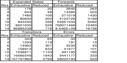
We notice that there significant reduction in the algorithm complexity with the use of equivalence relations. In particular, the number of transitions is reduced from for the exhaustive algorithm, to for the reduced algorithm. Similar results were obtained for the number of forwards, expanded states and number of error states. The reduction gained by using the counting equivalence is exponential. More detailed presentation of the algorithmic details and results are given in Appendix II.
For robustness analysis (vs. verification), faults are included in the GFSM model. Intuitively, an increase in the overall complexity of the algorithms will be observed. Although we have only applied faults to study the behavior of the protocol and not the complexity of the search, we anticipate similar asymptotic reduction gains using counting equivalence.
IV-B3 Summary of behavioral errors for PIM-DM
We used the above algorithm to search the protocol model for PIM-DM. Correctness was checked automatically by the method by checking the stable states (i.e., after applying complete transitions). By analyzing the sequence of events leading to error we were able to reason about the protocol behavior. Several PIM-DM errors were detected by the method, some pertaining to correctness in the absence of message loss, while others were only detected in the presence of message loss. We have studied cases of up to 14-router LANs. Sometimes errors were found to occur in different topologies for similar reasons as will be shown. Here, we only discuss results for the two router and 3-router LAN cases for illustration.
-
•
Only one error was detected in the two-router case. With the initial state (i.e., both routers are upstream routers), the system enters the error state , where there is a forwarder for the LAN but there are no routers expecting packets or attached members. In this case the process chose one forwarder for the LAN, but there were no downstream routers to off the extra traffic, and so the protocol causes wasted bandwidth.
-
•
Several errors were detected for the 3-router LAN case:
-
–
Starting from the system enters the error state for a similar reason to that given above.
-
–
Starting from the system enters the error state . By analyzing the trace of events leading to the error we notice that the downstream router pruned off one of the upstream routers, , before the process takes place to choose a winner for the LAN. Hence the protocol causes wasted bandwidth.
-
–
Starting from the system enters state . This is due to the transition table rules, when a forwarder sends a packet, all upstream routers in the state transit into state. This is not an actual error, however, since the system will recover with the next forwarded packet using 161616This is one case where the correctness conditions for the model are sufficient but not necessary to meet the functional requirements for correctness, thus leading to a false error. Sufficiency and necessity proofs are subject of future work.. The detection of this false-error could have been avoided by issuing stimulus before the error check, to see if the system will recover with the next packet sent.
-
–
With message loss, errors were detected for and loss. When the system is in state and one of the downstream members leaves (i.e., issues event), a is sent on the LAN. If this is selectively lost by the other downstream router, a will not be sent and the system enters state . Similarly, if the is lost, the protocol ends up in an error state.
-
–
IV-C Challenges and Limitations
In order to generalize the fault-independent test generation method, we need to address several open research issues and challenges.
-
•
The topology is an input to the method in terms of number of routers. To add topology synthesis to FITG we may use the symbolic representation presented in Section III-D, where the use of repetition constructs 171717Repetition constructs include, for example, the ‘*’ to represent zero or more states, or the ‘1+’ to represent one or more states, ‘2+’ two or more, so on. may be used to represent the LAN topology in general. A similar principle was used in [13] for cache coherence protocol verification, where the state space is split using repetition constructs based on the correctness definition. In Section V we present a new method that synthesizes the topology automatically as part of the search process.
-
•
Equivalence classes are given as input to the method. In this study we have used symmetries inherent in multicast routing on LANs to utilize equivalence. This symmetry may not exist in other protocols or topologies, hence the forward search may become increasingly complex. Automating identification of equivalence classes is part of future work.
Other kinds of equivalence may be investigated to reduce complexity in these cases 181818An example of another kind of equivalence is fault dominance, where a system is proven to necessarily reach one error before reaching another, thus the former error dominates the latter error.. Also, other techniques for complexity reduction may be investigated, such as statistical sampling based on randomization or hashing used in SPIN [14]. However, sampling techniques do not achieve full coverage of the state space.
-
•
The topology used in this study is limited to a single-hop LAN. Although we found it quite useful to study multicast routing over LANs, the method needs to be extended to multi-hop LAN to be more general. Our work in [10] introduces the notion of LAN, and future work addresses multi-LAN topologies.
In sum, the fault-independent test generation may be used for protocol verification given the symmetry inherent in the system studied (i.e., protocol and topology). For robustness studies, where the fault model is included in the search, the complexity of the search grows. In this approach we did not address performance issues or topology synthesis. These issues are addressed in the coming sections. However, we shall re-use the notion of forward search and the use of counting equivalence in the method discussed next.
V Fault-oriented Test Generation
In this section, we investigate the fault-oriented test generation (FOTG), where the tests are generated for specific faults. In this method, the test generation algorithm starts from the fault(s) and searches for a possible error, establishing the necessary topology and events to produce the error. Once the error is established, a backward search technique produces a test sequence leading to the erroneous state, if such a state is reachable. We use the FSM formalism presented in Section III to represent the protocol. We also re-use some ideas from the FITG algorithm previously presented, such as forward search and the notion of equivalence for search reduction.
V-A FOTG Method Overview
Fault-oriented test generation (FOTG) targets specific faults or conditions, and so is better suited to study robustness in the presence of faults in general. FOTG has three main stages: a) topology synthesis, b) forward implication and error detection, and c) backward implication. The topology synthesis establishes the necessary components (e.g., routers and hosts) of the system to trigger the given condition (e.g., trigger a protocol message). This leads to the formation of a global state in the middle of the state space 191919The global state from which FOTG starts is synthesized for a given fault, such as a message to be lost.. Forward search is then performed from that global state in its vicinity, i.e., within a complete transition, after applying the fault. This process is called forward implication, and uses search techniques similar to those explained earlier in Section IV. If an error occurs, backward search is performed thereafter to establish a valid sequence leading from an initial state to the synthesized global state. To achieve this, the transition rules are reversed and a search is performed until an initial state is reached, or the synthesized state is declared unreachable. This process is called backward implication.
Much of the algorithmic details are based on reasoning of the transition rules. This reasoning is emphasized in the semantics of the transition table used in the topology synthesis and the backward search. Section V-A1 describes these semantics. In Section V-B we describe the algorithmic details of FOTG, and in Section V-C we describe how FOTG was applies to PIM-DM in our case study, and present the results and method evaluation. Section V-D we discuss the limitations of the method and our findings.
V-A1 The Transition Table
The global state transition may be represented in several ways. Here, we choose a transition table representation that emphasizes the effect of the stimuli on the system, and hence facilitates topology synthesis. The transition table describes, for each stimulus, the conditions of its occurrence. A condition is given as stimulus and state or transition (denoted by stimulus.state/trans), where the transition is given as .
We further extend message and router semantics to capture multicast semantics. Following, we present a detailed description of the semantics of the transition table then give the resulting transition table for our case study, to be used later in this section.
Semantics of the transition table
In this subsection we describe the message and router semantics, pre-conditions, and post-conditions.
-
•
Stimuli and router semantics: Stimuli are classified based on the routers affected by them. Stimuli types include:
-
1.
: stimuli or events occurring within the router originating the stimulus but do not affect other routers, and include , , , , and .
-
2.
: messages that are processed by the destination router only, and include , and .
-
3.
: multicast messages that are processed by all other routers, and include and .
-
4.
: multicast messages that are processed by all other downstream routers, but only one upstream router, and includes the message.
These types are used by the search algorithm for processing the stimuli and messages. According to these different types of stimuli processing a router may take as subscript ‘’, ‘’, or ‘’. The ‘’ symbol designates the originating router of the stimulus or message, whereas ‘’ designates the destination of the message. ‘’ indicates routers other than the originator. Routers are also classified as or as presented in Section III.
-
1.
-
•
Pre-Conditions: The pre-conditions in general are of the form , where the transition is given as . If there are several pre-conditions, then we can use a logical OR to represent the rule. At least one pre-condition is necessary to trigger the stimulus. Example of a condition is the condition for message, namely, , that is, a is triggered by the reception of a from another router, with the originator of the in . An example of a condition is the condition for Graft transmission ; i.e. a host joining and the transition of the router from the negative cache state to the next hop state.
-
•
Post-Conditions: A post-condition is an event and/or transition that is triggered by the stimulus. 202020Network faults, such as message loss, may cause the stimulus not to take effect. For example, losing a message will cause the event of reception not to take effect. Post-conditions may be in the form of: (1) , (2) , (3) , and (4) .
-
1.
: has an implicit condition with which it is associated; i.e. ‘’ means ‘if then ’. For example, post-condition (), means if then transition will occur.
-
2.
: is same as (1) except the condition is explicit 212121This does not appear in our case study..
-
3.
: if the condition is satisfied then the stimulus is triggered. For example, post-condition ‘’, means that for all (where is not equal to ) then have router trigger a .
-
4.
: has the transition condition implied as in (1) above. For example, post-condition ‘’, means if , then the transition occurs and is triggered.
If more than one post-condition exists, then the logical relation between them is either an ‘XOR’ if the router is the same, or an ‘AND’ if the routers are different. For example, post-conditions are ‘’, which means () XOR (). 222222There is an implicit condition that can never be satisfied in both statements, which is the existence of in only one state at a time.
On the other hand, post-conditions are ‘’, which implies that the transition will occur if AND a will be triggered if .
-
1.
Following is the transition table used in our case study.
| Stimulus | Pre-conditions | Post-conditions |
|---|---|---|
| , | ||
| RtxExp | ||
| DelExp | ||
| Ext | ||
| Ext | ||
| Ext | ||
The above pre-conditions can be derived automatically from the post-conditions. In Appendix III, we describe the ‘PreConditions’ procedure that takes as input one form of the conventional post-condition transition table and produces the pre-condition semantics.
State Dependency Table
To aid in test sequence synthesis through the backward implication procedure, we construct what we call a state dependency table. This table can be inferred automatically from the transition table. We use this table to improve the performance of the algorithm and for illustration.
For each state, the dependency table contains the possible preceding states and the stimulus from which the state can be reached or implied. To obtain this information for a state , the algorithm the post-conditions of the transition table for entries where the of a transition is . In addition, a state may be identified as an initial state (I.S.), and hence can be readily established without any preceding states. The ‘dependencyTable’ procedure in Appendix III generates the dependency table from the transition table of conditions. For a symbol denoting initial state is added to the array entry. For our case study . Based on the above transition table, following is the resulting state dependency table: 232323The possible backward implications are separated by ‘commas’ indicating ‘OR’ relation.
—l—l—
State & Possible Backward Implication(s)
In cases where the stimulus affects more than one router (e.g., multicast ), multiple states need to be simultaneously implied in one backward step, otherwise an may not be reached. To do this, the transitions in the post-conditions of the stimulus are traversed, and any states in the global state that are s are replaced by their corresponding s. For example, . This is taken care of by the backward implication section described later.
V-B FOTG details
As previously mentioned, our FOTG approach consists of three phases: I) synthesis of the global state to inspect, II) forward implication, and III) backward implication. These phases are explained in more detail in this section. In Section V-C we present an illustrative example for the these phases.
V-B1 Synthesizing the Global State
Starting from a condition (e.g., protocol message or stimulus), and using the information in the protocol model (i.e. the transition table), a global state is synthesized for investigation. We refer to this state as the global-state inspected (), and it is obtained as follows:
-
1.
The global state is initially empty and the inspected stimulus is initially set to the stimulus investigated.
-
2.
For the inspected stimulus, the state(s) (or the (s) of the transition) of the post-condition are obtained from the transition table. If these states do not exist in the global state, and cannot be inferred therefrom, then they are added to the global state.
-
3.
For the inspected stimulus, the state(s) (or the (s) of the transition) of the pre-condition are obtained. If these states do not exist in the global state, and cannot be inferred therefrom, then they are added to the global state.
-
4.
Get the stimulus of the pre-condition of the inspected stimulus, call it . If is not external (), then set the inspected stimulus to the , and go back to step 2.
The second step considers post-conditions and adds system components that will be affected by the stimulus. While the third and forth steps synthesize the components necessary to trigger the stimulus. The procedure given in Appendix III synthesizes minimum topologies necessary to trigger a given stimulus of the protocol.
Note that there may be several pre-conditions or post-conditions for a stimulus, in which case several choices can be made. These represent branching points in the search space. At the end of this stage, the global state to be investigated is obtained.
V-B2 Forward Implication
The states following (i.e. where ) are obtained through forward implication. We simply apply the transitions, starting from , as given by the transition table, in addition to implied transitions (such as timer implication). Furthermore, faults are incorporated into the search. For example, in the case of a message loss, the transition that would have resulted from the message is not applied. If more than one state is affected by the message, then the space is expanded to include the various selective loss scenarios for the affected routers. For crashes, the routers affected by the crash transit into the crashed state as defined by the expanded transition rules, as will be shown in Section V-C. Forward implication uses the forward search techniques described earlier in Section IV.
According to the transition completion concept (see Section III-C2), the proper analysis of behavior should start from externally triggered transitions. For example, the analysis should not consider a without considering the triggering it and its effects on the system. Thus, the global system state must be rolled back to the beginning of a complete transition (i.e. the previous stable state) before applying the forward implication. This will be implied in the forward implication algorithm to simplify the discussion.
V-B3 Backward Implication
Backward implication attempts to obtain a sequence of events leading to , from an initial state (), if such a sequence exists; i.e. if is reachable from
The state dependency table described in Section V-A1 is used in the backward search.
Backward steps are taken for the components in the global state , each step producing another global state . For each state in possible backward implication rules are attempted to obtain valid backward steps toward an initial state. This process is repeated for preceding states in a depth first fashion. A set of visited states is maintained to avoid looping. If all backward branches are exhausted and no initial state was reached the state is declared unreachable.
To rewind the global state one step backward, the reverse transition rules are applied. Depending on the stimulus type of the backward rule, different states in are rolled back. For and only the originator and destination of the stimulus is rolled back, respectively. For , all affected states are rolled back except the originator. is similar to except that all downstream routers or states are rolled back, while only one upstream router (the destination) is rolled back. Appendix III shows procedures ‘Backward’ and ‘Rewind’ that implement the above steps.
Note, however, that not all backward steps are valid, and backtracking is performed when a backward step is invalid. Backtracking may occur when the preceding states contradict the rules of the protocol. These contradictions may manifest themselves as:
-
•
not found: is the originator of the stimulus, and the global state has to include at least one component to originate the stimulus. An example of this contradiction occurs for the stimulus, for a global state , where the an originating component of the ( in this case) does not belong to the global state.
-
•
Failure of minimum topology check: the necessary conditions to trigger the stimulus must be present in the global topology. Examples of failing the minimum topology check include, for instance, stimulus with global state , or stimulus with global state .
-
•
Failure of consistency check: to maintain consistency of the transition rules in the reverse direction, we must check that every backward step has an equivalent forward step. To achieve this, we must check that there is no transition for the given stimulus, such that . Since if remains in the preceding global state, the corresponding forward step would transform into and the system would exist in a state inconsistent with the initial global state (before the backward step). An example of this inconsistency exists when the stimulus is and , where is a post condition for . See Appendix III for the consistency check procedure.
V-C Applying The Method
In this section we discuss how the fault-oriented test generation can be applied to the model of PIM-DM. Specifically, we discuss in details the application of FOTG to the robustness analysis of PIM-DM in the presence of single message loss and machine crashes. We first walk through a simple illustrative example. Then we present the results of the case study in terms of correctness violations captured by the method.
V-C1 Method input
The protocol model is provided by the designer or protocol specification, in terms of a transition table 242424The traditional input/output transition table is sufficient for our method. The pre/post-condition transition table can be derived automatically therefrom., and the semantics of the messages. In addition, a list of faults to be studied is given as input to the method. For example, definition of the fault as single selective protocol message loss, applied to the list of messages . Also a set of initial state symbols, in our case . A definition of the design requirement, in this case definition of correctness, is also provided by the specification. The rest of the process is automated.
V-C2 Illustrative example
Figure 5 shows the phases of FOTG for a simple example of a loss. Following are the steps taken for that example:
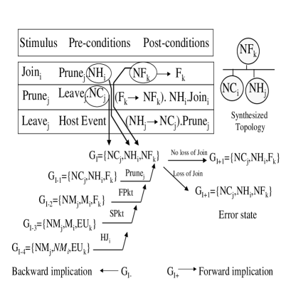
| Synthesizing the Global State |
|---|
| 1. : of post-condition is |
| 2. : state of pre-condition is , goto |
| 3. : of post-condition is , implied from in |
| 4. : state of pre-condition is , goto (Ext) |
| 5. of post-condition is can be implied from in |
| Forward implication |
|---|
| without loss: |
| loss w.r.t. : error |
| Backward implication |
|---|
Losing the by the forwarding router leads to an error state where router is expecting packets from the LAN, but the LAN has no forwarder.
V-C3 Summary of Results
In this section we briefly discuss the results of applying our method to PIM-DM. The analysis is conducted for single message loss and momentary loss of state. For a detailed analysis of the results see Appendix III-G.
Single message loss
We have studied single message loss scenarios for the and messages. For this subsection, we mostly consider non-interleaved external events, where the system is stimulated only once between stable states. The message is particularly interesting, since it is acknowledged, and it raises timing and sequencing issues that we address in a later subsection, where we extend our method to consider interleaving of external events.
Our method as presented here, however, may not be generalized to transform any type of timing problem into sequencing problem. This topic bears more research in the future.
We have used the sequences of events generated automatically by the algorithm to analyze protocol errors and suggest fixes for those errors.
Join: A scenario similar to that presented in Section V-C2 incurred an error. In this case, the robustness violation was not allowing another chance to the downstream router to send a . A suggested fix would be to send another prune by before the timer expires.
Prune: In the topology above, an error occurs when loses the , hence no is triggered. The fix suggested above takes care of this case too.
Assert: An error in the case occurs with no downstream routers; e.g. . The design error is the absence of a mechanism to prevent pruning packets in this case. One suggested fix would be to have the winner schedule a deletion timer (i.e. becomes ) and have the downstream receiver (if any) send to the winner.

Graft: A message is acknowledged by , hence the protocol did not incur error when the message was lost with non-interleaved external events. The protocol is robust to loss with the use of timer. Adversary external conditions are interleaved during the transient states and the timer is cleared, such that the adverse event will not be overridden by the mechanism.
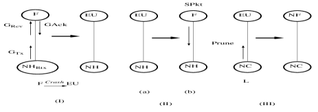
To clear the timer, a transition should be created from to which is triggered by a according to the state dependency table (). This transition is then inserted in the event sequence, and forward and backward implications are used to obtain the overall sequence of events illustrated in Figure 6. In the first and second scenarios (I and II) no error occurs. In the third scenario (III) when a followed by a is interleaved with the loss, the timer is reset with the receipt of the for the first , and the systems ends up in an error state. A suggested fix is to add sequence numbers to s, at the expense of added complexity.
Loss of State
We consider momentary loss of state in a router. A ‘’ stimulus transfers the crashed router from any state ‘X’ into ‘EU’ or ‘ED’. Hence, we add the following line to the transition table:
| Stimulus | Pre-cond | Post-cond (stimulus.state/trans) |
|---|---|---|
| Ext | , | |
The FSM resumes function immediately after the crash (i.e. further transitions are not affected). We analyze the behavior when the crash occurs in any router state. For every state, a topology is synthesized that is necessary to create that state. We leverage the topologies previously synthesized for the messages. For example, state may be created from state by receiving a (). Hence we may use the topologies constructed for loss to analyze a crash for state.
Forward implication is then applied, and behavior after the crash is checked for correct packet delivery. To achieve this, host stimuli (i.e. , and ) are applied, then the system state is checked for correctness.
In lots of the cases studied, the system recovered from the crash (i.e. the system state was eventually correct). The recovery is mainly due to the nature of PIM-DM; where protocol states are re-created with reception of data packets. This result is not likely to extend to protocols of other natures; e.g. PIM Sparse-Mode [15].
However, in violation with robustness requirements, there existed cases in which the system did not recover. In Figure 7, the host joining in (II, a) did not have the sufficient state to send a and hence gets join latency until the negative cache state times out upstream and packets are forwarded onto the LAN as in (II, b).
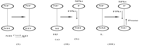
In Figure 8 (II, a), the downstream router incurs join latency due to the crash of the upstream router. The state is not corrected until the periodic broadcast takes place, and packets are forwarded onto the LAN as in (II, b).
V-D Challenges and Limitations
Although we have been able to apply FOTG to PIM-DM successfully, a discussion of the open issues and challenges is called for. In this section we address some of these issues.
-
•
The topologies synthesized by the above FOTG study are only limited to a single-hop LAN with routers 252525This limitation is similar to that suffered by FITG in Section IV.. This means that the above FOTG analysis is necessary but not sufficient to verify robustness of the end-to-end behavior of the protocol in a multi-hop topology; even if each LAN in the topology operates correctly, the inter-LAN interaction may introduce erroneous behaviors. Applying FOTG to multi-hop topologies is part of future research.
-
•
The analysis for our case studies did not consider network delays. In order to study end-to-end protocols network delays must be considered in the model. In [10] we introduce the notion of LAN to include end-to-end delay semantics.
-
•
Minimal topologies that are necessary and sufficient to trigger the stimuli, may not be sufficient to capture all correctness violations. For example, in some cases it may require one member to trigger a , but two members to experience an error caused by loss. Hence, the topology synthesis stage must be complete in order to capture all possible errors. To achieve this we propose to use the symbolic representation. For example, to cover all topologies with one or more members we use (). Integration of this notation with the full method is part of future work.
-
•
The efficiency of the backward search may be increased using reduction techniques, such as equivalence of states and transitions (similar to the ones presented in Section IV). In addition, the algorithm complexity may be reduced by utilizing information about reachable states to reduce the search. This information could be obtained simply by storing previous sequences and states visited. Alternatively, the designer may provide information –based on protocol-specific knowledge– about reachable states, through a compact representation thereof.
-
•
The topologies constructed by FOTG are inferred from the mechanisms specified by the transition table of the GFSM. The FOTG algorithm will not construct topologies resulting from non-specified mechanisms. For example, if the mechanism that deals with duplicates was left out (due to a design error) the algorithm would not construct topology. Hence, FOTG is not guaranteed to detect duplicates in this case. So, FOTG (as presented here) may be used to evaluate behavior of specified mechanisms in the presence of network failures, but is not a general protocol verification tool.
-
•
The global states synthesized during the topology synthesis phase are not guaranteed to be reachable from an initial state. Hence the algorithm may be investigating non-reachable states, until they are detected as unreachable in the last backward search phase. Adding reachability detection in the early stages of FOTG is subject of future work. However, statistics collected in our case study (see Appendix III-F) show that unreachable states are not the determining factor in the complexity of the backward search. Hence, other reduction techniques may be needed to increase the efficiency of the method.
We believe that the strength of our fault-oriented method, as was demonstrated, lies in its ability to construct the necessary conditions for erroneous behavior by starting directly from the fault and avoiding the exhaustive walk of the state space. Also, converting timing problems into sequencing problems (as was shown for analysis) reduces the complexity required to study timers. FOTG as presented in this chapter seems best fit to study protocol robustness in the presence of faults. Faults presented in our studies include single selective loss of protocol messages and router crashes.
VI Related Work
The related work falls mainly in the field of protocol verification, distributed algorithms and conformance testing. In addition, some concepts of our work were inspired by VLSI chip testing. Most of the literature on multicast protocol design addresses architecture, specification, and comparisons between different protocols. We are not aware of any other work to develop systematic methods for test generation for multicast protocols.
There is a large body of literature dealing with verification of communication protocols. Protocol verification is the problem of ensuring the logical consistency of the protocol specification, independent of any particular implementation. Protocol verification typically addresses well-defined properties, such as safety (e.g., freedom from deadlocks) and liveness (e.g., absence of non-progress cycles) [16]. In general, the two main approaches for protocol verification are theorem proving and reachability analysis (or model checking) [3] [4]. In theorem proving, system properties are expressed in logic formulas, defining a set of axioms and constructing relations on these axioms. In contrast to reachability analysis, theorem proving can deal with infinite state spaces. Interactive theorem provers require human intervention, and hence are slow and error-prone. Theorem proving includes model-based and logic-based formalisms. Model-based formalisms (e.g., Z [17], VDM [18]) are suitable for protocol specifications in a succinct manner, but lack the tool support for effective proof of properties. The use of first order logic allows the use of theorem provers (e.g., Nqthm [19]), but may result in specifications that are difficult to read. Higher order logic (e.g., PVS [20]) provides expressive power for clear descriptions and proof capabilities for protocol properties. The number of axioms and relations grows with the complexity of the protocol. Axiomatization and proofs depend largely on human intelligence, which limits the use of theorem proving systems. Moreover, these systems tend to abstract out network failures we are addressing in this study.
Reachability analysis algorithms [11] [21] attempt to generate and inspect all the protocol states that are reachable from given initial states. The main types of reachability analysis algorithms include full search and controlled partial search. If full search exceeds the memory or time limits, it effectively reduces to an uncontrolled partial search, and the quality of the analysis deteriorates quickly. Such algorithm suffers from the ‘state space explosion’ problem, especially for complex protocols. To circumvent this problem, state reduction and controlled partial search techniques [22] [23] could be used. These techniques focus only on parts of the state space and may use probabilistic [24], random [25] or guided searches [26]. In our work we adopt approaches extending reachability analysis for multicast protocols. Our fault-independent test generation method (in Section IV) borrows from controlled partial search and state reduction techniques.
Work on distributed algorithms deals with synchronous networks, asynchronous shared memory and asynchronous networked systems [27]. Proofs can be established using an automata-theoretic framework. Several studies on distributed algorithms considered failure models including message loss or duplication, and processor failures, such as stop (or crash) failures, transient failures, or byzantine failures [28], where failed processors behave arbitrarily. We do not consider byzantine failures in our study. Distributed algorithms may be treated in a formal framework, using automata-theoretic models and state machines, where results are presented in terms of set-theoretic mathematics [27]. The formal framework is used to present proofs or impossibility results. Proof methods for distributed algorithms include invariant assertions and simulation relationships 262626An invariant assertion is a property that holds true for all reachable states of the system, while a simulation is a formal relation between an abstract solution of the problem and a detailed solution. that are generally proved using induction, and may be checkable using theorem-provers, e.g., Larch theorem-prover [29]. Asynchronous network components can be modeled as timed-automata [30], [27].
Several attempts to apply formal verification to network protocols have been made. Assertional proof techniques were used to prove distance vector routing [31], path vector routing [32] and route diffusion algorithms [33, 34] and [35] using communicating finite state machines. An example point-to-point mobile application was proved using assertional reasoning in [36] using UNITY [37]. Axiomatic reasoning was used in proving a simple transmission protocol in [38]. Algebraic systems based on the calculus of communicating systems (CCS) [39] have been used to prove CSMA/CD [40]. Formal verification has been applied to TCP and T/TCP in [41].
Multicast protocols may be modeled as asynchronous networks, with the components as timed-automata, including failure models. In fact, the global finite state machine (GFSM) model used by our search algorithms is adopted from asynchronous shared memory systems (in specific, cache coherence algorithms [13]) and extended with various multicast and timing semantics. The transitions of the I/O automaton may be given in the form of pre-conditions and effects 272727This is similar to our representation of the transition table for the fault-oriented test generation method..
The combination of timed automata, invariants, simulation mappings, automaton composition, and temporal logic [42] seem to be very useful tools for proving (or disproving) and reasoning about safety or liveness properties of distributed algorithms. It may also be used to establish asymptotic bounds on the complexity of the distributed algorithms. It is not clear, however, how theorem proving techniques can be used in test synthesis to construct event sequences and topologies that stress network protocols. Parts of our work draw from distributed algorithms verification principles. Yet we feel that our work complements such work, as we focus on test synthesis problems.
Conformance Testing is used to check that the external behavior of a given implementation of a protocol is equivalent to its formal specification. A conformance test fails if the implementation and specification differ. By contrast, verification of the protocol must always reveal the design error. Given an implementation under test (IUT), sequences of input messages are provided and the resulting output is observed. The test passes only if all observed outputs matche those of the formal specification. The sequences of input messages is called a conformance test suite and the main problem is to find an efficient procedure for generating a conformance test suite for a given protocol. One possible solution is to generate a sequence of state transitions that passes through every state and every transition at least once; also known as a transition tour [43]. The state of the machine must be checked after each transition with the help of unique input/output (UIO) sequences 282828A Unique Input/Output (UIO) sequence is a sequence of transitions that can be used to determine the state of the IUT.. To be able to verify every state in the IUT, we must be able to derive a UIO sequence for every state separately. This approach generally suffers from the following drawbacks. Not all states of an FSM have a UIO sequence. Even if all states in a FSM have a UIO sequence, the problem of deriving UIO sequences has been proved to be p-complete in [44]; i.e. only very short UIO sequences can be found in practice 292929In [45] a randomized polynomial time algorithm is presented for designing UIO checking sequences.. UIO sequences can identify states reliably only in a correct IUT. Their behavior for faulty IUTs is unpredictable, and they cannot guarantee that any type of fault in an IUT remains detectable. Only the presence of desirable behavior can be tested by conformance testing, not the absence of undesirable behavior.
Conformance testing techniques are important for testing protocol implementations. However, it does not target design errors or protocol performance. We consider work in this area as complementary to the focus of our study.
VLSI Chip testing uses a set of well-established approaches to generate test vector patterns, generally for detecting physical defects in the VLSI fabrication process. Common test vector generation methods detect single-stuck faults; where the value of a line in the circuit is always at logic ‘1’ or ‘0’. Test vectors are generated based on a model of the circuit and a given fault model. Test vector generation can be fault-independent or fault-oriented [46] [47]. In the fault-oriented process, the two fundamental steps in generating a test vector are to activate (or excite) the fault, and to propagate the resulting error to an observable output. Fault excitation and error propagation usually involve a search procedure with a backtracking strategy to resolve or undo contradiction in the assignment of line and input values. The line assignments performed sometimes determine or imply other line assignments. The process of computing the line values to be consistent with previously determined values is referred to as implication. Forward implication is implying values of lines from the fault toward the output, while backward implication is implying values of lines from the fault toward the circuit input. Our approaches for protocol testing use some of the above principles; such as forward and backward implication. VLSI chip testing, however, is performed a given circuit, whereas protocol testing is performed for arbitrary and time varying topologies.
Other related work includes verification of cache coherence protocols [13]. This study uses counting equivalence relations and symbolic representation of states to reduce space search complexity. We use the notion of counting equivalence in our study.
VII Conclusions
In this study we have proposed the STRESS framework to integrate test generation into the protocol design process. Specifically, we targeted automatic test generation for robustness studies of multicast routing protocols. We have adopted a global FSM model to represent the multicast protocols on a LAN. In addition, we have used a fault model to represent packet loss and machine crashes. We have investigated two algorithms for test generation; namely, the fault-independent test generation (FITG) and the fault-oriented test generation (FOTG). Both algorithms were used to study a standard multicast routing protocol, PIM-DM, and were compared in terms of error coverage and algorithmic complexity. For FITG, equivalence reduction techniques were combined with forward search to reduce search complexity from exponential to polynomial. FITG does not provide topology synthesis. For FOTG, a mix of forward and backward search techniques allowed for automatic synthesis of the topology. We believe that FOTG is a better fit for robustness studies since it targets faults directly. The complexity for FOTG was quite manageable for our case study. Corrections to errors captured in the study were proposed with the aid of our method and integrated into the latest PIM-DM specification. More case studies are needed to show more general applicability of our methodology.
Appendix A State Space Complexity
In this appendix we present analysis for the state space complexity of our target system. In specific we present completeness proof of the state space and the formulae to compute the size of the correct state space.
A-A State Space Completeness
We define the space of all states as , denoting zero or more routers in any state. We also define the algebraic operators for the space, where
| (1) |
| (2) |
A-A1 Error states
In general, an error may manifest itself as packet duplicates, packet loss, or wasted bandwidth. This is mapped onto the state of the global FSM as follows:
-
1.
The existence of two or more forwarders on the LAN with one or more routers expecting packet from the LAN (e.g., in the state) indicates duplicate delivery of packets.
-
2.
The existence of one or more routers expecting packets from the LAN with no forwarders on the LAN indicates a deficiency in packet delivery (join latency or black holes).
-
3.
The existence of one or more forwarders for the LAN with no routers expecting packets from the LAN indicates wasted bandwidth (leave latency or extra overhead).
- for duplicates: one or more with two or more ;
| (3) |
- for extra bandwidth: one or more with zero ;
| (4) |
- for blackholes or packet loss: one or more with zero ;
| (5) |
A-A2 Correct states
As described earlier, the correct states can be described by the following rule:
exactly one forwarder for the LAN iff one or more routers expecting packets from the LAN.
- zero with zero ;
| (6) |
- one or more with exactly one ;
| (7) |
from (B.2) and (B.3) we get:
| (8) |
if we take the union of (B.8), (B.5) and (B.7), and apply (B.1) we get:
| (9) |
also, from (B.4) and (B.2) we get:
| (10) |
if we take the union of (B.10) and (B.6) we get:
| (11) |
taking the union of (B.9) and (B.11) we get:
| (12) |
which is the complete state space.
A-B Number of Correct and Error State Spaces
A-B1 First case definition
For the correct states: reduces the symbols from which to choose the state by 2; i.e. yields the formula:
While reduces the number of routers to choose by 2 and the number of symbols by 1, yielding:
A-B2 Second case definition
For the correct states: reduces, the number of states by 4, yielding
While reduces the number of routers to and the symbols to and yields
We have to be careful here about overlap of sets of correct states. For example is equivalent to when a third router is in in the first set and in the second set. Thus we need to remove one of the sets , which translates in terms of number of states to
A similar argument is given when we replace above by , thus we multiply the number of states to be removed by 2. Thus, we get the total number of equivalent correct states:
.
To obtain the we can use:
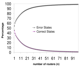
Figure 9 shows the percentage of each of the correct and error state spaces, and how this percentage changes with the number of routers. The figure is shown for the second case error definition. Similar results were obtained for the first case definition.
Appendix B Forward Search Algorithms
This appendix includes detailed procedures that implement the forward search method as described in Section IV. It also includes detailed statistics collected for the case study on PIM-DM.
B-A Exhaustive Search
The ExpandSpace procedure given below implements an exhaustive search, where is the working set of states to be expanded, is the set of visited states (i.e. already expanded), and is the state currently being explored. Initially, all the state sets are empty. The nextState function gets and removes the next state from , according to the search strategy; if depth first then is treated as a stack, or as a queue if breadth first.
Each state is expanded by applying the stimuli via the ‘forward’ procedure that implements the transition rules and returns the new stable state .
ExpandSpace(){
add to
while not empty {
= nextGState from ;
add to ;
state
stim applying to state {
= forward(,stim);
if or
add to ;
}
}
}
The initial state may be generated using the following procedure, that produces all possible combinations of initial states .
Init(,){
{
add to ;
= - 1;
if = 0
ExpandSpace();
else
Init(, );
remove last element of ;
}
}
This procedure is called with the following parameters: (a) number of routers as the initial and (b) the as the initial . It is a recursive procedure that does a tree search, depth first, with the number of levels equal to the number of routers and the branching factor equal to the number of initial state symbols . The complexity of this procedure is given by .
B-B Reduction Using Equivalence
We use the counting equivalence notion to reduce the complexity of the search in 3 ways:
-
1.
The first reduction we use is to investigate only the equivalent initial states, we call this algorithm Equiv. One procedure that produces such equivalent initial state space is the EquivInit procedure given below.
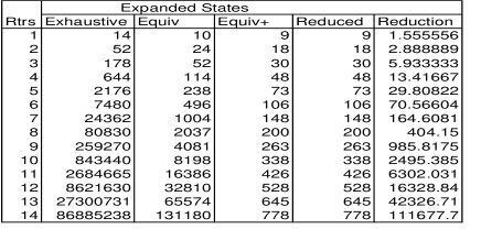
Figure 10: Simulation statistics for forward algorithms. is the number of visited states. 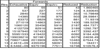
Figure 11: Simulation statistics for forward algorithms. is the number of calls to . 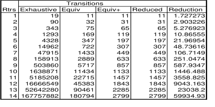
Figure 12: Simulation statistics for forward algorithms. is the number of transient states visited. 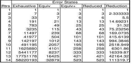
Figure 13: Simulation statistics for forward algorithms. The number of stable error states reached. EquivInit(,,){
for to {
= ;
for to
add to ;
trunc(,);
if () = 0
ExpandSpace();
else
EquivInit(,,);
}
}
This procedure is invoked with the following parameters: (a) the initial set of states as , (b) the number of routers as , and (c) the as . The procedure is recursive and produces the set of equivalent initial states and invokes the ExpandSpace procedure for each equivalent initial state. The ‘trunc’ function truncates such that contains only the state elements in after the element . For example, trunc() = .
-
2.
The second reduction we use is during state comparison. Instead of comparing the actual states, we compare and store equivalent states. Hence, the line ‘if or ’ would check for equivalent states. We call the algorithm after this second reduction Equiv+.
-
3.
The third reduction is made to eliminate redundant transitions. To achieve this reduction we add flag check before invoking forward, such as stateFlag. The flag is set to 1 when the stimuli for that specific state have been applied. We call the algorithm after the third reduction the reduced algorithm.
B-C Complexity analysis of forward search for PIM-DM
The number of reachable states visited, the number of transitions and the number of erroneous states found were recorded. The result is given in Figures 10, 11, 12, 13. The reduction is the ratio of the numbers obtained using the exhaustive algorithm to those obtained using the reduced algorithm.
The number of expanded states denotes the number of visited stable states and is measured simply as the number of states in the set in ‘ExpandSpace’ procedure. The number of forwards is the number of times the ‘forward’ procedure was called denoting the number of transitions between stable states. The number of transitions is the number of visited transient states that are increased with every new state visited in the ‘forward’ procedure. The number of error states is the number of stable (or expanded) states violating the correctness conditions.
The number of transitions is reduced from for the exhaustive algorithm to for the reduced algorithm. This means that we have obtained exponential reduction in complexity, as shown in Figure 14.
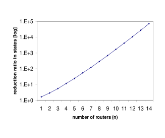
Appendix C FOTG Algorithms
This appendix includes pseudo-code for procedures implementing the fault-oriented test generation (FOTG) method presented in Section V. In addition, it includes detailed results of our case study to apply FOTG to PIM-DM.
C-A Pre-Conditions
The procedure described below takes as input the set of post-conditions for the FSM stimuli and genrates the set of pre-conditions. The ‘’ array contains the post-conditions (i.e., the effects of the stimuli on the system) and is indexed by the stimulus. The ‘stimulus’ function returns the stimulus (if any) of the condition. The ‘transition’ function returns the transition or state of the condition 303030If there’s a state in the condition, this may be viewed as transition, i.e., transition to the same state.. The pre-conditions are stored in an array ‘’ indexed by the stimulus.
PreConditions{
{
= stimulus();
= transition();
add to ;
}
}
C-B Dependency Table
The ‘dependencyTable’ procedure generates the dependency table from the transition table of conditions .
dependencyTable{
{
= end();
= start();
add to ;
}
}
For each state , that is of a transition, a set of – pairs leading to the creation of is stored in the array. For a symbol denoting initial state is added to the array entry. For our case study .
C-C Topology Synthesis
The following procedure synthesizes minimum topologies necessary to trigger the various stimuli of the protocol. It performs the third and forth steps of the topology synthesis procedure explained in Section V-B.
buildMinTopos(){
{
= end();
= stimulus();
if type() =
add to ;
else {
if
buildMinTopos();
add to ;
}
}
}
C-D Backward Search
The ‘Backward’ procedure calls the ‘Rewind’ procedure to perform the backward search. A set of visited states is kept to avoid looping. For each state in possible backward implications are attempted to obtain valid backward steps toward initial state. ‘Backward’ is called recursively for preceding states as a depth first search. If all backward branches are exhausted and no initial state was reached the state is declared unreachable.
Backward(){
if
return
add to
{
= ;
{
= Rewind(,,);
if = done
break;
else
Backward();
}
}
if all states are done
return reached
else
return unreachable
}
The ‘Rewind’ procedure takes the global state one step backward by applying the reverse transition rules. ‘replace(,,)’ replaces in with and returns the new global state. Depending on the stimulus type of the backward rule , different states in are rolled back. For and only the originator and destination of the stimulus is rolled back, respectively. For , all affected states are rolled back except the originator. is similar to except that all downstream routers or states are rolled back, while only one upstream router (the destination) is rolled back.
Rewind(,,){
if
return done;
= stimulus();
= start();
if type() = {
= replace(,,);
return ;
}
&
while not found {
= start();
if
found
}
if not found
return backTrack;
if type() = {
= replace(,,);
if checkMinTopo(,)
return ;
else
return backTrack;
if not checkConsistency(,)
return backTrack;
= ;
if type() =
if end() & not
= replace(end,start,GState);
if type() =
if end() & not
= replace(end,start,GState);
else if &
= replace(end,start,GState) once;
if checkMinTopo(,)
return ;
else
return backTrack;
}
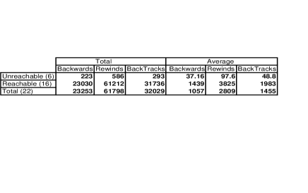
The following procedure checks for consistency of applying to .
checkConsistency(,){
& has transition
if start()
return False;
else
return True;
}
The following procedure checks if contains the necessary components to trigger the stimulus.
checkMinTopo(,){
if
return True;
else
return False;
}
C-E Simulation results
We have conducted a case study of PIM-DM analysis using FOTG. A total of 22 topologies were automatically constructed using as faults the selective loss of Join/Prune, Graft, and Assert messages. Out of the constructed topologies (or global states) 6 were unreachable global states and 16 were reachable. The statistics for the total and average number of backward calls, rewind calls and backtracks is given in Figure 15.
Although the topology synthesis study we have presented above is not complete, we have covered a large number of corner cases using only a manageable number of topologies and search steps.
To obtain a complete representation of the topologies, we suggest to use the symbolic representation 313131We have used the repetition constructs ‘0’, ‘1’, ‘*’. presented in Section III. Based on our initial estimates we expect the number of symbolic topology representations to be approximately 224 topologies, ranging from 2 to 8-router LAN topologies, for the single selective loss and single crash models.
C-F Experimental statistics for PIM-DM
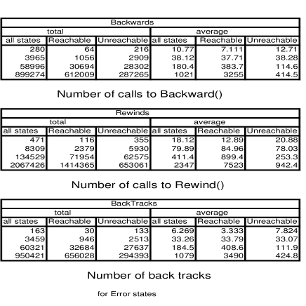
To investigate the utility of FOTG as a verification tool we ran this set of simulations. This is not, however, how FOTG is used to study protocol robustness (see previous section for case study analysis).
We also wanted to study the effect of unreachable states on the complexity of the verification. The simulations for our case study show that unreachable states do not contribute in a significant manner to the complexity of the backward search for larger topologies. Hence, in order to use FOTG as a verification tool, it is not sufficient to add the reachability detection capability to FOTG.
The backward search was applied to the equivalent error states (for LANs with 2 to 5 routers connected). The simulation setup involved a call to a procedure similar to ‘EquivInit’ in Appendix II-B, with the parameter as the set of state symbols, and after an error check was done a call is made to the ‘Backward’ procedure instead of ‘ExpandSpace’.
States were classified as reachable or unreachable. For the four topologies studied (LANs with 2 to 5 routers) statistics were measured (e.g., max, min, median, average, and total) for number of calls to the ‘Backward’ and ‘Rewind’ procedures, and the number of backTracks were measured. As shown in Figure 16, the statistics show that, as the topology grows, all the numbers for the reachable states get significantly larger than those for the unreachable states (as in Figure 17), despite the fact that that the percentage of unreachable states increases with the topology as in Figure 18. The reason for such behavior is due to the fact that when the state is unreachable the algorithm reaches a dead-end relatively early (by exhausting one branch of the search tree). However, for reachable states, the algorithm keeps on searching until it reaches an initial global state. Hence the reachable states search constitutes the major component that contributes to the complexity of the algorithm.
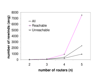
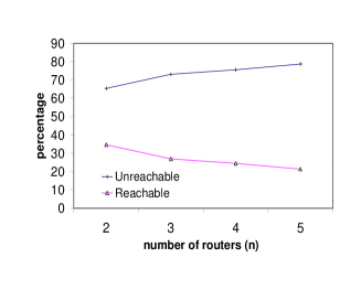
C-G Results
We have implemented an early version of the algorithm in the NS/VINT environment (see http://catarina.usc.edu/vint) and used it to drive detailed simulations of PIM-DM therein, to verify our findings. In this section we discuss the results of applying our method to PIM-DM. The analysis is conducted for single selective message loss.
For the following analyzed messages, we present the steps for topology synthesis, forward and backward implication.
C-G1 Join
Following are the resulting steps for loss:
| Synthesizing the Global State |
|---|
| 1. Set the inspected message to |
| 2. The of the post-condition is |
| 3. The state of the pre-condition is |
| 4. The stimulus of the pre-condition is . Set the inspected message to |
| 5. The of the post-condition is which can be implied from in |
| 6. The state of the pre-condition is |
| 7. The stimulus of the pre-condition is . Set the inspected message to |
| 8. The of the post-condition is which can be implied from in |
| 9. The state of the pre-condition is , an external event |
| Forward implication |
| without loss: correct state |
| loss w.r.t. : error state |
| Backward implication |
Losing the by the forwarding router leads to an error state where router is expecting packets from the LAN, but the LAN has no forwarder.
C-G2 Assert
Following are the resulting steps for the loss:
| Synthesizing the Global State |
| 1. Set the inspected message to |
| 2. The of the post-condition is |
| 3. The state of the pre-condition is |
| 4. Stimulus of pre-condition is . Set inspected message to |
| 5. The of the post-condition is , implied from in |
| 6. The state of the pre-condition is , already in |
| 7. Stimulus of pre-condition is . Set inspected message to |
| 8. The of the post-condition is , implied from in |
| 9. The stimulus of the pre-condition is , an external event |
| Forward Implication |
| error |
| Backward Implication |
The error in the case occurs even in the absence of message loss. This error occurs due to the absence of a prune to stop the flow of packets to a LAN with no downstream receivers. This problem occurs for topologies with , as that shown in Figure 19.

C-G3 Graft
Following are the resulting steps for the loss:
| Synthesizing the Global State |
|---|
| 1. Set the inspected message to |
| 2. The of the post-condition is |
| 3. the of the pre-condition is |
| 4. The stimulus of the pre-condition is |
| 5. The of the post-condition is , implied from in |
| 6. the of the pre-condition is which may be implied |
| 7. the stimulus of the pre-condition is , which is (external) |
| Forward Implication |
| without loss: |
| correct state |
| with loss of : |
| correct state |
We did not reach an error state when the was lost, with non-interleaving external events.
C-H Interleaving events and Sequencing
A message is acknowledged by the () message, and if not acknowledged it is retransmitted when the retransmission timer expires. In an attempt to create an erroneous scenario, the algorithm generates sequences to clear the retransmission timer, and insert an adverse event. Since the reception causes an upstream router to become a forwarder for the LAN, the algorithm interleaves a event as an adversary event to cause that upstream router to become a non-forwarder.
To clear the retransmission timer, the algorithm inserts the transition () in the event sequence.
Forward Implication
error state.
Backward Implication:
Using backward implication, we can construct a sequence of events leading to conditions sufficient to trigger the . From the transition table these conditions are 323232We do not show all branching or backtracking steps for simplicity.: .
To generate the we continue the backward implication and attempt to reach an initial state:
Hence, when a followed by a is interleaved with the loss, the retransmission timer is reset with the receipt of the for the first , and the systems ends up in an error state.
References
- [1] V. Paxon. End-to-End Routing Behavior in the Internet. IEEE/ACM Transactions on Networking, Vol. 5, No. 5. An earlier version appeared in Proc. ACM SIGCOMM ’96, Stanford, CA, pages 601–615, October 1997.
- [2] V. Paxon. End-to-End Internet Packet Dynamics. ACM SIGCOMM ’97, September 1997.
- [3] E. Clarke and J. Wing. Formal Methods: State of the Art and Future Directions. ACM Workshop on Strategic Directions in Computing Research, Vol. 28, No. 4, pages 626–643, December 1996.
- [4] A. Helmy. A Survey on Kernel Specification and Verification. Technical Report 97-654 of the Computer Science Department, University of Southern California. URL http://www.usc.edu/dept/cs/technical_reports.html.
- [5] D. Waitzman S. Deering, C. Partridge. Distance Vector Multicast Routing Protocol, November 1988. RFC1075.
- [6] J. Moy. Multicast Extension to OSPF. Internet Draft, September 1992.
- [7] D. Estrin, D. Farinacci, A. Helmy, V. Jacobson, and L. Wei. Protocol Independent Multicast - Dense Mode (PIM-DM): Protocol Specification. Proposed Experimental RFC. URL http://netweb.usc.edu/pim/pimdm/PIM-DM.{txt,ps}.gz, September 1996.
- [8] A. J. Ballardie, P. F. Francis, and J. Crowcroft. Core Based Trees. In Proceedings of the ACM SIGCOMM, San Francisco, 1993.
- [9] D. Estrin, D. Farinacci, A. Helmy, D. Thaler, S. Deering, M. Handley, V. Jacobson, C. Liu, P. Sharma, and L. Wei. Protocol Independent Multicast - Sparse Mode (PIM-SM): Motivation and Architecture. Proposed Experimental RFC. URL http://netweb.usc.edu/pim/pimsm/PIM-Arch.{txt,ps}.gz, October 1996.
- [10] A. Helmy, S. Gupta, D. Estrin, A. Cerpa, and Y. Yu. Performance Evaluation of Multipoint Protocols Using Systematic Scenario Synthesis: A Case Study for Timer-suppression Mechanisms. USC-CS-TR-00-726, March 2000.
- [11] F. Lin, P. Chu, and M. Liu. Protocol Verification using Reachability Analysis. Computer Communication Review, Vol. 17, No. 5, 1987.
- [12] T. Cormen, C. Leiserson, and R. Rivest. Introduction to Algorithms. The MIT Press. McGraw-Hill., 1990.
- [13] F. Pong and M. Dubois. Verification Techniques for Cache Coherence Protocols. ACM Computing Surveys, Volume 29, No. 1, pages 82–126, March 1996.
- [14] G. Holzmann. Design and Validation of Computer Protocols. AT&T Bell Labs., Prentice Hall, 1991.
- [15] D. Estrin, D. Farinacci, A. Helmy, D. Thaler, S. Deering, M. Handley, V. Jacobson, C. Liu, P. Sharma, and L. Wei. Protocol Independent Multicast - Sparse Mode (PIM-SM): Protocol Specification. RFC 2117. URL http://netweb.usc.edu/pim/pimsm/PIM-SMv2-Exp-RFC.{txt,ps}.gz, March 1997.
- [16] K. Saleh, I. Ahmed, K. Al-Saqabi, and A. Agarwal. A recovery approach to the design of stabilizing communication protocols. Journal of Computer Communication, Vol. 18, No. 4, pages 276–287, April 1995.
- [17] J. Spivey. Understanding Z: a Specification Language and its Formal Semantics. Cambridge University Press, 1988.
- [18] C. Jones. Systematic Software Development using VDM. Prentice-Hall Int’l, 1990.
- [19] R. Boyer and J. Moore. A Computational Logic Handbook. Academic Press, Boston, 1988.
- [20] S. Owre, J. Rushby, N. Shanker, and F. Henke. Formal verification for fault-tolerant architectures: Prolegomena to the design of PVS. IEEE Transactions on Software Engineering, pages 107–125, February 1995.
- [21] F. Lin, P. Chu, and M. Liu. Protocol Verification using Reachability Analysis: the state explosion problem and relief strategies. Proceedings of the ACM SIGCOMM’87, 1987.
- [22] D. Probst. Using partial-order semantics to avoid the state explosion problem in asynchronous systems. Proc. 2nd Workshop on Computer-Aided Verification, Springer Verlag, New York, 1990.
- [23] P. Godefroid. Using partial orders to improve automatic verification methods. Proc. 2nd Workshop on Computer-Aided Verification, Springer Verlag, New York, 1990.
- [24] N. Maxemchuck and K. Sabnani. Probabilistic verification of communication protocols. Proc. 7th IFIP WG 6.1 Int. Workshop on Protocol Specification, Testing, and Verification, North-Holland Publ., Amsterdam, 1987.
- [25] C. West. Protocol Validation by Random State Exploration. Proc. 6th IFIP WG 6.1 Int. Workshop on Protocol Specification, Testing, and Verification, North-Holland Publ., Amsterdam, 1986.
- [26] J. Pageot and C. Jard. Experience in guiding simulation. Proc. VIII-th Workshop on Protocol Specification, Testing, and Verification, Atlantic City, 1988, North-Holland Publ., Amsterdam, 1988.
- [27] Nancy Lynch. Distributed Algorithms. Morgan Kaufmann, 1997.
- [28] Leslie Lamport, Robert Shostak, and Marshall Pease. The Byzantine generals problem. ACM Transactions on Programming Languages and Systems, 1982.
- [29] Stephen Garland and John Guttag. A guide to LP, the Larch Prover. Research Report 82, Digital Systems Research Center, 1991.
- [30] Michael Merritt, Francesmary Modugno, and Mark Tuttle. Time constrained automata. 2nd International Conference on Concurrency Theory, 1991.
- [31] W.D. Tajibnapis. A correctness proof of a topology information maintainence protocol for a distributed computer network. Communications of the ACM, 20(7), 1977.
- [32] K. Shin and M. Chen. Performance analysis of distributed routing strategies free of ping-pong-type looping. IEEE Transactions on Computers, C-36(2):129–137, February 1987.
- [33] J. Jaffee and F. Moss. A responsive distributed routing algorithm for computer networks. July 1982.
- [34] J.J. Garcia-Luna-Aceves. Loop-free routing using diffusing computations. 1(1):130–141, February 1993.
- [35] P.M. Merlin and A. Segall. A failsafe distributed routing protocol. COM-27(9):1280–1287, 1979.
- [36] G-C. Roman, P.J. McCann, and J.Y. Plun. Assertional reasoning about pairwise transient interactions in mobile computing. In IEEE, editor, 18th International Conference on Software Engineering, pages 155–164, March 1996.
- [37] K.M. Chandy and J. Misra. Parallel Program Design. Addison-Wesley Publishing Company, Inc., 1988.
- [38] B. Hailpern. A simple protocol whose proof isn’t. COM-33(4):330–337, April 1985.
- [39] R. Milner. A Calculus of Communicating Systems. Number 92. Springer Verlag, 1980.
- [40] J. Parrow. Verifying a CSMA/CD-protocol with CCS. In VIII, pages 373–384. IFIP, 1984.
- [41] M. Smith. Formal Verification of Communication Protocols. FORTE/PSTV’96 Conference, October 1996.
- [42] Leslie Lamport. The temporal logic of actions. ACM Transactions on Programming Languages and Systems, May 1994.
- [43] V. Klee. Combinatorial optimization: what is the state of the art? Math. Operations Research, Vol 5, 1980.
- [44] M. Yannakakis and D. Lee. Testing finite state machines. ACM Symposium on Theory of Computing (STOC), 1991.
- [45] M. Yannakakis and D. Lee. Testing Finite State Machines. Journal of computer and systems sciences, JCSS, 50(2), 1995.
- [46] M. Abramovici, M. Breuer, and A. Friedman. Digital Systems Testing and Testable Design. AT & T Labs., 1990.
- [47] B. Konemann, B. Bennetts, N. Jarwala, and B. Nadeau-Dostie. Built-In Self-Test: Assuring System Integrity. IEEE Computer Magazine, pages 39–45, November 1996.